Installation Instructions - Ove Drop-In BubbleMassage Bath - Kohler
Installation Instructions - Ove Drop-In BubbleMassage Bath - Kohler
Installation Instructions - Ove Drop-In BubbleMassage Bath - Kohler
- No tags were found...

You also want an ePaper? Increase the reach of your titles
YUMPU automatically turns print PDFs into web optimized ePapers that Google loves.
BUBBLE MASSAGE BATHINSTALLATION INSTRUCTIONSBEFORE YOU BEGIN• Please read these instructions carefully to familiariseyourself with the required tools, materials, andinstallation sequences. Follow the sections thatpertain to your particular installation. This will helpyou avoid costly mistakes. <strong>In</strong> addition to properinstallation, read all operating and safety instructions.• All information is based on the latest productinformation available at the time of publication.<strong>Kohler</strong> NZ Ltd. reserves the right to make changes inproduct characteristics, packaging, or availability atany time without notice.• These instructions contain important care, cleaning,and warranty information-ROUGHING-IN & DIMENSIONSA. BUBBLE MASSAGE BATHOrdering <strong>In</strong>formationProductAir switchREGATTA drop in 11303A-GAB-0EVOK RECT drop in 18263A-GAB-0EVOK RECT freestanding 18344A-GAB-0EVOK OVAL drop in 18346A-GAB-0EVOK OVAL freestanding 18348A-GAB-0OVE RECT drop in 1709A-GAB-0ESCALE drop-<strong>In</strong>11343A-GAB-0ESCALE free Standing 11344A-GAB-0B. Required Electrical ServiceDedicated branch circuit required, protected with ClassA Ground-Fault Circuit-<strong>In</strong>terrupt (GFCI):Blower 220~240V, 10.A, 50HzBlower Part # Motor Heater Voltage Freq Amperage<strong>Kohler</strong> AP300 - air switch 1128A-CP 300 W 180W 220~240 V 50-60Hz 2.2AIf supply cord or interconnection cord is damaged, it must be replaced by the manufacturer, its service agent orsimilarly qualified persons in order to avoid a hazard.C. <strong><strong>In</strong>stallation</strong>Read the entire installation instructions before beginningthe installation.D. DimensionsDetached blowers are supplied with a 1.5m flexible coupling. This allows the blower to be positioned at the installersdiscretion. For serviceability of the blower, an access panel of 450mm x 400mm must be fitted. If access to theblower is not provided, then no warranty service will be provided.11128227-A01-D Date: 10/8/2010
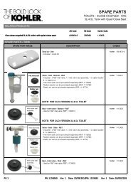
REGATTA BUBBLE MASSAGE11303A-GAB-0OVE BUBBLE MASSAGE1709A-GAB-0501128227-A01-D Date: 10/8/20102
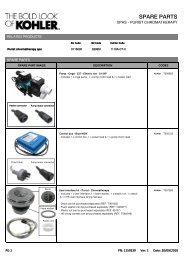
EVOK BUBBLE MASSAGE18263A-GAB-0EVOK RECT FREESTANDING BUBBLE MASSAGE18344A-GAB-071408.550762837.5167536505136101128227-A01-D Date: 10/8/2010 +3
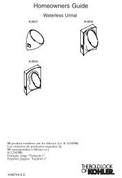
EVOK OVAL BUBBLE MASSAGE18346A-GAB-039850750850170050530EVOK OVAL FREESTANDING BUBBLE MASSAGE18348A-GAB-039850750850170039505106101128227-A01-D Date: 10/8/20104
ESCALE DROP-IN BUBBLE MASSAGE BATH11343A-GAB-0ESCALE FREESTANDING BUBBLE MASSAGE BATH11344A-GAB-0 1128227-A01-D Date: 10/8/20105
PRODUCT NOTICESA. <strong><strong>In</strong>stallation</strong> Hazard NotificationWARNING: Risk of electrical shock. A licensedelectrician should make all electrical connections.WARNING: Risk of electrical shock. Connectonly to a circuit protected by a Ground-FaultCircuit-<strong>In</strong>terrupter (GFCI) or Earth-LeakageCircuit-Breaker (ELCB).WARNING: Risk of electrical shock. DisconnectWARNING: Keep the area around the blowermotor clean and free of debris.Ensure that thearea around the blower motor is free of sawdust,insulation, dirt, or other small loose debris. Suchmaterial could clog the blower motor air ducts andPRODUCT REQUIREMENTSA. Summary Of Key Requirements• Observe all local plumbing codes.•• Provide properly-dimensioned framing.• <strong>Bath</strong>s with airjets are designed for a variety ofinstallations, depending upon the model chosen.C. Electrical RequirementsThe installation must have a Class A Ground-FaultCircuit-<strong>In</strong>terrupter (GFCI). The GFCI protects againstLine-to-ground shock hazard. Use a 220-240 V, 10A(minimum), 50 Hz dedicated service for the bath withairjets.cause unsafe operation or affect performanceof the bath with airjets. Do not relocate thesystem in the absence of kit instructions, as thiscould adversely affect the performance and safeoperation of the bath with airjets. <strong>Kohler</strong> NZ shallnot be liable under its warranty or otherwise forpersonal injury or damage caused by any suchWARNING: Risk of injury or property damage.Please read all instructions thoroughly beforebeginning installation, including the followingProduct Requirements.B. Plumbing Specificationsbetween the valves and spout may be required.that may inadvertently be used as a means of supportare not appropriate or safe for this installation.D. Product <strong>In</strong>spectionCarefully unpack and inspect the bath with airjetsfor damage. Leave all materials in the carton duringconstruction to prevent damage.INSTALLATION REQUIREMENTSA. Tools Required• Adjustable pipe wrench• Rule• Level• Safety shoes• Safety glasses• Square• Screwdriver• Pliers• Utility knife• Pencil• Measuring TapeB. Materials Required• Plumber’s putty• Wall coverings, asnecessary• Silicone sealant• Gypsum cement(optional)• Construction adhesive(optional)• Protective covering forbathtub• Nails• Silicone Sealant• PVC CementPlus:• Conventional woodworking tools and materials orconventional bricklaying tools and materials• <strong>Drop</strong> Cloth• Construction adhesive (optional)• Cement or mortar (optional)• 2x4s or 2x6s6 1128227-A01-D Date: 10/8/2010
SITE REQUIREMENTSA. Prepare the SiteCAUTION: Risk of product damage. Do notonly support the bath by the rim.NOTICE:under the bath must provide for a minimum of 80 lbs./square foot (390kg./square metre) loading.NOTICE: Provide adequate ventilation and a minimumof 15 cubic feet (.4 cubic metres) in the installedair for the blower. Do not install the blower motor closerthan 2.5mm from the wall or other objects.•TileBrickortimber<strong>Bath</strong>Approved Tile Backing<strong>Bath</strong> rim must be fully supported.<strong>Bath</strong> may be installed next to thewall or as an island installation.<strong>In</strong>stall an access panel to allowthe pump to be serviced.• This bath may be installed in a drop-in or in an islandinstallation. An island installation requires a four-sidesurround.• <strong>In</strong>stall an access panel to allow the blower to beserviced. Ventilation access is recommended.• Construct brick, concrete or timber supports.• Ensure the bath rim is fully supported. Frame theaccordance with the roughing-in information packedwith the bath.TileApproved Tile BackingBrickortimberTypicalaccesspanelB. Whirlpool Area ConstructionPreparation (Optional)Make sure you allow for access to the blower in theevent the unit requires service. When constructing thematerial (e.g. mortar mix and ceramic or marble tiling).When choosing a blower installation position, checkthat the switch cable will reach the blower.<strong>Bath</strong> Rim<strong>Drop</strong> <strong>In</strong> <strong><strong>In</strong>stallation</strong>: Refer to rough-in notes on page 2for cut-out details. Whirlpool must be supported bothon the rim and on the supporting feet. Do not allow thewhirlpool to be supported by the rim alone.BEFORE INSTALLINGA. Your new whirlpool has been manufactured to thehighest possible standards, it has been factory testedand approved.B. When removing bath from protective carton DONOT LIFT BATH BY PIPE WORK. <strong>In</strong>spect for anypossible damage that may have occurred in transit.Position a clean drop cloth or similar material in thescratch the surface of the bath.7 1128227-A01-D Date: 10/8/2010
C. Identify suitable blower installation and access positionsbefore proceeding with installation. A suitable poweroutlet will also be required within 610mm of the blower.See section H.NOTE: NO MOTOR ACCESS NO WARRANTYSERVICE. Ventilation must be provided in order toallow heat from motor to dissipate..Blower Access*Blower Access*Blower Access*D. IMPORTANT: <strong>Bath</strong> must be installed level on all topedges.E. <strong>In</strong>stall the drain to the bath according to the drain manufacturer’s instructions. Do not connect the trap at this time.If a pop up waste/overflow has been selected as an accessory, then an extra overflow hole might require drilling.The position of the overflow holes are shown on page 2. (Refer to part ‘M’ in the next section for cutting and drillinginstructions)INSTALL THE BATHCAUTION: Risk of product damage. Do not liftthe bath with airjets by the air channels or blowermotors, or use the air channels or blower motorfor structural support of the bath.CAUTION: Risk of product damage. Do notsupport the bath by the rim.as necessary.A. Option Using a Cement or Mortar BedNOTE: Do not use gypsum cement or drywallcompound for this application, as they will not providean acceptable, durable bond.• Spread a 50mm thick layer of cement or mortar onsecure, level, and support the unit. Clear all thematerial away from the support block locations.• Position a piece of plastic drop cloth material on topof the cement or mortar bed.• With help, carefully lift the bath into place, andmake sure the support blocks do not rest in the bedMaterial.• <strong>In</strong>sert the drain tailpiece into the trap. Make sure thebath is level and resting on all support blocks.• Remove the protective tape from the rim.Clear spacesfor support blocks.Spread a 50mm Layerof Cement or MortarBed Material.1128227-A01-D Date: 10/8/20108
B. Option Using Construction Adhesive• Apply a generous amount of high-quality constructionadhesive to the bottom of the support blocks.• With help, carefully lift the bath into position.• <strong>In</strong>sert the drain tailpiece into the trap. Make sure thebath is level and resting on all support blocks.• Remove the protective tape from the rim.Apply Constructionadhesive to theSupport Blocks.C. Option Using Silicone Sealant<strong>Bath</strong> Rim• With help, carefully lift the bath into position.• <strong>In</strong>sert the drain tailpiece into the trap. Make sure thebath is level and resting on all support blocks.• Remove the protective tape from the rim. Apply acontinuous bead of high-quality silicone sealantaround the entire rim of the bath.• Allow the sealant to cure according to themanufacturer’s instructions.D. <strong>In</strong>stall the pillow rail(Regatta Bubble Massage <strong>Bath</strong> Only )• Refer to the exploded view for installationof the pillow rail.E. <strong>In</strong>stall the Blower Switch (For Detached Blower Versions Only )• Apply silicone sealant to switch and press into hole.Apply Silicon Here• Connect the air tube to the switch and to the blower.<strong>Bath</strong> Flange• Remove any excess silicone with a rag.Air SwitchTo the blower9 1128227-A01-D Date: 10/8/2010
F. <strong>In</strong>stall the Blower(For Detached Blower Versions Only )The detached blower can be installed up to 1.5m fromthe bath if desired.• Connect the flexible coupling to the blowerusing PVC cementApply PVC Cement Here• Once connected find a suitable installation position forthe blower.• Secure the blower firmly using appropriate fixings sothat the blower can not vibrate free when in useAppropriate fixingsthrough holes in blowerG. <strong>In</strong>stall the PlumbingCAUTION: Risk of property damage. Ensure awatertight seal on the bath drain.• Connect the drain to the trap according to themanufacturer’s instructions.NOTICE: An access panel will simplify future maintenance.• <strong>In</strong>stall the faucet valving according to the faucetmanufacturer’s instructions. Do not install the faucettrim until instructed. Open the hot and cold watersupplies, and check the supply connections forleakage.• Run water into the bath, and check the drainconnections for leakage.H. Make Electrical ConnectionsWARNING: Risk of electric shock. To reduce therisk of electrical shock, connect the blower motorto a properly grounded, grounding-type receptacleprotected by Ground-Fault Circuit-<strong>In</strong>terrupters(GFCIs). Do not remove the plug grounding pins.Do not use grounding adapters.NOTE: The model number and electrical rating of the bloweris printed on the blower.• The blower is equipped with a cord and plug. A licensedelectrician must install a dedicated GFCI-protected, 220V, 10A,grounded outlet. Locate the outlet behind the bath, and within610mm of the blower motor.• Plug the blower motor into this outlet.• Clean the area of all dust and debris.• Air blower must be located or fixed so that it cannotfall into the bath of spa.GFCI-Protected ReceptacleBlower MotorI. Test Run the <strong>Bath</strong> with Airjets• For information on unit operation, refer to the• Return the plastic drop cloth or other protectivesheetingto the bath. Check the drain connections for leakage.• Check all electrical connections, and make sure the • Stop the bath and drain the water.electrical power to the bath with airjets is on.• Make sure all piping connections in the air harness are secure.• Verify that the blower motor is secure.• Temporarily remove the plastic drop cloth or otherprotective sheeting from the bath.• Fill the bath to a level at least 50mm above the top ofthe highest airjet.• Check the drain piping for leaks. Repair any leaks.•airjets. Check the air piping for air leaks.1128227-A01-D Date: 10/8/201010
J. Wall Section <strong><strong>In</strong>stallation</strong> DetailREBATED INTO WALLPACKED OUT FROM WALLK. Front & Return Section <strong><strong>In</strong>stallation</strong>Ensure that the bath rim is fully supported.Build the bath support frame as shown.When the bath is securely positioned, before the unitis fully built in, install tapware, connect plumbing to Run water into the bath and check connections forleaks.Pour water around the rail support legs and check forany leaks.with installation.Please remember to provide unrestricted access to thepump to assist with future maintenance. Access panelsshould be wide enough to allow access to the motor, airblower and adjacent plumbing, and should be securedby screws to prevent unauthorised tampering.IMPORTANT:No motor access, no warranty service. L. <strong>Drop</strong>-<strong>In</strong> <strong><strong>In</strong>stallation</strong>:Spa box ledge upstandSilicone sealantFinished deck (eg. tiles)protrusions.Build stud framing as shown in diagrams, ensuring thatthe top is level. Whirlpool must be installed level at alltop edges.Ensure that the stud framing is not interfering withpump, air blower and whirlpool plumbing.Whirlpool must be supported both on the rim and onthe supporting feet. Do not allow the whirlpool to besupported by the rim alone.Please remember to provide unrestricted access to thepump to assist with future maintenance. Access panelsshould be wide enough to allow access to the motor, airblower and adjacent plumbing, and should be securedby screws to prevent unauthorised tampering.IMPORTANT:No motor access, no warranty service.Min 80 mmWaterproof membraneWater resistant wall materialTimber framing or brick wallFinished deck (eg. tiles)Water resistant wall materialSilicone sealantTimber framing or brick wallWaterproof membraneSpa box ledge upstand11 1128227-A01-D Date: 10/8/2010
M. Drilling And Cutting AcrylicDRILLING: Small holes can be drilled with a twist drill,but the cutting edge MUST be backed off with an oilstone (the sharp edge dulled). Large holes must bedrilled with a hole saw. Maximum drill size-12mm. Drillspeeds-6mmx1800 RPM-12mmx900 RPM.NOTE: Always drill from acrylic surface.CUTTING: If for any reason the acrylic requires cutting,should happen to be damaged, it can be restored bypolishing with an abrasive cleaner. Deep scratchescan be removed by rubbing with 600 grade wet & drysandpaper then polishing.N. Clean-Up After <strong><strong>In</strong>stallation</strong>• Clean the area around the blower motor of all dustand debris.• Use warm water and a liquid detergent to clean thesurface of the bath with airjets. Do not use abrasivecleaners, as they may scratch and dull the surface.Do not use powdered cleaners unless the cleaneris fully dissolved in water. Solid substancescould block the airjets. Do not use bleach orammonia cleaning solutions. Chemically activecleaning solutions can damage the bath surface.Refer to the homeowners guide for normal cleaningrecommendations.BATH OPERATIONA. Fill the <strong>Bath</strong>CAUTION: Risk of product damage. Ensurethat the area around the blower motor is freeof sawdust, insulation, dirt, or other small loosedebris. Such material could clog the blowerNOTE: Please read these steps carefully beforeyou operate your bath with airjets. Troubleshoot anyproblems using the “Troubleshooting” section.blower motor.B. Control Switch OperationPush 1 = blower onPush 2 = blower offC. Preliminary Checks• Temporarily remove all access panels.• Verify that the union connection at the check valve issecurely hand tightened.• Verify that the blower motor is securely installed.• Verify that the swtich tube is securely connected atthe air switch and at the blower motor.• Fill the bath to a level at least 50mm above the top ofthe highest airjet.1128227-A01-D Date: 10/8/201012
D. Confirm Air System Operation• Press the air switch once.• Observe that the blower motor starts• Observe that air is blowing through all of the airjets.• Press the air switch again to stop the blower motor.E. Regular Care and MaintenanceTROUBLESHOOTING CHARTSYMPTOMS PROBABLE CAUSES CORRECTIVE ACTION1. <strong>Bath</strong> with airjets does notstart.A. No power to blower motor. A. Set/reset GFCI or ELCB breaker;check wiring.B. Air switch tube may have water in it. B. Remove air switch tube and drain,C. Air switch is faulty or disconnected. C. Check air tube connections.2. Blower motor starts, butthere are few or no bubbles.D. Blower motor does not work. D. Replace blower motor.A. Blower motor is disconnected. A. Connect blower motor to air harness.B. Clean the area around the blowermotor. Ensure adequate ventilation.3. <strong>Bath</strong> stops automatically A. GFCI or ELCB trips. A. Identify source of fault and correct.B. Motor overheated and protectiondevice activated.B. Check for blockage at motor vents.Remove blockage and allow motor tocool.13 1128227-A01-D Date: 10/8/2010
SERVICABLE PARTSPop up waste and overflowT1510101034122-FJCheck Valve112254280mm Leveling Kit SetAir switch and blower 1128A-CPFlexible connection tube1022891CONTACT AND WARRANTY INFORMATIONFor warranty information, please visit our websiteAustraliawww.au.kohler.comNew Zealandwww.kohler.co.nzCALL US FOR HELP1128227-A01-D Date: 10/8/201014