RT-PLUS Modular
RT-PLUS Modular
RT-PLUS Modular
- No tags were found...

Create successful ePaper yourself
Turn your PDF publications into a flip-book with our unique Google optimized e-Paper software.
Page 4 Lit. No. 1313-e-Ed. 07/07
2. Concept / DescriptionThe <strong>RT</strong>-<strong>PLUS</strong> <strong>Modular</strong> is a constrained rotating knee prosthesis for cemented implantation.The prosthesis allows an internal/external rotation of approx. 10° each. This is locked by the tibialinsertwhen extended. Due to the peg design, the prosthesis has the capability of elongation, i.e., fordistraction between the femoral and the tibial components. In an extreme flexed position, the femoralcomponent can lift off the tibial-insert, which reduces the sagittal leverage forces that have aneffect on the prosthesis stem in this load situation.The implant allows sparing resections. The cut compatibility with the tricompartmental prosthesisTC-<strong>PLUS</strong> permits if necessary an intraoperative switchover from the resurfacing to the constrainedrotating knee.The femoral and tibial components of <strong>RT</strong>-<strong>PLUS</strong> <strong>Modular</strong> are identical to those of <strong>RT</strong>-<strong>PLUS</strong>,with the exception of the additional option to connect stems and augmentation blocks. The tibialinserts are the same. As a result, the femoral and tibial components in both these systems are entirelycross-compatible. All the stems of <strong>RT</strong>-<strong>PLUS</strong> <strong>Modular</strong> can be combined with the femoral andtibial components of <strong>RT</strong>-<strong>PLUS</strong> <strong>Modular</strong> to suit requirements.The implants are available in five sizes ( corresponding to <strong>RT</strong>-<strong>PLUS</strong> sizes 2, 4, 6, 8 and 10 ).Apart from size 2, the sizes can be combined with the next size up or down ( see product overviewfrom page 72 ).Note: <strong>RT</strong>-<strong>PLUS</strong> <strong>Modular</strong> requires condylar support for the femoral/tibial components. The forceshave to be absorbed by the condyles as well as by the stems.Page 6 Lit. No. 1313-e-Ed. 07/07
Product DescriptionFemoral ComponentThe femoral component is manufactured from CoCrMo alloyand is asymmetrical.The patellar groove is deeply hollowed out and presents ananatomical oblique outline. This feature offers improved patellartracking and leverage on the knee extensor apparatus.The joint mechanism is contained in a narrow box, the width ofwhich is comparable to that of a "posterior stabilised" implant.This allows sparing bone resection, which reduces the risk offemoral condyle fracture.The rotation peg of 40 mm length provides adequate securityagainst dislocation, but the components can nevertheless beeasily coupled. Because of the design of the condyles, physiological"rollback" is possible, which improves the flexion capabilityof the joint.The joint mechanism has been designed in such way, that allmetal components ( peg & joint axis ) interface with UHMWpolyethyleneto absorb the stress forces therefore preventingpremature wear.A modular stem connection allows the use of different stemsto stabilise the femoral component.To compensate femoral bone defects, distal and/or posteriorfemoral augmentation blocks can be fixed to the femoral component.The femoral component is available in sizes 2, 4, 6, 8 and 10.Please see the available sizes in the implant table ( on page 51 ff ).Page 7 Lit. No. 1313-e-Ed. 07/07
Patellar ComponentThe all-poly ( UHMW- polyethylene ) patellar component has asymmetrical biconcave surface for better tracking.Tibial InsertThe simple and securely anchored tibial insert, is manufacturedfrom UHMW-polyethylene and is available in three differentheights of 8 mm, 11 mm and 14 mm, in order to restorethe joint height independent to the degree of tibial bone substanceloss.The special design of the polyethylene insert enables an easycoupling of the prosthesis, for which only minimal distraction isrequired.The minimum effective PE thickness in the load zone is 8 mm.The selected manufacturing method, the design ( condyles )and the high-quality material combine to form the proven wearresistanceof the insert.The tibial inserts are identical to those in the <strong>RT</strong>-<strong>PLUS</strong> portfolio.Tibial ComponentThe symmetrical tibial component is manufactured fromCoCrMo alloy.In order to prevent polyethylene wear inside the tibial component,the base plate is polished on the inside and the insert iscompletely enclosed along its entire circumference.A modular stem connection allows the use of different stems,which serve to stabilise the tibial component.To compensate tibial bone defects, proximal tibial blocks canbe fixed on the tibial component.The tibial component is available in sizes 2, 4, 6, 8 and 10.Page 8 Lit. No. 1313-e-Ed. 07/07
Femoral and Tibial BlocksThe femoral and tibial blocks are manufactured from CoCrMoalloy.In order to compensate for different femoral and/or tibial bonedefects, there are distal femoral blocks available in heights of5 mm, 10 mm and 15 mm, posterior femoral blocks in heightsof 5 mm and 10 mm and proximal tibial blocks in heights of 5mm, 10 mm and 15 mm.The same femoral blocks are used for the medial- as for thelateral-condyle of the femoral component. The same tibialblocks, except height of 15mm, are used for the medial- as forthe lateral-condyle of the tibial component.The blocks have to be assembled to the femoral and tibialcomponents with screws and can then be cemented.Cemented StemThe femoral and tibial components can be intramedullary anchoredin the bone by cemented conical stems, made offorged CoCrMo alloy.Available in lengths; 95 mm, 120 mm and 160 mm.Non-Cemented StemsThe femoral and tibial components can also be stabilised intothe bone by using non-cemented cylindrical stems, made offorged Ti6Al4V alloy. These stems are not suitable for primaryanchorage; therefore they are not designed for osseointegration.A wide stems range enables an optimum adaptation to differentindications. They are available in various diameters( Ø 10, Ø 12, Ø 14, Ø 16, Ø 18 and Ø 20 mm) and lengths(95 mm, 120 mm, 160 mm and 200 mm ) in order to ensureoptimum anchorage, even with a variety of femoral or tibialgeometries.Please see the available sizes in the implant table ( on page 51 ff ).Page 9 Lit. No. 1313-e-Ed. 07/07
3. IndicationsThe principal preoperative planning factor is the correct diagnosis. It has to be determined whetherthe bone and stability situation require the implantation of a constrained prosthesis.The main indications for implantation of <strong>RT</strong>-<strong>PLUS</strong> <strong>Modular</strong> are :• High-grade joint destruction with considerable loss of function and requirement for additionalstabilisation with longer stems and reconstruction of bone defects• Severe joint instability that predictably cannot be corrected by suitable bone reconstruction(bone-grafts) or soft tissue intervention• Marked contractures and axial displacements of more than 15° - 20°• Failure after surface replacement ( e.g. infection, loosening ) - Revision of a primary prostheses• Trauma - induced femoral or tibial fractures• Due to the design, it is possible to switch with relatively little effort, even intra-operatively, fromthe TC-<strong>PLUS</strong> knee system to the <strong>RT</strong>-<strong>PLUS</strong> <strong>Modular</strong> knee system, since the resections andprosthesis sizes are matchingPage 10 Lit. No. 1313-e-Ed. 07/07
4. ContraindicationsContraindications are :• Acute or chronic, local or systemic infections ( or in the case of a corresponding anamnesis )• Severe muscle, nerve or vascular diseases that endangers the affected extremity• Lacking bone substance or inadequate bone quality that endangers a stable seating of theprosthesis• Severe adiposity• All concomitant diseases that may endanger the function of the implant. These include in particularextreme insufficiency of the knee extensor mechanism, which can lead to excessive jointdistortion; or severe adiposity which can lead to a dorsal impingement, which may uncouple thecomponents. In these cases it may be advisable to use a hinge or a tumour prosthesis• Patient hypersensitivities or allergies to the materials used• Strenuous physical activity ( e.g. competitive sport, hard physical work )See also instructions on the package insertPage 11 Lit. No. 1313-e-Ed. 07/07
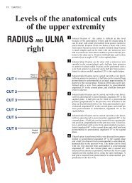
5. Case StudyPreoperative SituationPatient with severe joint instability (varus gonarthrosis) as well as medial joint destruction.Page 12 Lit. No. 1313-e-Ed. 07/07
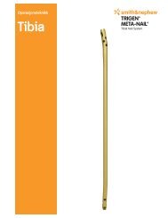
Postoperative ResultImmediately postoperative; functional, pain-free reconstruction with <strong>RT</strong>-<strong>PLUS</strong> <strong>Modular</strong> knee.Page 13 Lit. No. 1313-e-Ed. 07/07
6. Preoperative PlanningA full-leg X-ray with the patient in the standing position is recommended for preoperative planningpurposes. If this is not possible, an X-ray of the thigh, including the femoral head, should be taken.The X-ray images of the knee joint at three levels should be available for planning the surgery. Atangential patellar exposure, a frontal and a sagittal to the leg axis exposure must be taken.For preoperative planning there are X-ray templates available:with scale of 1.15:1 Lit. No. 1135 and with scale of 1:1Lit. No. 1584 ( see page 70 ). The lateral view of the condylesis decisive. If these are no longer completely intact, it is possibleto switch to the condylar width. In cases of doubt, thesmaller implant should be selected to prevent the prosthesiscomponents from protruding. In normal cases, the size determinationand the correct positioning of the prosthesis arecontrolled intraoperatively with relevant instruments andplanning may also be possible on the unrestored oppositeside leg.Note: The femoral and tibial component sizes can all becombined with the next size up or down ( see product overviewon page 72 ff ). This does not apply to combinations ofsizes 2 and 4.Large deviations of the femoral neck angle as well as severedeformities of femur and tibia ( e.g. posttraumatic axial deformities) must be taken into consideration during surgicalplanning.In cases of deformities away from the knee joint that adverselyinfluence the mechanical axis, additional correctiveosteotomies may be indicated.Page 14 Lit. No. 1313-e-Ed. 07/07
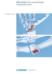
Planning of surgery using the radiographThe following procedure is recommendedfor the anterior-posterior whole leg imagingprocess:1. The femoral axis A ( anatomical axis )is drawn onto the radiograph.2. A line is drawn from the femoral headto the centre of the knee ( mechanicalaxis D ) on the radiograph.3. The angle measured between the anatomicaland the mechanical axis = angleα determines the valgus angle.( Lit No. 1112 ).4. The tibial axis B is drawn in and thetibial resection plane E is determinedto avoid excessive resection, especiallywhere there are defects.5. The component sizes and resectiondepths are determined preoperativelyusing the X-ray templates ( see page70 ) in A/P and the lateral planes.αDCA6. The mechanical leg axis C shouldmerge with lines D and B after correction.BA Anatomical femoral axisB Anatomical tibial axisC Mechanical leg axisD Mechanical femoral axisE Tibial resection depth ( mm )α Valgus anglePreop.Postop.Page 15 Lit. No. 1313-e-Ed. 07/07
αACEPage 16 Lit. No. 1313-e-Ed. 07/07
Page 17 Lit. No. 1313-e-Ed. 07/07
7. Surgical TechniquePositioning of the patient for the surgerySurgery is performed whilst the patient is supine. It is recommendedthat the blood supply be partially blocked withthe use of a tourniquet. But this is not absolutely necessary.The leg must be covered, so as to allow movementand secured to the operating table in such a way that theknee joint is brought into a stable 90° flexion position.Most of the surgical steps are performed in this position.Surgical procedureThe skin incision can be a midline incision or a parapatellarincision. If there are scars from skin incisions madeduring previous surgery, it is advisable to use them foraccess in order to reduce the risk of cutaneous bloodflowdisorders. Medial arthrotomy is recommended, or an approachadapted to the pathological situation.After the usual preparation ( meniscus resection, removalof osteophytes and synovectomy if necessary ), the cruciateligaments are sectioned and if necessary, the collateralligaments are removed close to the bone.Page 18 Lit. No. 1313-e-Ed. 07/07
Overview of the resections sequences for primary applicationIt is important that the flexion and extension gaps are identical.( evtl. )1. Distal femoral resection and optional distal augmentresection2. A/P femoral resections and optional posterior augmentresection( evtl. )3. Chamfer resections and cutting out of the boxRemove residual posterior condyles if presentNote: To avoid the risk of a condyle fracture, werecommend to prepare the box after tibial preparation4. Tibial resection and optional augment resection( evtl. )5. Patellar resection ( optional )Note: Only 1.0 mm saw blades must be used for all bone resections! ( See page 71 )Page 19 Lit. No. 1313-e-Ed. 07/07
Overview of the resections sequences for revision applicationThe bone resections are refreshed after extraction of the primary implants.1. Distal femoral resection and optional distal augmentresection( evtl. )1. A/P femoral resections and optional posterior augmentresection( evtl. )2. Chamfer resections and cutting out of the boxRemove residual posterior condyles if presentNote: To avoid the risk of a condyle fracture, werecommend to prepare the box after tibial preparation3. Tibial resection and optional augment resection( evtl. )4. Patellar resection ( optional )Note: Only 1.0 mm saw blades must be used for all bone resection! ( See page 71 )Page 20 Lit. No. 1313-e-Ed. 07/07
Page 21 Lit. No. 1313-e-Ed. 07/07
Femoral PreparationAccess: Please refer to the relevant surgical textbooks for the initial access to the knee.Note: In addition to the bone resections, it is important to correct any ligament imbalance byappropriate soft-tissue procedures. If necessary, a general release should be performed on the sideof the contracture prior to the bone resections.The leg is flexed and any osteophytes on the femur and tibia should be removed. This will providesgood exposure of the knee joint, which facilitates size determination.Femoral size determinationUse the femoral sizer («2», «4», «6», «8» or «10») to determinethe anterior and posterior size and also the medial andlateral size.Note: The line in the sagittal view of the femoral sizer showsthe position of the femoral IM canal, i.e. the position of thestem.Femur openingThe adjustable IM femoral drill guide is set to the plannedsize of the femoral components ( size marking «2», «4-6-8»or «10» ) and inserted under the quadriceps into the centreof the femur. The distal stop should be on the medialcondyle. Make sure that the gauge is flat on the anteriorfemoral cortical bone in the direction of the femoral axis.Open the femoral IM canal with the Ø 8 mm IM drill.Important: To ensure an optimal position of the femoral drillguide on the condyles, gently tap the M/L area, not the drillguide section of the instrument.Page 22 Lit. No. 1313-e-Ed. 07/07
The Ø 8 mm IM rod is carefully inserted using the modularhandle to approximately the isthmus of the femoral IM canaland removed again. It is important to work carefully to preventexcess pressure in the IM canal.The femoral IM canal is opened further with the Ø 8 / 14 mmstepped drill. Note that the drill is positioned at the entrypoint of the femoral IM canal, previously determinated by theIM drill. The drill direction is along the femoral axis. Drill asfar as the stop.Note: The femoral IM canal, which determines the implantsstem position, must be opened carefully (reference for thefemoral position) to prevent the development of a relativeextension position (risk of notching) or flexion position (projectingpatella).Preparing the femoral anchorageReamers are used carefully and in progressive stages (start-with «Ø 10») to ream to the required stem diameter andingdepth.Notes:Reamers are available in diameter «Ø 10», «Ø 12»,«Ø 14», «Ø 16», «Ø 18» and «Ø 20». The depth indicator ison the reamer: observe the laser markings («95», «120»,«160» and «200»).When using cemented stems, the Ø 12 mm reamer is usedto drill to the desired depth and the corresponding noncementedtrial stem is used. Cemented stems are availablein 95 mm, 120 mm and 160 mm lengths.The 200 mm length is only available in the non-cementedversion.Page 23 Lit. No. 1313-e-Ed. 07/07
Controlling the stem positionAn extramedullary reamer alignment guide, which is attachedto the reamer, can be used to check the position ofthe stem in axial alignment and depth ( the end of thereamer alignment guide corresponds to the tip of thereamer )Preparing the femoral stem connectionIf it is reamed only to diameters «Ø 10», «Ø 12» or«Ø 14», the stem connection recess has to be reamed withthe Ø 10 / 16 mm stepped reamer until the laser marking( corresponding to the resection level ).IM positioning and control with trial stemsThe chosen trial stem is attached to the extension for trialstem ( Ø 8 mm ) and with the modular handle carefully insertedinto the femoral IM canal so the line marked with«PRIMARY» respectively «REV.» is approximately level tothe distal bone resection. The modular handle is now removed.It is important to avoid putting excessive pressure inthe femoralIM canal.Note: With too short IM guidance, the alignment may beincorrect ( varus / valgus, extension / flexion ).Page 24 Lit. No. 1313-e-Ed. 07/07
Locating the distal femoral cutting blockThe «6°» femoral bushing corresponds to the angle α determinedin the preoperative planning. The femoral bushingis inserted into the femoral suspension device, so that de-mark «L» for leftpending on which side is the operation, theknee or «R» for right knee is visible on the arrow «».Note: Make sure that the femoral bushing is inserted in thecorrect ( «L» or «R» ) position. Adjustment and correctionoccurs with removing, rotating by 180° and re-inserting thefemoral bushing.The femoral / tibial revision cutting block is screwed to thefemoral suspension device and positioned over the trial stemextension ( Ø 8 mm ). The handles can be attached.Note: In revision cases, the 7 mm distal revision spacer forfemoral condyle is attached to the femoral suspension device( black plastic component in picture ). This substitutesthe missing distal bone substance. The resulting resectionremains still 2 mm.Align the device with regard to rotation. Note that the removablehandles are parallel to the epicondylar axis.After preliminary drilling with the Ø 3.2 mm drill, from distalthe femoral suspension device is fixed with a bone pin( 75 mm long ).After preliminary drilling with the Ø 3.2 mm drill, the femoral /tibial revision cutting block is fixed with two bone pins ( 75mm long ) through the holes marked «0». This position re-which corresponds to thesects 9 mm from the distal femur,distal thickness of the femoral prosthesis without femoralblocks.Page 25 Lit. No. 1313-e-Ed. 07/07
The bone pin on the femoral suspension device is removedwith pin extractor. After loosening the fixation screw the trialstem with extension ( Ø 8 mm ) are removed using themodular handle.The suspension device is now removed.Notes:The resection depth can be adjusted proximally and distallyin 2 mm increments ( ± 4 mm ).The side handles can be removed from the femoral suspensiondevice and attached on the femoral / tibial revision cuttingblock.Distal femoral resectionThe femoral / tibial revision cutting block is slid onto thebone. The distal femoral resection is then performed using a1 mm saw blade through the «0» saw slot ( closed slot withfacet ).When using distal femoral augmentation blocks the resectionis performed through the open saw slots. Augmentationblocks of 5 mm, 10 mm and 15 mm are available.Notes:If there is an extension deficit, it is recommended to movethe distal resection 2 - 4 mm proximally to adjust the extensiongap. For hyper-mobile patients, a 2 mm smaller distalfemoral resection is recommended.The distal resection is the reference for the following stepsand has to be checked for accuracy.The femoral / tibial revision cutting block does not haveto be removed yet because it will be used later.Controlling the femoral sizeThe femoral size is again controlled in order to determine thedefinitive size.Notes:During medial / lateral measurement, take the external widthof the sizer as reference.The side handles can be removed from the femoral / tibialrevision cutting block and attached on the femoral A/P femoralcutting blockrevision.Page 26 Lit. No. 1313-e-Ed. 07/07
Locating the A/P femoral cutting blockThe chosen trial stem is attached to the extension for trialstem ( Ø 8 mm ) and inserted into the femoral IM canal. TheA/P femoral cutting block revision is placed on top.Note: When using distal femoral augmentation blocks thecorresponding blocks must be fixed on the A/P femoral cuttingblock revision. Respect the thickness ( «5mm», «10mm»or «15mm» ) and size ( «2, 4» or «6, 8, 10» ).The rotation of the A/P femoral cutting block revision is adjustedby applying anteriorly the femoral / tibial revision cuttingblock.Note: If the rotation of the A/P femoral cutting block revisionhas to be readjusted, the rotation is set visually in relation tothe epicondylar axis with aid of the side attached handles.After preliminary drilling with the Ø 3.2 mm drill, the A/Pfemoral cutting block revision is fixed with two bone pins( 38 mm with head ) through the lateral 45° oblique holes.With the resection stylus, the anterior and posterior resectionplane and height are checked.A/P and chamfer resectionsThe anterior femoral resection is made through the closedsaw slot with the 1 mm saw blade ( anterior slot with facet).The posterior femoral resection is made through the twoopen posterior saw slots (slots with facet).When using posterior femoral augmentation blocks, the resectionis made through the open 5 mm and 10 mm sawslots.Page 27 Lit. No. 1313-e-Ed. 07/07
The femoral chamfer resections are made through the correspondingslots ( slots with facet ).Preparing the femoral box ( IM )Note: In order to improve support for the Hohman, we rec-ommend preparing the femoral box after tibial preparation.This application is performed when bone tissue is notavailable to ensure good instrument support ( especiallyin the anterior bone area and after explantation of aprosthesis ). In case of good distal and anterior bonesupport, the EM femoral box preparation is preferred( see page 30 ).The A/P femoral cutting block revision is removed and thefemoral resections can be checked.Slide the trial stem already used with the trial stem extension( Ø 8 mm ) into the femoral IM canal again using the modularhandle and now detach the modular handle.Slide the box saw guide IM positioning device ( size 2 orsizes 4 - 10 ) onto the extension up to the distal cut with thebox saw guide positioner ( observe size ). It is important forthe box saw guide to be flush with the cut surfaces.Note: When using distal femoral blocks, mount the appropriateblocks on the femoral cutting block. Observe the appropriatethickness ( «5mm», «10mm» or «15mm» ).The side handles can be attached to the box saw guide positioningdevice.Note: If required ( absent anterior bone tissue ) adjust rotationwith the aid of the side handles, reference to the femoralepicondyle.Page 28 Lit. No. 1313-e-Ed. 07/07
Fix the box saw guide IM positioning device with pins withHead ( 38 mm ) through the distal holes.Together with the trial stem and the trial stem extension,withdraw the box saw guide positioner using the trial stemhandle, which is attached to the trial stem extension.The IM box saw guide ( guide for size 2 and sizes 4 – 10 )can be slid in the positioning device.Perform the cuts with a special 13 mm wide saw blade,which is introduced up to the « <strong>RT</strong> 45 » mark.Note: Protect vessels and nerves in the popliteal fossa.Remove all the pins, the IM box saw guide anding device.the position-Excavated the femoral box with a thin, straight osteotomeand a luer along the outer limits marked and prepared withthe saw blade. ( with the osteotome, the two lateral box cutsare carefully posteriorely extend ).Cut off the upper bone edge to provide space for the roundingfrom the patellar shield to the box wall.Page 29 Lit. No. 1313-e-Ed. 07/07
Note: Helpfully a "cross" can be prepared with the saw forremoving the femoral box. The remaining triangle bone isfinally removed by using a luer.Check box position and box depth and finalize with the boxrasp ( rasps for size 2 and for sizes 4 - 10 ).Important: Introduce the box rasp only in the longitudinaldirection; do not jam or tilt it because this can cause breakageof the femoral condyle.Controlling the femoral resections and anchorageThe femoral trial is screwed with the trial stem ( correspondingto the last reamer ) and inserted with the impactor.Note: When using distal and/or posterior femoral augmenta-on the femoraltion blocks, corresponding femoral trial blocks( «5mm», «10mm» or «15mm» ) are available, which arefixed laterally trial.Removing the dorsal condyle residueImportant: This must be checked in all cases!After having completed the femoral resections, use thecurved osteotome to remove all osteophytes as well as protrudingposterior condyles. At this point, a posterior contracturecan also be released. This will improve flexion and prebonyvent possible damage to the polyethylene insert by theseprojections.Notes:The femoral trial is used as reference for resection of thebone with the curved osteotome.The femoral trial can be removed with using the slap hamforprotecting themer. If necessary, can be left in placefemoral condyle during tibial preparation.It is recommended to leave the femoral trial component assembledwith stem and eventually augmentation blocks to beused as reference, respectively as comparison componentwhen assembling the definitive implant.Page 30 Lit. No. 1313-e-Ed. 07/07
EM Femoral Box Preparation OptionIf bone tissue is distally and anteriorly available to ensure good instrument support, the "EM femoralbox processing" version can be proceeded ( this version is faster and easier in handling ).EM Preparation of the femoral boxNote: In order to improve support for the Hohman, we recommendpreparing the femoral box after tibial preparation.For this application, anterior bone substance has to beavailable!To position medio-lateral the femoral box saw guide, respectivelythe femoral component, use the centering template,which is inserted through the anterior saw slot of the A/Pfemoral revision cutting block in regards to the femoral size,to made a mark ( e.g. with an electrocauter or a pin ) on theanterior cortical bone.On the anterior cortical bone marking, the femoral box sawguide (guides for size 2 and sizes 4 - 10) is aligned and fixedwith bone pins.It is important that the box saw guide is flush with the resections.Note: When using distal femoral augmentation blocks thecorresponding blocks must be fixed on the box saw guide.Respect the thickness ( «5mm», «10mm» or «15mm» )The side handles can be attached on the box saw guide.The resections are performed using a special 13 mm widesaw blade ( see page 71 ). The saw blade is inserted up tothe «<strong>RT</strong> 45» mark.Note: Protect the vessels and nerves in the popliteal fossa.In the case of the guide for sizes 4 - 10, make the anteriorbox cut in the saw slot of the respective size.Following, the box saw guide is removed.The next cuts can be found on page 28 ff.Page 31 Lit. No. 1313-e-Ed. 07/07
Tibial PreparationThe leg is flexed and any remaining osteophytes and the intercondylar eminence are removed.Tibia openingOpen the tibial IM canal with the Ø 8 / 14 mm stepped drill.Position the hole centrally M/L and one third from anterior.⅓ ⅔Preparing the tibial anchorageReamers are used carefully and in progressive stages( starting with «Ø 10» ) to ream to the required stem diameterand depth.Notes:Reamers are available in diameter «Ø 10», «Ø 12»,«Ø 14», «Ø 16», «Ø 18» and «Ø 20». The depth indicator ison the reamer: observe the laser markings («95», «120»,«160» and «200»).When using cemented stems, the Ø 12 mm reamer is usedto drill to the desired depth and the corresponding noncementedtrial stem is used. Cemented stems are availablein 95 mm, 120 mm and 160 mm lengths.The 200 mm length is only available in the non-cementedversion.Controlling the stem positionAn extramedullary reamer alignment guide, which is attachedto the reamer, can be used to check the position ofthe stem in axial alignment and depth ( the end of thereamer alignment guide corresponds to the tip of thereamer ).Page 32 Lit. No. 1313-e-Ed. 07/07
Preparing the tibial stem connectionIf it is reamed only to diameters «Ø 10», «Ø 12» or«Ø 14», the stem connection recess has to be reamed withthe Ø 10 / 16 mm stepped reamer until the laser marking( corresponding to the resection level ).IM positioning and control with trial stemsThe chosen trial stem is attached to the extension for trialstem ( Ø 8 mm ) and with the modular handle carefully in-into the tibial IM canal so the line marked withserted«PRIMARY» respectively «REV.» is approximately level tothe proximal bone resection. The modular handle is nowremoved. It is important to avoid putting excessive pressurein the tibial IM canal.Note: With too short IM guidance, the alignment may beincorrect ( varus / valgus, extension / flexion ).Locating the tibial cutting blockThe two tibial resection guide IM components are coupledtogether by jointing arrow «» to arrow «» and pressingthe button.The femoral / tibial revision cutting block is attached to thetibial resection guide IM with the top small grub screw andslid completely onto the Ø 8 mm extension for trial stem.Note: Ensure the lock lever is set to «OPEN» to slide inplace the tibial resection guide IM. The lock lever is thenreversed to fix the tibial resection guide IM in place.OPENThe femoral / tibial revision cutting block is first lifted upwardsby pressing the button so the tibial stylus can be attached.Page 33 Lit. No. 1313-e-Ed. 07/07
Setting the resection heightThe tibial stylus is positioned on the tibial plateau. The tibialstylus can be used for both primary resections( «11 mm» marking ) and for revisions resections ( «1 mm»marking).Notes:In primary revision procedures, the «11 mm» tibial stylus ispositioned on the lowest point of the less damaged condyle.In revision procedures where no tibial augmentation blocksare required, the «1 mm» tibial stylus is positioned on thelowest area of the tibial plateau.In revision procedures where augmentation blocks are required,«1 mm» tibial stylus is positioned on the lowest pointof the less damaged condyle.Controlling the alignment and the tibial resectionThe alignment is checked again with the axial alignment rod.The rod tip must point to the centre of the ankle joint.The tibial stylus can now be removed.The resection height is checked with the resection stylus.The femoral / tibial cutting block can be adjusted using thelarge grub screw ± 6 mm.Note: The top small grub screw is used for assembling thefemoral / tibial revision cutting block only.+60-6Page 34 Lit. No. 1313-e-Ed. 07/07
After preliminary drilling with the Ø 3.2 mm drill, the femoral /tibial revision cutting block is fixed with two bone pins( 75 mm or 100 mm long ) through the holes marked «0».Handles can be attached.The lock lever is set to «OPEN» and the tibial resectionguide IM is removed from the femoral / tibial revision cuttingblock by unscrewing the top small grub screw. The trial stemwith the extension are also removed using the modular handle.The femoral / tibial revision cutting block is slid onto thebone.Tibial resectionThe tibial resection is performed using a 1 mm saw bladethrough the «0» saw slot ( closed slot with facet ).Note: The ligaments must be protected during all resections.When using tibial blocks the resection is conducted throughthe open saw slots. Blocks 5 mm, 10 mm and 15 mm highare available.Page 35 Lit. No. 1313-e-Ed. 07/07
As guidance for the vertical tibial augmentation block cut,two bone pins (length 75 mm or 100 mm) are inserted intothe two proximal holes level with closed saw slot. The verticalcut is performed between the two pins to the depth of theaugmentation block.Note: If the femoral / tibial revision cutting block is distally orproximally relocated ( purpose of thicker or thinner bone resection), this is moved to the right (± 2 mm) or parallel(± 4 mm). Should the relocation be moved to the right, thevertical cut should be performed external to the right pinrather than between the pins.The femoral / tibial revision cutting block is now removed.Controlling the joint gapsThe tension in flexion and extension is checked with spacers.The spacers ( «8», «11» and «14» ) represent the femotibialcomponent heights ( tibialral component and the fullcomponent and tibial insert ).When using augmentation blocks the corresponding spacerblocks must be fixed to the spacer. Note the correspondingthickness ( «5 mm», «10 mm» or «15 mm» ). These can befixed either on the tibial side or on the femoral side.If necessary further release or resection are performed.Note: To release the spacer blocks, a long pin can be insertedin the hole and used as a lever.The two bone pins in the tibia are then removed.Tibial size determinationThe chosen trial stem is attached to the extension for trialstem ( Ø 8 mm ) and with the modular handle carefully insertedinto the tibial IM canal so the line marked with«PRIMARY» respectively «REV.» is approximately level tothe proximal bone resection. The modular handle is nowremoved. It is important to avoid putting excessive pressurein the tibial IM canal.Page 36 Lit. No. 1313-e-Ed. 07/07
The tibial sizer trial and the handle are assembled andplaced intramedullary with the tibial chisel guide over theextension for trial stem ( Ø 8 mm ) and applied onto theproximal bone resection. The tibial sizer trial should com-bepletely cover the cortex without projecting beyond the tibia.In case of doubt a lateral projection is preferred, because amedial projection may cause irritation of the pes anserinus. Ifthe projection is not acceptable, a smaller size shouldused ( pay attention to the combination! ). The correct tibialsize is then determined.Note: By use of tibial blocks, the corresponding blocks are tobe attached to the tibial sizer. Note the correspondingheights («5 mm», «10 mm» or «15 mm») and side( «Rlat/Lmed» or «Llat/Rmed» ). The 15mm tibial blocks areanatomically bent M/L and posterior. Therefore, the undercontour is always a size smaller than the upper contour.Setting the tibial rotationThe tibial rotation is determined anatomically statically (orientationto the tibial tuberosity and the axial alignment rod).After preliminary drilling with the Ø 3.2 mm drill, the tibialsizer is fixed with at least two bone pins two bone pins withhead.Remove the chisel guide and the trial stem and refit thechisel guide.Note: Positioning of the chisel guide is achieved by introducingand rotating the chisel guide clockwise in the tibial sizer.If insertion or removal proves difficult, a long pin can be usedas a lever, which is placed in the anterior hole of the chiselguide.Page 37 Lit. No. 1313-e-Ed. 07/07
Preparing the tibial IM canalPrepare the proximal tibial anchorage with the chisel and therasp.By using the narrow 10 mm chisel, the tibial cavity is workout along the internal tibial chisel guide contour. The chiselmust be flush with the tibial chisel guide.Now remove the tibial chisel guide.Note: In order to prepare the tibial trial, we recommendscrewing the trial stem onto the tibial trial at this point.With the tibial rasp, the proximal tibial cavity is definitivelyprepared. The rasp must be knocked in far enough to ensurethat the top of the rasp is flush with the ( more proximal )bone resection ( or flush with the height of the lower plane ofthe tibial sizer ).Notes:In order to avoid bone fractures knock the rasp in carefully.In order to protect the rasp teeth, perform rasping without thetibial sizer if necessary.Page 38 Lit. No. 1313-e-Ed. 07/07
Trial reductionThe purpose of the trial reduction is to check the radius ofmovement, patella guidance and the tension of the soft tissuemechanism.The tibial trial together with the trial stem ( depending on thelast reamer diameter and depth ) are inserted with using theimpactor.Note: It is possible that the same trial stem is required onthe femur and on the tibia. In this case, for the femoral trial fita shorter trial stem with the same diameter or one of equallength with a smaller diameter or do not fit a trial stem at all.The femoral trial together with the trial stem ( depending onthe last reamer diameter and depth ) are inserted with usingthe impactor.Note: When using blocks, there are appropriate block trialsavailable ( «5 mm», «10 mm» and «15 mm» ), which arefixed to the tibial trial or femoral trial.The implant fit, the kinematics of the knee joint, and patellarfunction are checked.Attach the appropriate tibial insert trial, which has been pre-viously defined with the spacer, onto the rotation peg of thefemoral trial in the 90° flexed position and insert it into thetibial trial by hand.At this point a definitive decision should be taken regardingpatella replacement ( see instructions on page39 ff ).When the definitive implants have been selected, makethe components ready for assembly ( see instructionson page 41 ff ).Remove the trial components with the slap hammer, startingwith the femur.Note: As reference, it is recommended to leave assembledthe trial components with stem and eventually blocks. Theyare used for controlling, respectively as comparison with thedefinitive implant.Page 39 Lit. No. 1313-e-Ed. 07/07
Patellar PreparationThe leg is extended. Soft tissue on the posterior surface of the patella is exposed preserving theligaments.If the posterior surface of the pate lla is not replaced, the patella is freed osteophytes anddenerved.Positioning the patella clamp and patella resectionThe patellar instruments permit the use of the « onlay »technique in which 10 mm of the bone are resected and replacedby a 10 mm thick patellar implant ( if an 8 mm thickpatellar implant is planned, resect just 8 mm accordingly ).An alternative option is the « inlay » technique, in which theimplant is partially countersunk (3 mm to 5 mm ). Here, thepatella is only resected approx. 7 mm to 5 mm below theridge. The thickness of the residual bony patella should notbe less than 12 mm. See also the « Milling » section onpage 40.After placing the patellar cutting guide on the patellar clampwith the ratchet, grasp the patella with the clamp. The patellarthickness can be read from the mm scale on the handle.Adjust the patella osteotomy insert ( mm scale ) to the heightto be resected and resect the patella with the oscillating saw( 1 mm saw blade with unset teeth, see page 71 ).Note: When resecting, ensure that the saw blade does notwander, e.g. due to sclerotic bone sectors.Patellar size determinationDetermine patellar size using the patellar sizer. Suppliedsizes are Ø 26, Ø 29, Ø 32 and Ø 35 mm. Note that the patellarcomponent is implanted with a slight medial offset, thusmatching the position of the natural patellar ridge. Small implantsizes are recommended for small patella to enable thisoffset to be reproduced.Page 40 Lit. No. 1313-e-Ed. 07/07
MillingMount the patellar bushing onto the patellar clamp with theratchet.Select the patellar reamer to match the corresponding patellasize. Depending on the selected anchoraging technique,mill briefly ( « onlay » technique ) or countersink by3 mm to 5 mm ( « inlay » technique ). Milling down to thestop results in a depth of 5 mm.Note: Patellar implants with a height of 10 mm are recommendedas standard. Implants with a height of 8 mm areavailable as an alternative for thin patella.Drill anchoring holesUsing patellar drill guide and the patellar drill with stop, preparethe anchoring holes for the pegs.Trial reductionPatellar trials are available for trial reduction.Page 41 Lit. No. 1313-e-Ed. 07/07
Assembling the Implants - ComponentsThe assembling block is essential for safe and gentle assembling of the implants.Note: When assembling the implant component, always start with the stem first. Then the blockscan be fixed. Otherwise the block screw may come loose during impacting.Assembling the tibial componentThe tibial component (page 51) is positioned in the specifiedposition on the assembling block.Fixing the stem ( cemented / non-cemented ) to the tibialcomponentThe stem (page 55) is inserted into the taper.Important: Pay attention that the tapered connection is un-clean and dry before mounting and by using non-damaged,cemented stems that a pocket is anterior, not a rib.The prepared automatic hammer with adaptor is placed onthe stem. The stem is securely attached to the tibial componentby impacting the stem three times.Notes:When using 200 mm stems, place the cross-shapedstemprotector into the adaptor for automatic hammer.A stem connection with 3° posterior slope is integrated intothe tibial component.Page 42 Lit. No. 1313-e-Ed. 07/07
Securing the stemWith the stem screw is the stem additionally secured. Thescrew has to be tight with the provided screwdriver.Note: The stem screwdriver is intentionally slim designedand must be used carefully.Assembling the tibial blocksThere are blocks with a thickness of 5 mm, 10 mm and 15mm available for the tibial component ( page 54 ).To enable tibial block assembly the required PE pegs mustfirst be removed.Note: When using blocks care must be taken to ensure thatthe femoral implants are dry and clean. Observe the appropriatesize combinations.The tibial blocks are also fixed mechanically with the preassembledscrews with the screwdriver with torque. Therequired torque is reached when the line reaches the« Stem/Block » position (4.5 Nm).Notes:The tibial blocks can be inserted either medially or laterally (excepted tibial blocks size 15 mm ). The 15 mm Tibial blocksare anatomicaly conical tapered and therefore differentlyused ( R-Lat/L-Med, respectively; L-Lat/R-Med ).The screws are screwed into the block through the tibialcomponent and must always be countersunk.Page 43 Lit. No. 1313-e-Ed. 07/07
Assembling the femoral componentThe femoral component (page 51) is positioned in the specifiedposition on the assembling block.Fixing the stem ( cemented / non-cemented ) to thefemoral componentThe stem (page 55) is inserted into the taper.Important: Pay attention that the tapered connection is un-and by using non-damaged, clean and dry before mountingcemented stems that a pocket is anterior, not a rib.The prepared automatic hammer with adaptor is placed onthe stem. The stem is securely attached to the femoral com-ponent by impacting the stem three times.Notes:When using 200 mm stems, place the cross-shaped stemprotector into the adaptor for automatic hammer.A stem connection with 6° valgus angle is integrated into thefemoral component.Page 44 Lit. No. 1313-e-Ed. 07/07
Securing the stemWith the stem screw is the stem additionally secured. Thescrew has to be tight with the provided screwdriver.Note: The stem screwdriver is intentionally slim designedand must be used carefully.Assembling the femoral blocksThere are blocks with a thickness of 5 mm, 10 mm and15 mm available for the femoral components ( 15 mm onlydistal ) ( page 53 ).Note: When using blocks care must be taken to ensure thatthe femoral implants are dry and clean. Observe the appropriatesize combinations.The femoral blocks are also fixed mechanically with the preassembledscrews with the screwdriver with torque. Therequired torque is reached when the line reaches the« Stem/Block » position (4.5 Nm).Notes:The distal and posterior femoral blocks ( 5 mm, 10 mm und15 mm ) can be inserted either medially or laterally.When using distal and posterior blocks, it is recommended toscrew tightly the posterior block first and then the distalblock. This is particularly advisable by use of a 15 mm distalblock.Page 45 Lit. No. 1313-e-Ed. 07/07
Implanting the ComponentsMix the bone cement according to the respective manufacturer's instructions. Clean, wash and drythe bone bed sufficiently. Modern cementing techniques using a vacuum mixer and jet lavage arerecommended.The <strong>RT</strong>-<strong>PLUS</strong> <strong>Modular</strong> knee is used with cement, with the exception of non-cemented stems.First cement the tibial component and then the femoral component.Note: With sclerotic bone it is recommended to drill several holes using an Ø 3.2 mm drill. This im-anchorage between the bone cement and the proves bone.Ti6Al4V stems: The backs of the condyles and the box walls of the femoral component are coatedwith cement. The back of the tibial co mponent is coated with cement (back of plateau and box). TheTi6Al4V stems are not cemented.Important: When implanting Ti6Al4V stems, pay attention that the rotations alignments of the femoalreadywhen the stems are inserted to the definitive implantral and tibial components correspondpositions. This prevents unnecessar y rib notches occurring in the IM canal.CoCr stems: The medullary plugs are accordingly placed deeper. It is recommended to fill up the IMcanals using a cement gun.Implanting the tibial and femoral componentsIn 90° flexed position, the tibial component is hammeredusing the corresponding impactor. Excess cement is carefullyremoved. While the cement is setting the implant componentsmust be under continuous pressure.The tibial insert of the corresponding size may only be insertedwhen the cement has fully hardened. There are tibialinserts ( page 50 ) available in three thicknesses.Note: Make sure that cement is applied between the fin con-nection and stem connection when using tibial blocks.The femoral component is hammered using the impactor.Here too continuous pressure must be maintained and ex-cess cement removed.Important: Make sure that the posterior femoral condyles donot come into contact with the tibial component when impactingthe femoral component. We recommend coveringthe tibial component with a compress.Before the femoral component cement has set, the plasticlug that protects the box against the entry of cement must beremoved.Page 46 Lit. No. 1313-e-Ed. 07/07
Last controllingPrior to definitive assembly of the tibial insert it is possible touse the tibial insert trial for a final trial reduction.Before the cement has set, the excess cement must beremoved in extension.Insertion of the tibial insertThe tibial insert ( see page 52 ) is in 90° flexed positionplaced on the femoral component rotation peg and slide intothe tibial component by hand.Important: Note the correct anatomical alignment. It is im-that no soft tissue is coming betweenportant to make surethe tibial insert and the tibial component.Note: In order to prevent the anterior metal clamp from fallingout, handle the tibial insert carefully.In extension position the tibial insert clamp is manually completelyinserted from anterior to posterior by using the pluginserter with the impacting attachment fitted.It should end up positioned completely against the tibial insertand the tibial component.Remove the impacting attachment from the plug inserter.In order to secure the clamp, the plug inserter is in 90°flexed position placed into the anterior tibial insert hole overthe polyethylene plug. With complete pressure till stops onplug inserter, the polyethylene plug is set into the clamp.Note: If a tibial insert needs to be removed from the tibialcomponent, the polyethylene plug is drilled to a depth of 6 –8 mm using an Ø 3.2 mm drill and the clamp is remove fromanterior. Make sure that such removed tibial insert will not bereused.Page 47 Lit. No. 1313-e-Ed. 07/07
Implanting the cemented patellar componentIf patellar replacement is indicated, the patellar component( page 51 ) of the TC-<strong>PLUS</strong> knee system is used since thegeometry of the patellar groove is matched to this implant.Mount the patellar inserter on the patellar clamp with theratchet. Coat the back of the patellar component with cementand fill the three peg holes of the patella with cement. Insertthe patellar component by hand with the leg extended andpress in, using the patellar clamp with the ratchet fitted withthe patellar inserter. Remove excess cement. Leave theclamp in place until the cement has completely set.Wound closureHoi RogerBitte eins fürPlusBestellen.The wound must again be rinsed out thoroughly after implanthewound in layers, inserting two intra-articulartation. Closeand one subcutaneous Redon drain.GrussRichard8. Postoperative TreatmentRehabilitationThe operated leg is immobilized in a splint and the kneejoint is cooled. Isometric contraction exercises should beperformed on the first postoperative day. Thrombosis prophylaxisis required until full load can be borne.On the second postoperative day, after removing the drains,assisted movement exercises and the use of a motorizedsplint ( CPM ) are started. The operated leg can be gener-ally bear a load early on.Mobilization of the patient is initially occurs with a walkingframe or crutches, which can be limited as steadiness ofgait improves.Page 48 Lit. No. 1313-e-Ed. 07/07
9. ReferencesCameron HU, Jung YBHinged Total Knee Replacement: Indications and ResultsCan J Surg 33 (1990 Feb) 53 – 57Insall J N, Dethmers DARevision Total Knee ArthroplastyClin Orthop 170 (1982) 123 – 130Lombardi AV, Mall ory TH, Eberle RWConstrained Knee ArthroplastyIn: Scott WN (ed.): The Knee, Vol. 2, (1994) pp. 1305 – 1323.Mosby-Year Book, Inc., St. LouisRand JA, Ilstrup DMSurvivorship Analysis of Total Knee Arthroplasty.Cumulative Rates of Survival of 9200 Total KneeJ Bone Joint Surg (Am) 73 (1991 Mar) 397 – 409Reiss E., Veigel H., Malzer U., Schuler PErgebnisse mit dem <strong>RT</strong>-<strong>PLUS</strong> RotationsknieOrthop Praxis 36, 10 (2000) 611 – 616Stein A, Fleming B, Pope MH, Howe JGTotal Knee Arthroplasty Kinematics. An in Vivo E valuation of Four Different DesignsJ Arthroplasty, 3 suppl. (1988) 31 – 36Tew M, Waught W, Forster WComparing the Results of Different Types of Knee ReplacementA Method Proposed and AppliedJ Bone Joint Surg (Br) 67 (1985 Nov) 775 – 77910. SterilizationImplantsAll the implants described in this Surgical Technique are sterile when they are delivered by the manufacturer.Resterilization is not allowed.InstrumentsSystem components and instruments are not sterile when they are delivered. Before use they must becleaned by the usual methods in accordance with internal hospital regulations a nd sterilized in an autoclave inaccordance with the legal regulations and guidelines applicable in the relevant country. ( For detailed informationplease refer to leaflet Lit. No. 1363. )The correct settings are given in the instructions for use issued by the autoclave manufacturer. Instrumentmanufacturers and dealers accept no responsibility for sterilization of products by the customer.Page 49 Lit. No. 1313-e-Ed. 07/07
11. Implants<strong>RT</strong>-<strong>PLUS</strong> <strong>Modular</strong> Implants fo r Cemented ApplicationFemoral components leftFemoral components rightArt. No. S ize Art. No. Size24322 2 24312 224324 4 24314 424326 6 24316 624328 8 24318 824330 10 24320 10Tibial componentsArt. No. Size24332 224334 424336 624338 824340 10Patellar componentsArt. No. Size Height21182 * Ø 26 mm 8 mm21192 Ø 26 mm 10 mm21183 * Ø 29 mm 8 mm21193 Ø 29 mm 10 mm21184 * Ø 32 mm 8 mm21194 Ø 32 mm 10 mm21195 Ø 35 mm 10 mm* Special sizes (on request)The patellar components are the same as those of the TC-<strong>PLUS</strong> knee systemPage 50 Lit. No. 1313-e-Ed. 07/07
Tibial insertsArt. No. Size Height24046 2 8 mm24047 2 11 mm24048 2 14 mm24056 4 8 mm24057 4 11 mm24058 4 14 mm24066 6 8 mm24067 6 11 mm24068 6 14 mm24076 8 8 mm24077 8 11 mm24078 8 14 mm24086 10 8 mm24087 10 11 mm24088 10 14 mmThe tibial inserts are the same as those of the <strong>RT</strong>-<strong>PLUS</strong> knee systemPage 51 Lit. No. 1313-e-Ed. 07/07
Femoral block s distalArt. No. Size Height24371 2 5 mm24372 2 10 mm24373 2 15 mm24374 4 5 mm24375 4 10 mm24376 4 15 mm24377 6 5 mm24378 6 10 mm24379 6 15 mm24380 8 5 mm24381 8 10 mm24382 8 15 mm24383 10 5 mm24384 10 10 mm24385 10 15 mmFemoral blocks posteriorArt. No. Size Height24350 2 5 mm24351 2 10 mm24352 4 5 mm243534 10 mm24354 65 mm243556 10 mm24356 8 5 mm24357 8 10 mm24358 10 5 mm24359 10 10 mmPage 52 Lit. No. 1313-e-Ed. 07/07
Tibial blocksArt. No. Size Height24300 25 mm24301 2 10 mmR-lal/L-med 24390 2 15 mmL-lat/R-med 24395 2 15 mm24302 4 5 mm24303 4 10 mmR-lal/L-med 24391 4 15 mmL-lat/R-med 24396 4 15 mm24304 6 5 mm24305 6 10 mmR-lal/L-med 24392 6 15 mmL-lat/R-med 24397 6 15 mm24306 8 5 mm24307 8 10 mmR-lal/L-med 24393 8 15 mmL-lat/R-med 24398 8 15 mm24308 10 5 mm24309 10 10 mmR-lal/L-med 24394 10 15 mmL-lat/R-med 24399 10 15 mmSet of replacement screws and clampArt. No. Quantity Description242891Set of Spare S crews and Clamp:1x Tibial Insert Clamp1x Stem Screw2x Tibial Block ScrewPage 53 Lit. No. 1313-e-Ed. 07/07
Cemented stems (conical) [CoCrMo]Art. No. Size Height24232 - 95 mm24231 - 120 mm24233 - 160 mmNon-cemented stems – straight [Ti6Al4V]Art. No. Size Height24251 Ø 10 mm 95 mm24252 Ø 12 mm 95 mm24254 Ø 14 mm 95 mm24253 Ø 16 mm 95 mm24256 Ø 12 mm 120 mm24259 Ø 14 mm 120 mm24257 Ø 16 mm 120 mm24260 Ø 18 mm 120 mm24258 Ø 20 mm 120 mm24266 Ø 12 mm 160 mm24267 Ø 14 mm 160 mm24268 Ø 16 mm 160 mm24269 Ø 18 mm 160 mm24270 Ø 20 mm 160 mm24261 Ø 12 mm 200 mm24264 Ø 14 mm 200 mm24262 Ø 16 mm 200 mm24265 Ø 18 mm 200 mm24263 Ø 20 mm 200 mmCemented and non-cemented stems are identical for femoral and tibial components of <strong>RT</strong>-<strong>PLUS</strong><strong>Modular</strong> knee systems.Page 54 Lit. No. 1313-e-Ed. 07/07
12. Instruments<strong>RT</strong>-<strong>PLUS</strong> <strong>Modular</strong> Instrument-Set Set No.: 0944033Trial Stems & Reamers Case Set No.: 0944034Art. No. Description Size Quantity240462 Case Trial Stems, Empty - 1990019 Case Lid - 1240112 Trial Stem Ø 10 / 95 mm 1240113 Trial Stem Ø 12 / 95 mm 1240114 Trial Stem Ø 14 / 95 mm 1240115 Trial Stem Ø 16 / 95 mm 1240116 Trial Stem Ø 12 / 120 mm 1240117 Trial Stem Ø 14 / 120 mm 1240118 Trial Stem Ø 16 / 120 mm 1240119 Trial Stem Ø 18 / 120 mm 1240120 Trial Stem Ø 20 / 120 mm 1240121 Trial Stem Ø 12 / 160 mm 1240122 Trial Stem Ø 14 / 160 mm 1240123 Trial Stem Ø 16 / 160 mm 1240124 Trial Stem Ø 18 / 160 mm 1240125 Trial Stem Ø 20 / 160 mm 1240126 Trial Stem Ø 12 / 200 mm 1240127 Trial Stem Ø 14 / 200 mm 1240128 Trial Stem Ø 16 / 200 mm 1240129 Trial Stem Ø 18 / 200 mm 1240111 Trial Stem Ø 20 / 200 mm 1600195 Extension for Trial Stem Ø 8 mm 1600112 Reamer + Trial Stem Handle - 1240461 Tray Reamer, Empty - 1240142 Stepped Reamer Ø10 / 16 mm 1600232 IM Rod Ø 8 mm 1240380 Reamer Ø 10 mm 1240381 Reamer Ø 12 mm 1240382 Reamer Ø 14 mm 1240383 Reamer Ø 16 mm 1240384 Reamer Ø 18 mm 1240385 Reamer Ø 20 mm 1240387 Reamer Alignment Guide EM - 1Optional Cemented Trial Stems (on request) Set No.: 0944045Art. No. Description Size Quantity240109 Trial Stem 95 mm 1240398 Trial Stem 120 mm 1240110 Trial Stem 160 mm 1Page 55 Lit. No. 1313-e-Ed. 07/07
Page 56 Lit. No. 1313-e-Ed. 07/07
Femoral Instruments Case Set No.: 0944035Art. No. Description Size Quantity240463 Case Femoral Instruments, Empty - 1990019 Case lid - 1240169 IM Femoral Drill Guide, Adjustable - 1240002 Awl - 1240003 Stepped Drill Ø 8 / 14 mm 1251065 Drill Ø 3.2 mm 2251073 IM Drill with Starter Tip Ø 8 mm 1600179 Bone Pin 75 mm 4600180 Bone Pin 100 mm 4600177 Bone Pin with Head 25 mm 4600178 Bone Pin with Head 38 mm 4240391 Pin Extractor - 1314.140 Allen Wrench SW 3.5 1240305 Femoral Sizer 2 1240306 Femoral Sizer 4 1240307 Femoral Sizer 6 1240308 Femoral Sizer 8 1240309 Femoral Sizer 10 1600187 Femoral Suspension Device Revision - 1600184 Femoral Bushing 6° 1600183 Femoral Distal Spacer Revision 7 mm 1600398 Femoral / Tibial Cutting Block Revision - 1252746 Resection Stylus 1 mm 1240401 Femoral Cutting Block Revision 2 1240402 Femoral Cutting Block Revision 4 1240403 Femoral Cutting Block Revision 6 1240404 Femoral Cutting Block Revision 8 1240405 Femoral Cutting Block Revision 10 1252068 Quick Lock Handle - 2240149 Centering Template - 1240395 Box Saw Guide Pos. Device IM 2 1240325 Box Saw Guide Pos. Device IM 4 - 10 1240326 Box Saw Guide IM Positioning 2 1240327 Box Saw Guide IM Positioning 4 - 8 1240328 Box Saw Guide IM Positioning 10 1240335 Box Saw Guide IM 2 1240336 Box Saw Guide IM 4 - 10 1240451 Box Rasp 2 1240452 Box Rasp 4 - 10 1Page 57 Lit. No. 1313-e-Ed. 07/07
Optional Drill with AO Connection (on request)Set No.: 0944046Art. No. Description Size Quantity251096 Drill (AO) Ø 3.2 mm 1251097 IM Drill with Starter Tip (AO) Ø 8 mm 1240374 Stepped Drill (AO) Ø 8 / 14 mm 1Optional EM Box Preparation (on request) Set No.: 0944047Art. No. Description Size Quantity240407 Box Saw Guide EM 2 1240406 Box Saw Guide EM 4 - 10 1Page 58 Lit. No. 1313-e-Ed. 07/07
Femoral Trials Case Set No.: 0944036Art. No. Description Size Quantity240464 Case Femoral Trials, Empty - 1990019 Case lid - 1240300 Femoral Trial Left 2 1240301 Femoral Trial Left 4 1240302 Femoral Trial Left 6 1240303 Femoral Trial Left 8 1240304 Femoral Trial Left 10 1240330 Femoral Trial Right 2 1240331 Femoral Trial Right 4 1240332 Femoral Trial Right 6 1240333 Femoral Trial Right 8 1240334 Femoral Trial Right 10 1600204 Femoral Block Trial 5 mm 4600205 Femoral Block Trial 10 mm 4600201 Femoral Block Trial 15 mm 2600238 Curved Osteotome - 1Page 59 Lit. No. 1313-e-Ed. 07/07
Page 60 Lit. No. 1313-e-Ed. 07/07
Tibial Instruments Case Set No.: 0944037Art. No. Description Size Quantity240465 Case Tibial Instruments, Empty - 1990019 Case Lid - 1600162 Tibial Resection Guide IM (I / II) - 1600173 Tibia Stylus 1 mm / 11 mm 1240438 Tibial Sizer 2 1240439 Tibial Sizer 4 1240440 Tibial Sizer 6 1240441 Tibial Sizer 8 1240442 Tibial Sizer 10 1600175 Tibial Sizer Handle - 1600172 Axial Alignment Rod (I / II) - 1240372 Tibial Chisel Guide 2 1240373 Tibial Chisel Guide 4 - 10 1399.540 Chisel Handle - 1399.550 Chisel Blade - 1240455 Spacer 8 mm 1240456 Spacer 11 mm 1240457 Spacer 14 mm 1240229 Spacer Attachment 5 mm 4240230 Spacer Attachment 10 mm 4240329 Spacer Attachment 15 mm 4Optional Tibial Anchorage Preparation (on request) Set No.: 0944048Art. No. Description Size Quantity240444 Tibial Rasp case tibial Trial 2 1240443 Tibial Rasp Trial tibial case 4 - 10 1240446 Stepped drill 2 1240445 Stepped drill 4 - 10 1240447 Tibial Rasp Guide 2 - 10 1240449 Tibial Drill Guide 2 - 10 1Page 61 Lit. No. 1313-e-Ed. 07/07
Page 62 Lit. No. 1313-e-Ed. 07/07
Tibia Trials Case Set No.: 0944038Art. No. Description Size Quantity240466 Case Tibial Trials, Empty - 1990019 Case Lid - 1240411 Tibial Trial 2 1240412 Tibial Trial 4 1240413 Tibial Trial 6 1240414 Tibial Trial 8 1240415 Tibial Trial 10 1240416 Tibial Block Trial R-Lat / L-Med 2 / 5mm 1240418 Tibial Block Trial R-Lat / L-Med 2 / 10mm 1240470 Tibial Block Trial R-Lat / L-Med 2 / 15mm 1240420 Tibial Block Trial R-Lat / L-Med 4 / 5mm 1240422 Tibial Block Trial R-Lat / L-Med 4 / 10mm 1240471 Tibial Block Trial R-Lat / L-Med 4 / 15mm 1240424 Tibial Block Trial R-Lat / L-Med 6 / 5mm 1240426 Tibial Block Trial R-Lat / L-Med 6 / 10mm 1240472 Tibial Block Trial R-Lat / L-Med 6 / 15mm 1240428 Tibial Block Trial R-Lat / L-Med 8 / 5mm 1240430 Tibial Block Trial R-Lat / L-Med 8 / 10mm 1240473 Tibial Block Trial R-Lat / L-Med 8 / 15mm 1240432 Tibial Block Trial R-Lat / L-Med 10 / 5mm 1240434 Tibial Block Trial R-Lat / L-Med 10 / 10mm 1240474 Tibial Block Trial R-Lat / L-Med 10 / 15mm 1240417 Tibial Block Trial L-Lat / R-Med 2 / 5mm 1240419 Tibial Block Trial L-Lat / R-Med 2 / 10mm 1240475 Tibial Block Trial L-Lat / R-Med 2 / 15mm 1240421 Tibial Block Trial L-Lat / R-Med 4 / 5mm 1240423 Tibial Block Trial L-Lat / R-Med 4 / 10mm 1240476 Tibial Block Trial L-Lat / R-Med 4 / 15mm 1240425 Tibial Block Trial L-Lat / R-Med 6 / 5mm 1240427 Tibial Block Trial L-Lat / R-Med 6 / 10mm 1240477 Tibial Block Trial L-Lat / R-Med 6 / 15mm 1240429 Tibial Block Trial L-Lat / R-Med 8 / 5mm 1240431 Tibial Block Trial L-Lat / R-Med 8 / 10mm 1240478 Tibial Block Trial L-Lat / R-Med 8 / 15mm 1240433 Tibial Block Trial L-Lat / R-Med 10 / 5mm 1240435 Tibial Block Trial L-Lat / R-Med 10 / 10mm 1240479 Tibial Block Trial L-Lat / R-Med 10 / 15mm 1Page 63 Lit. No. 1313-e-Ed. 07/07
Art. No. Description Size Quantity22000398 Tibial Insert T rial 2 / 8 mm 122000399 Tibial Insert Trial 2 / 11 mm 122000400 Tibial Inser t Trial 2 / 14 mm 1240075 Tibial Insert Tri al 8 mm 1240076 Tibial Insert Trial 11 mm 1240077 Tibial Insert Trial 14 mm 122000412 Tibial Rasp2 122000413 Tibial Rasp 4 - 10 1Page 64 Lit. No. 1313-e-Ed. 07/07
Assembly Instruments Case Set No.: 0944039Art. No. Description Size Quantity240467 Case Assembly Instrument, Empty - 1990019 Case Lid - 1600181 Slap Hammer - 1600300 <strong>Modular</strong> Handle - 2600288 Impactor Small 1600289 Impactor Large 1600239 Assembling Block - 1600228 Automatic Hammer - 1600299 Adapter for Automatic Hammer - 1600230 Stem Protector Cross - 1240093 Screwdriver for Stems SW 2 2253271 Screwdriver with Torque - 1600279 Adapter with Spherical Hexagonal Head SW 3.5 2240176 Plug Inserter - 1240177 Impacting Connection - 122000395 Adapter to <strong>Modular</strong> Handle SW 6 1Page 65 Lit. No. 1313-e-Ed. 07/07
Page 66 Lit. No. 1313-e-Ed. 07/07
Patellar Instruments Case Set No.: 0944003123456789Art. No. Description Size Quantity251201 Case Patellar Instrument, Empty - 1251202 Patellar Clamp - 1251203 Patellar Clamp Cutting Guide - 1251292 Patellar Trial Ø 26 / 10 mm 1251293 Patellar Trial Ø 29 / 10 mm 1251294 Patellar Trial Ø 32 / 10 mm 1251295 Patellar Trial Ø 35 / 10 mm 1251278 Patellar Drill with Stop Ø 5.5 mm 1251280 Patellar sizer - 1251277 Patellar Inserter - 1251230 Patellar Clamp Bushing Ø 26 mm 1251231 Patellar Clamp Bushing Ø 29 mm 1251232 Patellar Clamp Bushing Ø 32 mm 1251233 Patellar Clamp Bushing Ø 35 mm 1251240 Patellar Drill Guide Ø 26 mm 1251241 Patellar Drill Guide Ø 29 mm 1251242 Patellar Drill Guide Ø 32 mm 1251243 Patellar Drill Guide Ø 35 mm 1251216 Patellar Mill with Stop Ø 26 mm 1251283 Patellar Mill with Stop Ø 29 mm 1251284 Patellar Mill with Stop Ø 32 mm 1251285 Patellar Mill with Stop Ø 35 mm 1252221 Bone thickness Sizer - 1Optional Patellar Trials 8mm (on request) Set No.: 09440083Art. No. Description Size Quantity251209 Patellar Trial Ø 26 / 8 mm 1251210 Patellar Trial Ø 29 / 8 mm 1251211 Patellar Trial Ø 32 / 8 mm 1Optional Reamer/Drill with AO Coupling Type (on request) Set No.: 0944049Art. No. Description Size Quantity22000038 Patellar Drill with Stop (AO) Ø 5.5 mm 122000280 Patellar Mill with Stop (AO) Ø 26 mm 122000281 Patellar Mill with Stop (AO) Ø 29 mm 122000282 Patellar Mill with Stop (AO) Ø 32 mm 122000283 Patellar Mill with Stop (AO) Ø 35 mm 1Page 67 Lit. No. 1313-e-Ed. 07/07
Page 68 Lit. No. 1313-e-Ed. 07/07
DocumentsNote: The following documents are available for your assistance.Product-accompanying DocumentsDescription Lit. No. LanguageThe Complete Knee System1255d / e / f / it / esSurgical Technique "Intram edullary Application" 1313 d / e / f / it / esProduct Information1330d / e / f / it / esX-Ray Templates (1.15:1)1135-A-BeX-Ray Templates (1:1) 1584-A-B eProduct Overview1346d / e / fPage 69 Lit. No. 1313-e-Ed. 07/07
Saw BladesNote: Use 1 mm thick saw blades with unset teeth for the cuts.Sterile saw blades with different coupling types are availableArt. No. Description Coupling Size260069 Saw blade DeSoutter22 mm / 1 mm260070 Saw blade Linvatec 3M22 mm / 1 mm260071 Saw blade Synthes / AO 22 mm / 1 mm260073 Saw blade Stryker 22 mm / 1 mm260074 Saw blade Linvatec Hall22 mm / 1 mm260075 Saw blade Aesculap 22 mm / 1 mmFor cutting out the femoral box, the following sterile saw blades with differentcoupl ing types are availableArt. No. Description Coupling Size260079 Saw blade DeSoutter 13 mm / 1 mm260080 Saw blade Linvatec 3M 13 mm / 1 mm260081 Saw blad e Synthes / AO13 mm / 1 mm260083 Saw blade Stryker 13 mm / 1 mm260084 Saw blade Linvatec Hall 13 mm / 1 mm260085 Saw blade Aesculap 13 mm / 1 mmAdditional saw blade coupling types on request.Page 70 Lit. No. 1313-e-Ed. 07/07
12. Product Overview<strong>RT</strong>-<strong>PLUS</strong> <strong>Modular</strong>Patellar componentø2621182* / 8mm21192 / 10mmø29 ø32 ø3521183* / 8mm21193 / 10mm21184* / 8mm21194 / 10mm21195 / 10mm* Special sizesFemoral blocksdistal / posteriorFemoral componentright / leftDistal:24371 / 5mm24372 / 10m m24373 / 15m mSize 2Posterior:24350 / 5mm24351 / 10mmDistal:24374 / 5mm24375 / 10mm24376 / 15mmPosterior:24352 / 5mm24353 / 10mmDistal:24377 / 5mm24378 / 10mm24379 / 15mmPosterior:24354 / 5mm24355 / 10mmDistal:24380 / 5mm24381 / 10mm24382 / 15mmPosterior:24356 / 5mm24357 / 10mmDistal:24383 / 5mm24384 / 10mm24385 / 15mmSize 4 Size 6 Size 8Size 10Posterior:24358 / 5mm24359 / 10mm24312 2432224314 24324 24316 24326 2431824328 24320 24330Tibial inserts24046 / 8mm24047 / 11mm24048 / 14mm24056 / 8mm24057 / 11mm24058 / 14mm24066 / 8mm24067 / 11mm24068 / 14mm24076 / 8mm24077 / 11mm24078 / 14mm24086 / 8mm24087 / 11mm24088 / 14mmTibial component2433224334 24336 2433824340Tibial blocks24300 / 5mm24301 / 10mmR-Lat / L-Med: 24390 / 15mmL-Lat / R-Med: 24395 / 15mm24302 / 5mm24303 / 10mmR-Lat / L-Med: 24391 / 15mmL-Lat / R-Med: 24396 / 15mm24304 / 5mm24305 / 10mmR-Lat / L-Med: 24392 / 15mmL-Lat / R-Med: 24397 / 15mm24306 / 5mm24307 / 10mmR-Lat / L-Med: 24393 / 15mmL-Lat / R-Med: 24398 / 15mm24308 / 5mm24309 / 10mmR-Lat / L-Med: 24394 / 15mmL-Lat / R-Med: 24399 / 15mmPage 71 Lit. No. 1313-e-Ed. 07/07
Straight stemsCemented stemsNon-cemented stems200mm160mm160mm120mm95mm120mm95mmø10 ø12ø14 ø16 ø18 ø2024232 / 95mm24231 / 120mm24233 / 160mm24251 / 95mm24252 / 95mm24256 / 120mm24266 / 160mm24261 / 200mm24254 / 95mm24259 / 120mm24267 / 160mm24264 / 200mm24253 / 95mm24257 / 120mm24268 / 160mm24262 / 200mm24260 / 120mm24269 / 160mm24265 / 200mm24258 / 120mm24270 / 160mm24263 / 200mmPage 72 Lit. No. 1313-e-Ed. 07/07
NotesPage 73 Lit. No. 1313-e-Ed. 07/07
Page 74 Lit. No. 1313-e-Ed. 07/07
BelgiumPlus Orthopedics Belgium SprlRue du Bosquet, 2, P.I Nivelles Sud, 1400- NivellesTel. +32 67 879 500, Fax +32 67 646 640ChinaPlus Orthopedics (Beijing) Co., Ltd.7 th Floor, Modern Palace, No.20 DaluyuanDongsanhuan NanLu, Chaoyang DistrictBeijing 100022, P.R. ChinaTel. +86 10 8778 3322, Fax +86 10 6776 3622GermanyPlus Orthopedics GmbHMainstrasse 2, 45768 MarlTel. +49 2365 91 81 0, Fax +49 2365 91 81 10FrancePlus Orthopedics France Sarl14, Villa of the Fleurs, 92400 CourbevoieTel. +33 1 49 97 04 60, Fax +33 1 47 68 09 36DistributorsSales Partners in:AustraliaBaltic States (EE, LT, LV)BelarusBosniaBrazilBulgariaCroatiaCzech RepublicIndiaIndonesiaIranKuwaitMalaysiaNorwayRussiaSlovak RepublicSloveniaSouth AfricaSouth KoreaThailandTurkeyGreecePlus Orthopedics Hellas S.A.Kleanthous Street 8, GR 16346 Ilioupoli, AthensTel. +30 2 10 99 13 190, Fax +30 2 10 99 31 809Great BritainPlus Orthopedics (UK) LimitedBarbury House, Stonehill Green, Westlea, Swindon SN5 7ABTel. +44 1793 719 222, Fax +44 1793 619 222ItalyPlus Orthopedics Italy SrlVia Archimede 76, 20041 Agrate Brianza (MI)Tel. +39 039 657 92 1, Fax +39 039 657 92 35JapanPlus Orthopedics K.K.Tomigaya-Ogawa Bldg. 2-41-12, TomigayaShibuya-ku, Tokyo 151-0063Tel. +81 3 3467 5581, Fax +81 3 3467 5582NetherlandsPlus Orthopedics Netherlands BVPostbus 785, 2700 AT ZoetermeerTel. +31 793 41 7071, Fax +31 793 42 5601AustriaPlus Orthopedics GmbHGrenzgasse 38a, 2340 MödlingTel. +43 (0)2236/48 407-0, Fax +43 (0)2236/41 149-4SwitzerlandPlus Orthopedics Schweiz AGErlenstrasse 4a, 6343 RotkreuzTel. +41 (0)41 798 41 11, Fax +41 (0)41 798 41 00SpainPlus Orthopedics España S.A.c/Islas Aleutianas n 4, 28035 MadridTel. +34 91 376 86 20, Fax +34 91 376 86 21USAPlus Orthopedics USA, Inc.10188 Telesis Court, San Diego, CA 92121Tel. +1 858 550 3800, Fax +1 858 457 56 18SwitzerlandPlus Orthopedics AG (Manufacturer)Erlenstrasse 4a, 6343 RotkreuzTel. +41 (0)41 798 41 11, Fax +41 (0)41 798 41 00info@plusorthopedics.comwww.plusorthopedics.comPage 75 Subject to technical change without noticeLit. No. 1313-e-Ed. 07/07