CD(M)1300L - 3 Tuner module for analog and digital cable (QAM ...
CD(M)1300L - 3 Tuner module for analog and digital cable (QAM ...
CD(M)1300L - 3 Tuner module for analog and digital cable (QAM ...

Create successful ePaper yourself
Turn your PDF publications into a flip-book with our unique Google optimized e-Paper software.
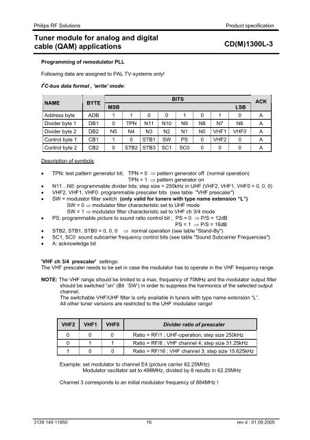
Philips RF Solutions<strong>Tuner</strong> <strong>module</strong> <strong>for</strong> <strong>analog</strong> <strong>and</strong> <strong>digital</strong><strong>cable</strong> (<strong>QAM</strong>) applicationsProduct specification<strong>CD</strong>(M)<strong>1300L</strong>-3Programming of remodulator PLLFollowing data are assigned to PAL TV-systems only!I 2 C-bus data <strong>for</strong>mat , 'write' mode:NAMEBYTEMSBBITSAddress byte ADB 1 1 0 0 1 0 1 0 ADivider byte 1 DB1 0 TPN N11 N10 N9 N8 N7 N6 ADivider byte 2 DB2 N5 N4 N3 N2 N1 N0 VHF1 VHF0 AControl byte 1 CB1 1 0 STB1 SW PS 0 VHF2 0 AControl byte 2 CB2 0 STB2 STB3 SC1 SC0 0 0 0 ADescription of symbols:• TPN: test pattern generator bit; TPN = 0 ⇒ pattern generator off (normal operation)TPN = 1 ⇒ pattern generator on• N11…N0: programmable divider bits; step size = 250kHz in UHF (VHF2, VHF1, VHF0 = 0, 0, 0)• VHF2, VHF1, VHF0 programmable prescaler bits (see table "VHF prescaler")• SW = modulator filter switch (only valid <strong>for</strong> tuners with type name extension “L”)SW = 0 ⇒ modulator filter characteristic set to UHF modeSW = 1 ⇒ modulator filter characteristic set to VHF ch 3/4 mode• PS: programmable picture to sound ratio control bit ; PS = 0 ⇒ P/S = 12dBPS = 1 ⇒ P/S = 16dB• STB2, STB1, STB0 = 0, 0, 0 ⇒ normal operation (see table "St<strong>and</strong>-By")• SC1, SC0 sound subcarrier frequency control bits (see table "Sound Subcarrier Frequencies")• A: acknowledge bitLSBACK'VHF ch 3/4 prescaler' settings:The VHF prescaler needs to be set in case the modulator has to operate in the VHF frequency range.NOTE: The VHF range should be limited to a max, frequency of 70MHz <strong>and</strong> the modulator output filtershould be switched “on” (Bit ‘SW’) in order to suppress the harmonics of the selected outputchannel.The switchable VHF/UHF filter is only available in tuners with type name extension “L”.All other tuner versions are restricted to the UHF modulator range!VHF2 VHF1 VHF0 Divider ratio of prescaler0 0 0 Ratio = RF/1 ; UHF-operation; step size 250kHz0 1 1 Ratio = RF/8 ; VHF channel 4; step size 31.25kHz1 0 0 Ratio = RF/16 ; VHF channel 3; step size 15.625kHzExample: set modulator to channel E4 (picture carrier 62.25MHz)Modulator oscillator set to 498MHz, divided by 8 results in 62.25MHzChannel 3 corresponds to an initial modulator frequency of 884MHz !3139 149 11650 16 rev d : 01.09.2005