MODEL 1703EML - THE CHAMBERLAIN ARM™ - Sparesmaster
MODEL 1703EML - THE CHAMBERLAIN ARM™ - Sparesmaster
MODEL 1703EML - THE CHAMBERLAIN ARM™ - Sparesmaster
- No tags were found...

Create successful ePaper yourself
Turn your PDF publications into a flip-book with our unique Google optimized e-Paper software.
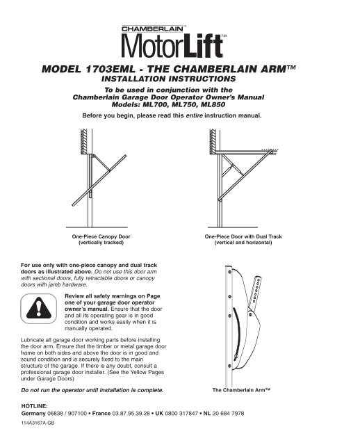
Representative Locking MechanismTo prevent damage to garage door and operator: Ensure thatturning the outside handle will not actuate ANY of the lockingmechanisms supplied with the door.• Remove all door latching mechanisms (Figure 3), andsecure any locking bars in the open position.1WARNINGCAUTIONFIGURE 324WARNING1536FIGURE 6WARNING1356• Disengage the outer trolley from the inner trolley bypulling down the manual release rope and handle(Figure 6).14• Connect and secure the extension arm to outer trolleywith the clevis pin and ring fastener provided with thegarage door operator.561. Trolley2. Clevis ring3. Bolt4. Extension Arm5. Trolley disengage lever6. Manual release34FIGURE 41. Spring2. Latch3. Door Plate4. Canopy Door5. Inside of Canopy Door6. Remove inside DoorHandle• Remove inside door handle but leave the barrel inplace in door (Figure 4).• Ensure that turning the outside handle will not actuateANY of locking mechanism supplied with the door.Failure to do so will result in serious damage to yourdoor and operator. This is not covered by theManufacturer’s Warranty.12FIGURE 5•. Unbolt the extension arm from the door arm (Figure 5).1. Connection Arm 2. Canopy Door Arm114A3167A-GB3
TemplateThe template is provided for use with two different typesof doors. Position and mark holes as directed below,based on your requirements.Template121• Position the template horizontally to match up thecenterlines of the header bracket and the template.Refer to Figure 8 or Figure 9, depending on your doorstyle.• To check, place the extension arm on the trolley intothe slot on the template. The extension arm should bestraight and in line with the garage door operator rail.FIGURE 73Note: The door arm should extend about 13mm (1/2”)over the top of the door (Figure 10 or Figure 11). Ifnot, check template and hole positions.1. Tab2. Centerline of Template3Door without a Lip213. Slot for Extension ArmAlignment TestFIGURE 8• Select and mark the (2) template holes which will allowthe mounting screws the best possible support in thedoor, (preferable hole locations into the door’s mainbracing) as shown in Figures 10/11. If possible, useadditional screws.The garage door may require additional bracing to1 2provide suitable support.31 2 3Figure FIGURE 11 1045Figure 1144556• Bend back tabs on the template (Figure 7).• Rest the bottom of the tabs on the top of the door asshown in Figure 8 (door without a lip). This providesproper vertical replacement of holes.Door with a LipFIGURE Figure 10 9216321Figure 12453Figure 12FIGURE 1148317556• For a door with a lip, as shown in Figure 9, do notbend back the tabs on the template. Instead, positionthe horizontal dotted line at the top of the lip. Thisprovides proper vertical placement of the holes.61. Top of Canopy Doorwithout Lip2. 13mm (1/2”)3. Top of Door Arm64. Screws5. Use additional screws ifpossible6. Door Arm1. Centerline of HeaderBracket2. Tab3. Template4. Canopy Door withoutLip5. Extension Arm6. Canopy Door with Lip7. Top of Template forDoor with Lip8. Top of Door with Lip114A3167A-GB4
Initial Operation:The Chamberlain Arm has been designed so that, when usedwith a Chamberlain manufactured operator, the door will open toa fully horizontal position (Figure 16).Note: The door may be designed in such a way that it does notopen to the full horizontal. Adjust the UP limit so that the doorstops at a slightly downward angle when open.Note: If safety reversing sensors (Protector System) must beinstalled, please refer to your owner´s manual beforeproceeding to Setting the limits and learning the force:Setting the limits and learning the force:When returning to your Owner’s Manual, adjust the trolley travellimits as follows:1. With the inner and outer trolley sections still disconnected,manually open your door to the horizontal position. Make amark on the rail where the end of trolley nearest to theoperator stops.2. Manually close the door and mark the rail where the end ofthe trolley nearest the door stops.3. With the inner and outer trolley sections still disconnected,activate the operator and adjust the limits following theowners manual of the garage door opener, until the innertrolley stops on the marks you made. For models ML700,ML750, ML850 please read section #15, setting limitsmanually as found in the HAVING A PROBLEM section inyour owner’s manual. While setting the door limits manually,leave door and operator disconnected at all times.4. Reconnect the inner and outer trolley sections so the door isconnected to the operator.5. Force must be learned after completion of the limit settings.For models ML700, ML750, ML850 please read section #26.6. Run the operator again to ensure the door is opening andclosing correctly.Continue with the instructions in your Owner’s Manual.Having a problem?1. Pull the manual release handle to disengage the trolley.2. Lift the door about halfway. Release the door. It should stay inplace, supported entirely by its springs.3. Raise and lower the door to see if there is any binding orsticking. If your garage door binds, sticks or is out of balance,call a professional garage door service engineer.Note: Lubricate the inside and outside of the rail.Note: In some cases you may find the door will not open fullyuntil the force has been set.Note: In rare installations, the canopy door may touch theoperator rail when closing. This is NOT the fault of the operatoror arm. If this occurs:1. Manually check the operation of the canopy door to ensurethat it is closing easily. The door must have a slight drop atthe start of closing.2. If the door is not running easily, check that the side wires arenot catching or binding on the wire guides. Move the guidesuntil the wires run free.3. Raise the operator head by about 50mm (2”) vertically sothere is a slight downward angle on the rail.4. The door spring may be over tensioned.15141. Header wall21132. Header bracket 12219FIGURE 163. Garage door opener rail1494. Ceiling5. Garage door opener15hanging brackets136. Trolley7. Extension arm8. Garage door9. Garage door spring3388121237411651012. Chamberlain 7 Arm171511Do not attempt to adjust the spring. Call a local131248WARNINGCAUTION10. Operator11.4Garage 16 door opener6manual release13. Garage door track14. Garage 11 door, should behorizontal in fully openposition15. Use limit adjustment ofgarage door opener tolevel the garage doorgarage door installing professional.The Protector System (a safety reversing sensoraccessory) must be installed, if the ChamberlainArm is used (model 770E).41676551010114A3167A-GB© 2005 Chamberlain GmbHAll rights reserved