HEGNER Accura MK4 Manual - Advanced Machinery
HEGNER Accura MK4 Manual - Advanced Machinery HEGNER Accura MK4 Manual - Advanced Machinery
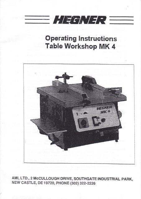
HEnffiEROperating lnstructionsTable Workshop MK aAMI, LTD.,2 MCCULLOUGH DRIVE, SOUTFIGATE INDUSTNiAI PARK,NEW CASTI_E, DE 'tg72a, pHoNE i302i 322-?:225
- Page 2 and 3: Haintenance and 0perating Instructi
- Page 4 and 5: 2. Assembly of the Machine2.L Place
- Page 6 and 7: 4. Circular Saw4.tIn order to preve
- Page 8 and 9: see 4.65600 r"p*rxr"1400 r.p.m.Atte
- Page 10 and 11: to 5.2In order to clamp cutters int
- Page 12 and 13: -6.6.1Rotary Sanding AttachmentChan
- Page 14 and 15: Io
- Page 16 and 17: 1636c9 ),687'li3v9983GK4h[i]I0t't6?
HEnffiEROperating lnstructionsTable Workshop MK aAMI, LTD.,2 MCCULLOUGH DRIVE, SOUTFIGATE INDUSTNiAI PARK,NEW CASTI_E, DE 'tg72a, pHoNE i302i 322-?:225
Haintenance and 0perating Instructions for IEGNER Precision Table llorkshop ll( 4Contents1. Safety instructions2. Assembly of the machine3. Electric lead4. Circular saw5. Router6. Botary sanding attachment7. Precision drill chuckTechnical DetailsDimensions of circular saw: diameter 150 mm (6")centre bore 20 mmRouter: 6,35 mm (114"), (8 mm optionalaccessories) ,maximum routing diameter 30 mm,36 mm using disc milling cuttersSanding plate:diameter 125 mmSanding discs:diameter 125 mmGrit 60, 80, 150, 200Extraction system:interior diameter 58 mm (2 t/4" app)
1. Saf ety InstructionsAttention ! The following general safety instructions must beobserved when operating electric tools:1.L1.21.31.41.51.6t.71.81.91.10t.tt1.721.13t.r4The work area must be kept clean and tidy. Lack of tidiness canlead to accidents.Do not use the machine in damp, wet locations or in the vicinityof inflammable liquids or gases. Ensure that the work area iswell Iit.Keep children away from the machine.Do not put too great a load on your machine - you will havemaximum safety and will receive better performance within therange of capacity indicated.Always use the correct tool. Do not use too tight a tool forheavy work. Do not use tools for work which they were not intended.Wear suitable working clothes. Do not wear loose-fitting clothingor jewellery. Loose-fitting garments can get caught in moving parts.It is recommended that non-s1ip footwear be worn when workingout of doors. Wear a hairnet if you have long hair.Use some form of eye protection (safety goggles).Use a respirator for work which creates a lot of dust.Do not use the cable for other purposes.Do not use the cable to puII the plug out of the electric socket.Protect cable from heat, oil and sharp edgesRemove the power plug whenever the machine is not in use beforeservicing and replacing parts, e.g. saw blades, router cutters etc.Do not l-eave tools inside the machine. Before switching on,check that all tools and adjusting keys have been removed.When working out of doors use only those extension cablesauthorized and designated for this purpose.Check your machine for damage. Before using the machine check thatguards are properly fitted.For your own safety use the machine only for those purposes indicatedin the operating manual. Use only those attachments which arerecommended by the manufacturer. Use of any tools or attachmentsother than those recommended in the operating manual or in thecatalogue may increase the risk of accident or injury.Never touch moving parts and fittings unless the apparatus isswitched off and disconnected at the mains.
2. Assembly of the Machine2.L Place the table workshoP on aScrew in the four rubber feetto ensure the machine is freesolid work bench or table.(1) and adjust the feetfrom rocking.2.2Attach the sanding table (2) to the left side using thetwo star knobs and attach the guard for the rotary sandingattachment (3) over the sanding disc.2.3Screw the router guard assembly onto the top of the circularsaw rip fence, with the two socket head screws using theallen key provided.
3. Electric Lead213.13.2The machine is equipped with a 3 metre 3 core cable, thi-s mustbe fitted with a standard 3 pin plug and a 10 amp fuse in the plug.The brown wire to the live connection, the blue wire to the neutralconnection, with the yellow/green wire to earth. Should there beany doubt concerning the correct fitting, consult a qualifiedelectrician. Incorrect fitting coul-d cause serious injury or evendeath by electrocution.First switch on the N0 VOLT cut-out switch item "1" (colouredwhite) into the "0N" position. The red indicator item "2" willshow that the machine is now electrically powered. To the leftof this switch there is a three position switch item "3" (colouredblack). The central positi-on is "OFF" (3.3). Turn it to the right -position 3.2 - and the saw, the drill chuck and sanding disc willoperate. It is essential to ensure that the items not in use areproperly guarded.If you turn the switch (3.1) to the left this will operate thetable routerIt is important to ensure maximum safety at all times. Thereforebefore using the router lower the circular saw below the cuttingtable and lock it in position. AIso secure the saw blade guardover the cutting table and additionally make sure the guards are inposition for the sanding disc and the drill chuck. Viceversa, whenusing the saw or other attachments be sure that the router cutter isbelow the cutting table, These measures will ensure maximum safety,should you accidentally turn the switch in the wrong direction.Finally, be sure to switch off the N0 V0LT cut-out switch when themachine is not in use.
4. Circular Saw4.tIn order to prevent accidents always remove the plug frommains supply before changing blades & cutters or makingadj ustments !Changing the saw bl-ade4.1.1, Loosen thumb screw on the guard and remove the guard fromthe riving knife.4.1..2 Remove the countersink head screws from the table insertplate, loosen the hexagon nut using the spanner. Removethe disc and saw blade - and install the alternati-ve blade.The saw blade should be kept fixed in position and thiscan be effected quite easily by jamming a plece of scrapwood against the teeth of the bl-ade.4.2 Adjustment of the riving knifeLoosen the screws (A) of the riving knife and keep a di-stanceof 2 to 3 mm between the riving knife and the saw b1ade.Then tighten the screws.The riving knife must be ,raised sufficiently so that the woodcan be moved smoothly. The riving knife prevents the cut fromclosing and jamming on the saw blade preventing a possiblereturn kick of the workpiece.4.3Release knurled nut "8" and set the cutting height as requiredby turning the knurled nut "C". Turn knurled nut "C" anticlockwise and the saw blade can be lowered even below thecutting table. Turn it clockwise to raise it.After adjusting the cutting height lock the blade in positionwith knurled nut "8".To the right of the machine and in front of the adjustment nutsis a smaIl indicator which shows the height of the saw blade,and this can be reset to obtain exactly the same height ifrequired in the future, just by making a note of the indicatorposition. E.g. this can be very useful if slot cutting andwantlng to repeat the same slot height later.4.4 Rip FenceSecure the rip fence in the grooveadjustable clamping lever. The ripsaw blade.and secure i-t by meansfence must be paraIIe1of theto theTest this by running a coin between the blade and the fenceslide it along the table, the coin should slide freely fromfront to the back of the saw blade without any excessivedifference in the clearance between the back and the front ofthe blade. The rip fence can be adjusted by means of the twoscrews (F) The fence can be mounted right or left of thesaw b1ade.andthe
Isee 4.2IiJsee 4,3
see 4.65600 r"p*rxr"1400 r.p.m.Attention:If you experience difficulties in cuttingexamine the saw blade and check whether thisrequires sharpening, and also check the belt tosee whether there is suffici-ent tension on thebelt. If necessary, please adjust with thebelt tensioning roller (see photograph).
To 4.4An additional "L" shaped rip fence can be screwed to themain rip fence which enables thin pieces of material tobe cut with precision and maximum safety as the saw bladecan be raised to a very small height ani covered with theguard.4.5Mitre FenceiThe mitre fence can be mounted right^or left_of thesaw bIade. ft permj-ts cuts between 0'and 45u in eitherdirection.4.6Two speeds are avai_1ablet. 5600 r.p.m. for wood and plastics2' 1400 r'p.m' for non-ferrous metal and ferrous metar-The machine has been set to the first speed = 5600 r.p.m.by the manufacturer. The second speed ='1400 r.p.m. isobtained by changing the special flat belt to ti-re pulley.changing alternative the belt is made easy by setting thecutting height to zero. rn order to change the belt it isfirst necessary to remove the dril1 chuc[ guard.5.5.15.2RouterThe router has a col-let dia. 6,35 mm (t/4")19 ry^i" an optional accessory) and is operated by a27.0A0 r.p.m. motor. Cylindrital cutters with maximumdia. 30 mm and di_sc-type grooving cutters with max.dia. 36 mm can be used.Clamping of the cutter into the collet
to 5.2In order to clamp cutters into the col-let, release lock nut (A)Turn handwheel (B) until stop (C) is at the top. Introduce asuitable spanner into opening (D) and hold neck of the spindle.Now tighten Lock nut using another spanner.For removing the cutters, release collet first by turninglock nut - once again as previously using the two spannersand then remove the cutter after a few turns to free thecutter.When fitting a replacement cutter, the cutter must be futlyinserted i-nto the top of the collet. In the event ofdifficulty remove both components from the machine. Then pushthe cutter ful1y into the co11et.5.35.45.5Never tighten the lock nut without a cutter inserted in thecolIet. This could compress the coll-et excessively and damageit.The guard must be adjusted to ensure cornplete cover in frontof the cutter with just sufficient clearance for the wood topass through.Adjustment of cutting depthI*8Release clamping lever (A). Turn handwheel (B) until cuttingdepth required is obtained. Then tighten lock screw (A) again-A scale at the side of the machine is used for height adjustrnentand by noting the scale position the cutter height can be resetexactly, if required to repeat the cut 1ater.
tit5.6 Working with the routerMake sure that the fence is set as crosery as possibleagainst router cutter and that the cutte"'gr"ri-is setdown as closely as possible in direction oi worksurface.Always feed the workpiece against direction of therotating cutter.lt I ". FENCE:I::iItirCUTTING DIBECTION - CORBECT!\JORKPIECEI!ftiIIrIt]rII^JoRKPIECE {i__FlIEINC0RRECT and DANGEBOUSliCutter will snatch the workpiece
-6.6.1Rotary Sanding AttachmentChanging of the sanding discsDiscRelease the two star handles of the sanding table support.Remove Velcro sanding disc. Apply new sanding disc. Fastensanding table support and guard again.4 types of sanding discs are available:grit 60 for sanding coarse workpi-ecesgrit 80 for sanding medium coarse workpiecesgrit 150 for sanding smooth workpiecesgrit 220 for sanding very smooth workpiecesMake sure that the workpiece is introduced from the front.Otherwise the workpiece will deflect upwards.Adjust the guard so that the workpiece can be pushed freely.Sanding TableSupport6.2Cleani-ng of the sanding discsff a sanding disc smears while sanding wood or paint it can becleaned with the help of an eraser or a piece of P.V.C. drainpipe.fn order to obtain the best adhesiveness possible clean theVelcro disc with a brush after use.Only use sanding discs dj-a. 125 mm (5').
7. Dri1l ChuckThe drill chuck is on the right ofa range from 1 to 10 mm (3/8" app).supplied with the machine.Be sure to remove the drilf chuck keyon the machine.8. Dust Extractionthe machine. ft hasA drill chuckrkey is/before s*itchingThe machine is equipped with a connection for an extractionsystem. usual commercial extractors by Metabo, AEG, ELU etc.can be connected.3. MaintenaneeThe machine has no lubricating points and is completelymaintenance-free ,
Io
.8 17 23 72 ?5 31 9e ?1 29 305975l9106'191022107z2€I97
1636c9 ),687'li3v9983GK4h[i]I0t't6?5!3I55>576994i6Ll:()27961n80ll707132e55/.586537865i675
ADVANCEDMACHINERY. IMPORTS LTDP.O. Box ll2 Phone 302 .322 .2226Ncw Castlc. DE 19720 Fex 302 . 322 . 3479ACCURA <strong>MK4</strong> Parts ListPart # Qty. Description Part # Qtv. Description12t'45o7I I1011121314151617't819202'l222324252627282930313233343536373839&414243444546474849'505152535411111111111111111111111111111111111111I1111'l1111111111Unit baseHousingWorktableRouter flangeCircular saw housingChuck bearing housingSander tableCircular saw arborPulley SPulley MSanding disc shaftStabilizerSawblade mounting flangeSpacerCog wheelSaw blade safety coverLow profile rip fence attachmentSawdust collection housingMiter gaugeSawblade splitterSander lable bracketExhaust portRip lenceFtip lence guidebarRip fence mounting bracketRouter columnRouler guard holder #1Router guard holder #2Router guard pin #1Router guard pin #2Clear salety shieldBoring chuck coverParallelplateParallel leverSander guardThreaded rod-.10 mmDepth gaugeControl panel cover plateMiter lence guidebarSander guard spacerSanding plateRip fence scale indicatorTable insertRip lence pressure plateSanding table tilting support plateThreaded rod-6x54 mmThreaded rod-8x85 mmTable saw rip lence scaleBouter scaleTable saw height scaleRouter exhaust portSaw belt tensionerTensioner mounting PlateMain motor555657585960616263646566676869707172737475767778798081828384858687888990919293949596979899100101102103104105106107112131111111121213125I42221113I62142211111412'l1452114Router motorCutter nutCable guideHeight adjustment wheelWing nutExhaust hose-33x240 mmCable tieSawblade height adjustment knobLocking knobWasher-18 mmFlat belt-10x420Boring chuck (3/8')Velcro coverHex nut-10 mmHex nut- 6 mmHex nut- 5 mmHex nut-10 mmHex nut- I mmHex nut-16 mmHex head screw-6 mmWasher- 6 mmAllen screw- 6 mmScrew- 5 mmAllen screw- 6 mmAllen screw- 8 mmThreaded pin- 5 mmAllen screw- 8 mmKeyCircular sawbladeAllen screw- 5 mmAllen screw- 5 mmAllen screw- 6 mmAllen screw- 4 mmMachine screw- 4 mmFlat head screw- 4 mmHex nut- 5 mmCord retainerQuick{ock lever assemblYMotor selecior switchMagnetic saletY switchWaming lightCord retainerMachine screw- 4 mmPower cordKnurled knob- 5x10 mmKnurled knob- 5x'16 mmKnurled knob- 5x20 mmNutAllen screw'6 mmKnurled knob- 5x16 mmQuickiock lever assemblYCylindricalpin- 6 mmMachine screw- 5 mm


