Wega 401 M2.40 FKW - EWM Hightec Welding GmbH
Wega 401 M2.40 FKW - EWM Hightec Welding GmbH Wega 401 M2.40 FKW - EWM Hightec Welding GmbH
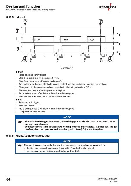
Design and functionMIG/MAG functional sequences / operating modes5.11.5 IntervalFigure 5-171. Start• Press and hold torch trigger.• Shielding gas is expelled (gas pre-flows).• Wire-feed motor runs at "creep-start speed".• Arc ignites after the wire electrode makes contact with the workpiece; welding current flows.• Changeover to the pre-selected wire speed after the set ignition time (tZn).• The wire feed stops after the pulse time expires.• Arc is extinguished after the wire burn-back time elapses.• The process is repeated after the pause time elapses.2. End• Release torch trigger.• Wire feed stops.• Arc is extinguished after the wire burn-back time elapses.• Gas post-flow time elapses.NOTEWhen the torch trigger is released, the welding process is also interrupted even beforethe spot time elapses.With fast tacking (time between two welding process under approx. 1.5 seconds) the gaspre-flow, the creep process and also the ignition time (tZn) are not required.5.11.6 MIG/MAG automatic cut-outNOTEThe welding machine ends the ignition process or the welding process with an• Ignition fault (no welding current flows within 5 s after the start signal).• Arc interruption (arc is intrerupted for longer than 2 s).54099-005224-EW50108.11.2011
6 Maintenance, care and disposalMaintenance, care and disposalGeneralDANGERRisk of injury from electric shock!Cleaning machines that are not disconnected from the mains can lead to seriousinjuries!• Disconnect the machine completely from the mains.• Remove the mains plug!• Wait for 4 minutes until the capacitors have discharged!6.1 GeneralWhen used in the specified environmental conditions and under normal operating conditions, thismachine is largely maintenance-free and requires a minimum of care.There are some points, which should be observed, to guarantee fault-free operation of your weldingmachine. Among these are regular cleaning and checking as described below, depending on the pollutionlevel of the environment and the length of time the unit is in use.6.2 Maintenance work, intervals6.2.1 Daily maintenance tasks• Check correct mounting of the wire spool.• Mains supply lead and its strain relief• Welding current cables (check that they are fitted correctly and secured)• Gas tubes and their switching equipment (solenoid valve)• Gas cylinder securing elements• Operating, message, safety and adjustment devices (Functional test)• Other, general condition6.2.2 Monthly maintenance tasks• Casing damage (front, rear and side walls)• Wheels and their securing elements• Transport elements (strap, lifting lugs, handle)• Selector switches, command devices, emergency stop devices, voltage reducing devices, messageand control lamps• Check coolant tubes and their connections for impurities• Check that the wire guide elements (inlet nipple, wire guide tube) are fitted securely.6.2.3 Annual test (inspection and testing during operation)NOTEThe welding machine may only be tested by competent, capable personsl.A capable person is one who, because of his training, knowledge and experience, isable to recognise the dangers that can occur while testing welding power sources aswell as possible subsequent damage and who is able to implement the required safetyprocedures.For further information, please see the accompanying supplementary sheets "Machineand Company Data, Maintenance and Testing, Warranty"!A periodic test according to IEC 60974-4 "Periodic inspection and test" has to be carried out. In additionto the regulations on testing given here, the relevant local laws and regulations must also be observed.099-005224-EW50108.11.201155
- Page 6: Safety instructionsNotes on the use
- Page 9: Safety instructionsGeneralWARNINGEx
- Page 12 and 13: Safety instructionsTransport and in
- Page 14 and 15: Safety instructionsAmbient conditio
- Page 16 and 17: Machine description - quick overvie
- Page 18 and 19: Machine description - quick overvie
- Page 20 and 21: Machine description - quick overvie
- Page 22 and 23: Machine description - quick overvie
- Page 24 and 25: Machine description - quick overvie
- Page 26 and 27: Design and functionGeneral5 Design
- Page 28 and 29: Design and functionMains connection
- Page 30 and 31: Design and functionWelding torch co
- Page 32 and 33: Design and functionWelding torch an
- Page 34 and 35: Design and functionShielding gas su
- Page 36 and 37: Design and functionShielding gas su
- Page 38 and 39: Design and functionInserting the wi
- Page 40 and 41: Design and functionSelect welding t
- Page 42 and 43: Design and functionSelect welding t
- Page 44 and 45: Design and functionSelect welding t
- Page 46 and 47: Design and functionSelect welding t
- Page 48 and 49: Design and functionSelect welding t
- Page 50 and 51: Design and functionMIG/MAG function
- Page 52 and 53: Design and functionMIG/MAG function
- Page 57 and 58: Rectifying faultsCustomer checklist
- Page 59 and 60: Rectifying faultsResetting the cont
- Page 61 and 62: Technical dataWega 4018 Technical d
- Page 63 and 64: Replaceable partsWire feed rollers1
- Page 65 and 66: Appendix ARecommended settings11 Ap
Design and functionMIG/MAG functional sequences / operating modes5.11.5 IntervalFigure 5-171. Start• Press and hold torch trigger.• Shielding gas is expelled (gas pre-flows).• Wire-feed motor runs at "creep-start speed".• Arc ignites after the wire electrode makes contact with the workpiece; welding current flows.• Changeover to the pre-selected wire speed after the set ignition time (tZn).• The wire feed stops after the pulse time expires.• Arc is extinguished after the wire burn-back time elapses.• The process is repeated after the pause time elapses.2. End• Release torch trigger.• Wire feed stops.• Arc is extinguished after the wire burn-back time elapses.• Gas post-flow time elapses.NOTEWhen the torch trigger is released, the welding process is also interrupted even beforethe spot time elapses.With fast tacking (time between two welding process under approx. 1.5 seconds) the gaspre-flow, the creep process and also the ignition time (tZn) are not required.5.11.6 MIG/MAG automatic cut-outNOTEThe welding machine ends the ignition process or the welding process with an• Ignition fault (no welding current flows within 5 s after the start signal).• Arc interruption (arc is intrerupted for longer than 2 s).54099-005224-EW50108.11.2011


