Wega 401 M2.40 FKW - EWM Hightec Welding GmbH
Wega 401 M2.40 FKW - EWM Hightec Welding GmbH Wega 401 M2.40 FKW - EWM Hightec Welding GmbH
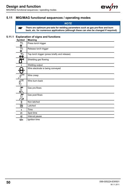
Design and functionMIG/MAG functional sequences / operating modes5.11 MIG/MAG functional sequences / operating modesNOTEThere are optimum pre-sets for welding parameters such as gas pre-flow and burnback, etc. for numerous applications (although these can also be changed if required).5.11.1 Explanation of signs and functionsSymbol MeaningPress torch triggerRelease torch triggerTap torch trigger (press briefly and release)Shielding gas flowingIWelding outputWire electrode is being conveyedWire creepWire burn-backGas pre-flowsGas post-flowsNon-latchedLatchedtt1t2tZnTimeSpot timeInterval pauseIgnition time50099-005224-EW50108.11.2011
Design and functionMIG/MAG functional sequences / operating modes5.11.2 Non-latched operationFigure 5-14Step 1• Press and hold torch trigger.• Shielding gas is expelled (gas pre-flows).• Wire feed motor runs at "creep speed".• Arc ignites after the wire electrode makes contact with the workpiece; welding current flows.• Changeover to the pre-selected wire speed after the set ignition time (tZn).Step 2• Release torch trigger.• WF motor stops.• Arc is extinguished after the pre-selected wire burn-back time elapses.• Gas post-flow time elapses.099-005224-EW50108.11.201151
- Page 6: Safety instructionsNotes on the use
- Page 9: Safety instructionsGeneralWARNINGEx
- Page 12 and 13: Safety instructionsTransport and in
- Page 14 and 15: Safety instructionsAmbient conditio
- Page 16 and 17: Machine description - quick overvie
- Page 18 and 19: Machine description - quick overvie
- Page 20 and 21: Machine description - quick overvie
- Page 22 and 23: Machine description - quick overvie
- Page 24 and 25: Machine description - quick overvie
- Page 26 and 27: Design and functionGeneral5 Design
- Page 28 and 29: Design and functionMains connection
- Page 30 and 31: Design and functionWelding torch co
- Page 32 and 33: Design and functionWelding torch an
- Page 34 and 35: Design and functionShielding gas su
- Page 36 and 37: Design and functionShielding gas su
- Page 38 and 39: Design and functionInserting the wi
- Page 40 and 41: Design and functionSelect welding t
- Page 42 and 43: Design and functionSelect welding t
- Page 44 and 45: Design and functionSelect welding t
- Page 46 and 47: Design and functionSelect welding t
- Page 48 and 49: Design and functionSelect welding t
- Page 52 and 53: Design and functionMIG/MAG function
- Page 54 and 55: Design and functionMIG/MAG function
- Page 57 and 58: Rectifying faultsCustomer checklist
- Page 59 and 60: Rectifying faultsResetting the cont
- Page 61 and 62: Technical dataWega 4018 Technical d
- Page 63 and 64: Replaceable partsWire feed rollers1
- Page 65 and 66: Appendix ARecommended settings11 Ap
Design and functionMIG/MAG functional sequences / operating modes5.11 MIG/MAG functional sequences / operating modesNOTEThere are optimum pre-sets for welding parameters such as gas pre-flow and burnback, etc. for numerous applications (although these can also be changed if required).5.11.1 Explanation of signs and functionsSymbol MeaningPress torch triggerRelease torch triggerTap torch trigger (press briefly and release)Shielding gas flowingI<strong>Welding</strong> outputWire electrode is being conveyedWire creepWire burn-backGas pre-flowsGas post-flowsNon-latchedLatchedtt1t2tZnTimeSpot timeInterval pauseIgnition time50099-005224-EW50108.11.2011


