Wega 401 M2.40 FKW - EWM Hightec Welding GmbH
Wega 401 M2.40 FKW - EWM Hightec Welding GmbH Wega 401 M2.40 FKW - EWM Hightec Welding GmbH
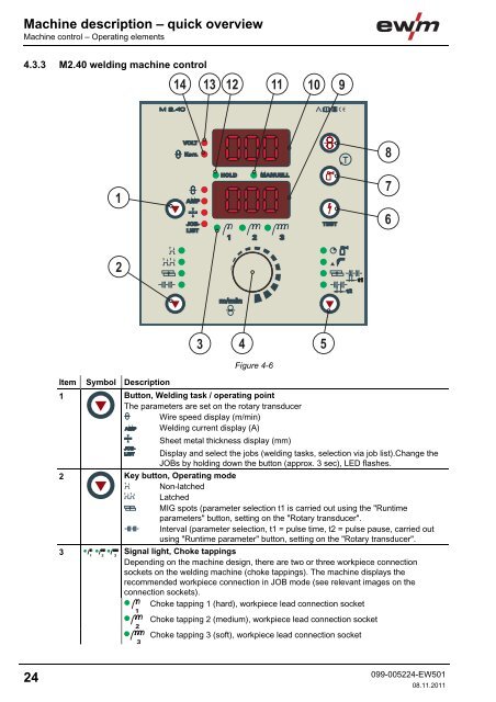
Machine description – quick overviewMachine control – Operating elements4.3.3 M2.40 welding machine controlItem Symbol Description 0Figure 4-61 Button, Welding task / operating pointThe parameters are set on the rotary transducerWire speed display (m/min)Welding current display (A)Sheet metal thickness display (mm)Display and select the jobs (welding tasks, selection via job list).Change theJOBs by holding down the button (approx. 3 sec), LED flashes.2 Key button, Operating modeNon-latchedLatchedMIG spots (parameter selection t1 is carried out using the "Runtimeparameters" button, setting on the "Rotary transducer".Interval (parameter selection, t1 = pulse time, t2 = pulse pause, carried outusing "Runtime parameter" button, setting on the "Rotary transducer".3Signal light, Choke tappingsDepending on the machine design, there are two or three workpiece connectionsockets on the welding machine (choke tappings). The machine displays therecommended workpiece connection in JOB mode (see relevant images on theconnection sockets).Choke tapping 1 (hard), workpiece lead connection socketChoke tapping 2 (medium), workpiece lead connection socketChoke tapping 3 (soft), workpiece lead connection socket24099-005224-EW50108.11.2011
Machine description – quick overviewMachine control – Operating elementsItem Symbol Description 04 Rotary dial, Wire speed / welding parameter settingInfinite adjustment of the wire speed or welding current, sheet metal thickness, JOBand runtime parameters such as gas post-flows, wire burn-back, etc.5 "Runtime parameters" buttonThe parameters are set on the rotary transducerGas post-flow time (0.0 s to 10.0 s)Wire burn-back (-50% to +50%)Spot time / pulse time (0.1 s to 5.0 s)Pulse pause (0.1 s to 2.0 s)6 Button, Test welding parametersPress the button and set the required welding voltage on the step switch at the sametime (the open-circuit voltage will be shown in the upper display; the wire speed,welding current or panel thickness in the lower display).7 Button, Gas testThe welding voltage and wire feed remain off when testing and setting the gas flow.Pressing the key button once causes shielding gas to flow for approx. 25 seconds. Thebutton can be pressed again at any time to cancel the process.8 Button, Wire inchingFor inching the wire electrode when changing the wire spool(speed = 6.0 m/min, constant).The welding wire is inched into the tube package with the current off and without gasbeing expelled.This ensures a high degree of safety for the welder by preventing accidental ignition ofthe arc.9 Lower displayDisplay of wire feed speed, welding current, sheet metal thickness, JOB number andruntime parameters.10 Upper displayDisplay of the welding voltage, correction value for the wire speed or parameterdesignations for runtime parameters.11 Signal light, MANUALSignal light is on when the machine is not in JOB mode. All parameter settings arecarried out "manually" by the user (JOB 0).12 Signal light, HOLDLit: Display shows the last parameters used for welding.Not lit: Display shows the setpoint values or current values during welding.13 Signal light VoltageOn when the welding voltage or open circuit voltage is displayed.14 Signal light, Wire correctionOn when the correction value of the wire speed is being displayed.099-005224-EW50108.11.201125
- Page 6: Safety instructionsNotes on the use
- Page 9: Safety instructionsGeneralWARNINGEx
- Page 12 and 13: Safety instructionsTransport and in
- Page 14 and 15: Safety instructionsAmbient conditio
- Page 16 and 17: Machine description - quick overvie
- Page 18 and 19: Machine description - quick overvie
- Page 20 and 21: Machine description - quick overvie
- Page 22 and 23: Machine description - quick overvie
- Page 26 and 27: Design and functionGeneral5 Design
- Page 28 and 29: Design and functionMains connection
- Page 30 and 31: Design and functionWelding torch co
- Page 32 and 33: Design and functionWelding torch an
- Page 34 and 35: Design and functionShielding gas su
- Page 36 and 37: Design and functionShielding gas su
- Page 38 and 39: Design and functionInserting the wi
- Page 40 and 41: Design and functionSelect welding t
- Page 42 and 43: Design and functionSelect welding t
- Page 44 and 45: Design and functionSelect welding t
- Page 46 and 47: Design and functionSelect welding t
- Page 48 and 49: Design and functionSelect welding t
- Page 50 and 51: Design and functionMIG/MAG function
- Page 52 and 53: Design and functionMIG/MAG function
- Page 54 and 55: Design and functionMIG/MAG function
- Page 57 and 58: Rectifying faultsCustomer checklist
- Page 59 and 60: Rectifying faultsResetting the cont
- Page 61 and 62: Technical dataWega 4018 Technical d
- Page 63 and 64: Replaceable partsWire feed rollers1
- Page 65 and 66: Appendix ARecommended settings11 Ap
Machine description – quick overviewMachine control – Operating elements4.3.3 <strong>M2.40</strong> welding machine controlItem Symbol Description 0Figure 4-61 Button, <strong>Welding</strong> task / operating pointThe parameters are set on the rotary transducerWire speed display (m/min)<strong>Welding</strong> current display (A)Sheet metal thickness display (mm)Display and select the jobs (welding tasks, selection via job list).Change theJOBs by holding down the button (approx. 3 sec), LED flashes.2 Key button, Operating modeNon-latchedLatchedMIG spots (parameter selection t1 is carried out using the "Runtimeparameters" button, setting on the "Rotary transducer".Interval (parameter selection, t1 = pulse time, t2 = pulse pause, carried outusing "Runtime parameter" button, setting on the "Rotary transducer".3Signal light, Choke tappingsDepending on the machine design, there are two or three workpiece connectionsockets on the welding machine (choke tappings). The machine displays therecommended workpiece connection in JOB mode (see relevant images on theconnection sockets).Choke tapping 1 (hard), workpiece lead connection socketChoke tapping 2 (medium), workpiece lead connection socketChoke tapping 3 (soft), workpiece lead connection socket24099-005224-EW50108.11.2011


