Wega 401 M2.40 FKW - EWM Hightec Welding GmbH
Wega 401 M2.40 FKW - EWM Hightec Welding GmbH
Wega 401 M2.40 FKW - EWM Hightec Welding GmbH
- No tags were found...

Create successful ePaper yourself
Turn your PDF publications into a flip-book with our unique Google optimized e-Paper software.
Safety instructionsNotes on the use of these operating instructions2 Safety instructions2.1 Notes on the use of these operating instructionsDANGERWorking or operating procedures which must be closely observed to prevent imminentserious and even fatal injuries.• Safety notes include the "DANGER" keyword in the heading with a general warning symbol.• The hazard is also highlighted using a symbol on the edge of the page.WARNINGWorking or operating procedures which must be closely observed to prevent seriousand even fatal injuries.• Safety notes include the "WARNING" keyword in the heading with a general warningsymbol.• The hazard is also highlighted using a symbol in the page margin.CAUTIONWorking or operating procedures which must be closely observed to prevent possibleminor personal injury.• The safety information includes the "CAUTION" keyword in its heading with a generalwarning symbol.• The risk is explained using a symbol on the edge of the page.CAUTIONWorking and operating procedures which must be followed precisely to avoid damagingor destroying the product.• The safety information includes the "CAUTION" keyword in its heading without a generalwarning symbol.• The hazard is explained using a symbol at the edge of the page.NOTESpecial technical points which users must observe.• Notes include the "NOTE" keyword in the heading without a general warning symbol.Instructions and lists detailing step-by-step actions for given situations can be recognised via bulletpoints, e.g.:• Insert the welding current lead socket into the relevant socket and lock.6099-005224-EW50108.11.2011
Safety instructionsGeneral2.3 GeneralDANGERElectric shock!<strong>Welding</strong> machines use high voltages which can result in potentially fatal electric shocksand burns on contact. Even low voltages can cause you to get a shock and lead toaccidents.• Do not touch any live parts in or on the machine!• Connection cables and leads must be free of faults!• Switching off alone is not sufficient!• Place welding torch and stick electrode holder on an insulated surface!• The unit should only be opened by specialist staff after the mains plug has been unplugged!• Only wear dry protective clothing!• Wait for 4 minutes until the capacitors have discharged!Electromagnetic fields!The power source may cause electrical or electromagnetic fields to be produced whichcould affect the correct functioning of electronic equipment such as IT or CNC devices,telecommunication lines, power cables, signal lines and pacemakers.• Observe the maintenance instructions! (see Maintenance and Testing chapter)• Unwind welding leads completely!• Shield devices or equipment sensitive to radiation accordingly!• The correct functioning of pacemakers may be affected (obtain advice from a doctor ifnecessary).Do not carry out any unauthorised repairs or modifications!To avoid injury and equipment damage, the unit must only be repaired or modified byspecialist, skilled persons!The warranty becomes null and void in the event of unauthorised interference.• Appoint only skilled persons for repair work (trained service personnel)!WARNINGRisk of accidents if these safety instructions are not observed!Non-observance of these safety instructions is potentially fatal!• Carefully read the safety information in this manual!• Observe the accident prevention regulations in your country.• Inform persons in the working area that they must observe the regulations!Risk of injury due to radiation or heat!Arc radiation results in injury to skin and eyes.Contact with hot workpieces and sparks results in burns.• Use welding shield or welding helmet with the appropriate safety level (depending on theapplication)!• Wear dry protective clothing (e.g. welding shield, gloves, etc.) according to the relevantregulations in the country in question!• Protect persons not involved in the work against arc beams and the risk of glare usingsafety curtains!8099-005224-EW50108.11.2011
Safety instructionsGeneralWARNINGExplosion risk!Apparently harmless substances in closed containers may generate excessive pressurewhen heated.• Move containers with inflammable or explosive liquids away from the working area!• Never heat explosive liquids, dusts or gases by welding or cutting!Smoke and gases!Smoke and gases can lead to breathing difficulties and poisoning. In addition, solventvapour (chlorinated hydrocarbon) may be converted into poisonous phosgene due tothe ultraviolet radiation of the arc!• Ensure that there is sufficient fresh air!• Keep solvent vapour away from the arc beam field!• Wear suitable breathing apparatus if appropriate!Fire hazard!Flames may arise as a result of the high temperatures, stray sparks, glowing-hot partsand hot slag produced during the welding process.Stray welding currents can also result in flames forming!• Check for fire hazards in the working area!• Do not carry any easily flammable objects such as matches or lighters.• Keep appropriate fire extinguishing equipment to hand in the working area!• Thoroughly remove any residue of flammable substances from the workpiece beforestarting welding.• Only continue work on welded workpieces once they have cooled down.Do not allow to come into contact with flammable material!• Connect welding leads correctly!CAUTIONNoise exposure!Noise exceeding 70 dBA can cause permanent hearing damage!• Wear suitable ear protection!• Persons located within the working area must wear suitable ear protection!CAUTIONObligations of the operator!The respective national directives and laws must be observed for operation of themachine!• National implementation of the framework directive (89/391/EWG), as well as theassociated individual directives.• In particular, directive (89/655/EWG), on the minimum regulations for safety and healthprotection when staff members use equipment during work.• The regulations regarding work safety and accident prevention for the respective country.• Setting up and operating the machine according to IEC 60974-9.• Check at regular intervals that users are working in a safety-conscious way.• Regular checks of the machine according to IEC 60974-4.099-005224-EW50108.11.20119
Safety instructionsGeneralCAUTIONEMC Machine ClassificationIn accordance with IEC 60974-10, welding machines are grouped in two electromagneticcompatibility classes (see technical data):Class A machines are not intended for use in residential areas where the power supply comesfrom the low-voltage public mains network. When ensuring the electromagnetic compatibility ofclass A machines, difficulties can arise in these areas due to interference not only in the supplylines but also in the form of radiated interference.Class B machines fulfil the EMC requirements in industrial as well as residential areas,including residential areas connected to the low-voltage public mains network.Setting up and operatingWhen operating arc welding systems, in some cases, electro-magnetic interference can occuralthough all of the welding machines comply with the emission limits specified in the standard.The user is responsible for any interference caused by welding.In order to evaluate any possible problems with electromagnetic compatibility in thesurrounding area, the user must consider the following: (see also EN 60974-10 Appendix A)• Mains, control, signal and telecommunication lines• Radios and televisions• Computers and other control systems• Safety equipment• The health of neighbouring persons, especially if they have a pacemaker or wear a hearingaid• Calibration and measuring equipment• The immunity to interference of other equipment in the surrounding area• The time of day at which the welding work must be carried outRecommendations for reducing interference emission• Mains connection, e.g. additional mains filter or shielding with a metal tube• Maintenance of the arc welding equipment• <strong>Welding</strong> leads should be as short as possible and run closely together along the ground• Potential equalization• Earthing of the workpiece. In cases where it is not possible to earth the workpiece directly,it should be connected by means of suitable capacitors.• Shielding from other equipment in the surrounding area or the entire welding system099-005224-EW50108.11.201111
Safety instructionsTransport and installation2.4 Transport and installationWARNINGIncorrect handling of shielding gas cylinders!Incorrect handling of shielding gas cylinders can result in serious and even fatal injury.• Observe the instructions from the gas manufacturer and in any relevant regulationsconcerning the use of compressed air!• Place shielding gas cylinders in the holders provided for them and secure with fixingdevices.• Avoid heating the shielding gas cylinder!CAUTIONRisk of tipping!There is a risk of the machine tipping over and injuring persons or being damaged itselfduring movement and set up. Tilt resistance is guaranteed up to an angle of 10°(according to EN 60974-A2).• Set up and transport the machine on level, solid ground!• Secure add-on parts using suitable equipment!• Replace damaged wheels and their fixing elements!• Fix external wire feed units during transport (avoid uncontrolled rotation)!Damage due to supply lines not being disconnected!During transport, supply lines which have not been disconnected (mains supply leads,control leads, etc.) may cause hazards such as connected equipment tipping over andinjuring persons!• Disconnect supply lines!CAUTIONEquipment damage when not operated in an upright position!The units are designed for operation in an upright position!Operation in non-permissible positions can cause equipment damage.• Only transport and operate in an upright position!12099-005224-EW50108.11.2011
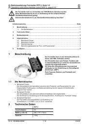
Safety instructionsTransport and installation2.4.1 Lifting by craneDANGERRisk of injury during lifting by crane!When lifting the equipment by crane, serious injuries can be inflicted by fallingequipment or add-on units.• Transport on all lifting lugs at the same time(see Fig. Lifting principle)!• Ensure that there is an even load distribution! Onlyuse ring chains or suspension ropes of the samelength!• Observe the lifting principle (see Fig.)!• Remove all accessory components before lifting(e.g. shielding gas cylinders, tool boxes, wire feedunits, etc.)!• Avoid jerky movements when raising or lowering!• Use shackles and load hooks of the appropriate size!min. 1 m75 °Fig. Lifting principleRisk of injury due to unsuitable ring screws!In case of improper use of ring screws or the use of unsuitable ring screws, personscan be seriously damaged by falling equipment or add-on components!• The ring screw must be completely screwed in!• The ring screw must be positioned flat onto and in full contact with the supporting surfaces!• Check that the ring screws are securely fastened before use and check for any damage(corrosion, deformation)!• Do not use or screw in damaged ring screws!• Avoid lateral loading of the ring screws!099-005224-EW50108.11.201113
Safety instructionsAmbient conditions2.5 Ambient conditionsCAUTIONInstallation site!The machine must not be operated in the open air and must only be set up andoperated on a suitable, stable and level base!• The operator must ensure that the ground is non-slip and level, and provide sufficientlighting for the place of work.• Safe operation of the machine must be guaranteed at all times.CAUTIONEquipment damage due to dirt accumulation!Unusually high quantities of dust, acid, corrosive gases or substances may damage theequipment.• Avoid high volumes of smoke, vapour, oil vapour and grinding dust!• Avoid ambient air containing salt (sea air)!Non-permissible ambient conditions!Insufficient ventilation results in a reduction in performance and equipment damage.• Observe the ambient conditions!• Keep the cooling air inlet and outlet clear!• Observe the minimum distance of 0.5 m from obstacles!2.5.1 In operationTemperature range of the ambient air:• -20 °C to +40 °CRelative air humidity:• Up to 50% at 40 °C• Up to 90% at 20 °C2.5.2 Transport and storageStorage in an enclosed space, temperature range of the ambient air:• -25 °C to +55 °CRelative air humidity• Up to 90% at 20 °C14099-005224-EW50108.11.2011
Intended useApplications3 Intended useThis machine has been manufactured according to the latest developments in technology and currentregulations and standards. It must only be operated in line with the instructions on correct usage.WARNINGHazards due to improper usage!Hazards may arise for persons, animals and material objects if the equipment is notused correctly. No liability is accepted for any damages arising from improper usage!• The equipment must only be used in line with proper usage and by trained or expert staff!• Do not modify or convert the equipment improperly!3.1 Applications3.1.1 MIG/MAG standard weldingMetal arc welding using a wire electrode whereby gas from an external source surrounds the arc and themolten pool to protect them from the atmosphere.3.2 Documents which also apply3.2.1 WarrantyNOTEFor further information, please see the accompanying supplementary sheets "Machineand Company Data, Maintenance and Testing, Warranty"!3.2.2 Declaration of ConformityThe designated machine conforms to EC Directives and standards in terms of its designand construction:• EC Low Voltage Directive (2006/95/EC),• EC EMC Directive (2004/108/EC),This declaration shall become null and void in the event of unauthorised modifications, improperlyconducted repairs, non-observance of the deadlines for the repetition test and / or non-permittedconversion work not specifically authorised by the manufacturer.The original copy of the declaration of conformity is enclosed with the unit.3.2.3 <strong>Welding</strong> in environments with increased electrical hazardsIn compliance with IEC / DIN EN 60974, VDE 0544 the machines can be used inenvironments with an increased electrical hazard.3.2.4 Service documents (spare parts and circuit diagrams)DANGERDo not carry out any unauthorised repairs or modifications!To avoid injury and equipment damage, the unit must only be repaired or modified byspecialist, skilled persons!The warranty becomes null and void in the event of unauthorised interference.• Appoint only skilled persons for repair work (trained service personnel)!Original copies of the circuit diagrams are enclosed with the unit.Spare parts can be obtained from the relevant authorised dealer.099-005224-EW50108.11.201115
Machine description – quick overviewFront view4 Machine description – quick overview4.1 Front viewNOTECoolant tank and quick connect coupling of coolant supply and return are only fitted inmachines with water cooling.Figure 4-116099-005224-EW50108.11.2011
Machine description – quick overviewFront viewItem Symbol Description 01 Lifting lug2 Carrying handle3 Cooling air inlet4 Wheels, guide castors5 Connection socket, workpiece lead"Hard" choke tapping6 Connection socket, workpiece lead"Medium" choke tapping7 Connection socket, workpiece leadChoke tapping "soft"8 Coolant tank9 Coolant tank cap10 Automatic cut-out of coolant pump key buttonpress to reset a triggered fuse11 Central connection for welding torch (Euro)Integrated welding current, shielding gas and torch trigger12 Machine controlSee Machine control – operating elements chapter13 <strong>Welding</strong> voltage step switch, final settingTo finally adjust the welding voltage (select the option to roughly preset the weldingvoltage first)14 <strong>Welding</strong> voltage step switch, presettingTo roughly preset the welding voltage15 Main switch, machine on/off16 Collective interference signal lightFor error messages, see the "Rectifying faults" chapter17 Ready for operation signal lightSignal light on when the machine is switched on and ready for operation18 Quick connect coupling (red)coolant return19 Quick connect coupling (blue)coolant supply099-005224-EW50108.11.201117
Machine description – quick overviewRear view4.2 Rear viewFigure 4-218099-005224-EW50108.11.2011
Machine description – quick overviewRear viewItem Symbol Description 01 Wire feed unit cover lock2 Cover for wire feed unit and operating elements3 Securing elements for shielding gas cylinder (strap/chain)4 Wire spool inspection windowCheck wire supply5 Cooling air outlet6 Bracket for shielding gas cylinder7 Wheels, fixed castors8 Mains connection cable9 Connecting nipple G¼, shielding gas connection10 Key button, automatic cutoutWire feed motor supply voltage fusepress to reset a triggered fuse11 Button, Automatic cut-out of fan motorPress to reset tripped circuit breaker099-005224-EW50108.11.201119
Machine description – quick overviewMachine control – Operating elements4.3 Machine control – Operating elements4.3.1 <strong>Welding</strong> machine control M1.02Item Symbol Description 0Figure 4-31 Rotary dial, Wire speed settingInfinite adjustment of the wire speed.2 Rotary dial, Spot and interval timesInfinite adjustment of the welding time (0-2s) in "Spots and interval" operating mode3 "Operating mode" selector switchChangeover between non-latched, latched, spot, interval4 Rotary dial, Pause timeInfinite adjustment of the pause time (0–2s) in "Interval" operating mode5 Ready for operation signal lightSignal light on when the machine is switched on and ready for operation20099-005224-EW50108.11.2011
Machine description – quick overviewMachine control – Operating elements4.3.1.1 Internal operating elementsNOTEThe maximum possible machine configuration is given in the text description.If necessary, the optional connection may need to be retrofitted (see "Accessories"chapter).• Unlock the right-hand cover on the machine.• Tilt the cover forwards, then remove upwards.There are other operating elements for parameter setting on the machine.Figure 4-4All details in percent relate to the values stored in the characteristics.Item Symbol Description 01Rotary dial, Wire creep (optional)0-15 +15+/- 30%-30+302 Key Button, Wire inchingCurrentless wire inching3 "Gas post-flow time" trimmerSetting range 0.2-10 s4 Trimmer, Burn-back+/- 50%099-005224-EW50108.11.201121
Machine description – quick overviewMachine control – Operating elements4.3.2 M2.20 welding machine controlItem Symbol Description 0Figure 4-51 Key button, Operating modeNon-latchedLatchedMIG spots (parameter selection t1 is carried out using the "Runtimeparameters" button, setting on the "Rotary transducer".Interval (parameter selection, t1 = pulse time, t2 = pulse pause, carried outusing "Runtime parameter" button, setting on the "Rotary transducer".2 AMP Current signal lightLights when the current is shown on the display.3 Rotary dial, Wire speed/welding parameter settingContinuous adjustment of the wire speed or welding current and setting of runtimeparameters such as gas post-flows, wire burn-back, etc.4 "Runtime parameters" buttonThe parameters are set on the rotary transducerGas post-flow time (0.0 s to 10.0 s)Wire burn-back (-50% to +50%)Spot time / pulse time (0.1 s to 5.0 s)Pulse pause (0.1 s to 2.0 s)5 Lower displayDisplay of wire feed speed, welding current and runtime parameters.22099-005224-EW50108.11.2011
Machine description – quick overviewMachine control – Operating elementsItem Symbol Description 06 Button, Gas testThe welding voltage and wire feed remain off when testing and setting the gas flow.Pressing the key button once causes shielding gas to flow for approx. 25 seconds. Thebutton can be pressed again at any time to cancel the process.7 Button, Wire inchingFor inching the wire electrode when changing the wire spool(speed = 6.0 m/min, constant).The welding wire is inched into the tube package with the current off and without gasbeing expelled.This ensures a high degree of safety for the welder by preventing accidental ignition ofthe arc.8 Upper, displayDisplays welding voltage or person who designated the runtime parameters9 Signal light, HOLDLit: Display shows the last parameters used for welding.Not lit: Display shows the setpoint values or current values during welding.10 Signal light, Wire speedLights when the wire speed is shown on the display.099-005224-EW50108.11.201123
Machine description – quick overviewMachine control – Operating elements4.3.3 <strong>M2.40</strong> welding machine controlItem Symbol Description 0Figure 4-61 Button, <strong>Welding</strong> task / operating pointThe parameters are set on the rotary transducerWire speed display (m/min)<strong>Welding</strong> current display (A)Sheet metal thickness display (mm)Display and select the jobs (welding tasks, selection via job list).Change theJOBs by holding down the button (approx. 3 sec), LED flashes.2 Key button, Operating modeNon-latchedLatchedMIG spots (parameter selection t1 is carried out using the "Runtimeparameters" button, setting on the "Rotary transducer".Interval (parameter selection, t1 = pulse time, t2 = pulse pause, carried outusing "Runtime parameter" button, setting on the "Rotary transducer".3Signal light, Choke tappingsDepending on the machine design, there are two or three workpiece connectionsockets on the welding machine (choke tappings). The machine displays therecommended workpiece connection in JOB mode (see relevant images on theconnection sockets).Choke tapping 1 (hard), workpiece lead connection socketChoke tapping 2 (medium), workpiece lead connection socketChoke tapping 3 (soft), workpiece lead connection socket24099-005224-EW50108.11.2011
Machine description – quick overviewMachine control – Operating elementsItem Symbol Description 04 Rotary dial, Wire speed / welding parameter settingInfinite adjustment of the wire speed or welding current, sheet metal thickness, JOBand runtime parameters such as gas post-flows, wire burn-back, etc.5 "Runtime parameters" buttonThe parameters are set on the rotary transducerGas post-flow time (0.0 s to 10.0 s)Wire burn-back (-50% to +50%)Spot time / pulse time (0.1 s to 5.0 s)Pulse pause (0.1 s to 2.0 s)6 Button, Test welding parametersPress the button and set the required welding voltage on the step switch at the sametime (the open-circuit voltage will be shown in the upper display; the wire speed,welding current or panel thickness in the lower display).7 Button, Gas testThe welding voltage and wire feed remain off when testing and setting the gas flow.Pressing the key button once causes shielding gas to flow for approx. 25 seconds. Thebutton can be pressed again at any time to cancel the process.8 Button, Wire inchingFor inching the wire electrode when changing the wire spool(speed = 6.0 m/min, constant).The welding wire is inched into the tube package with the current off and without gasbeing expelled.This ensures a high degree of safety for the welder by preventing accidental ignition ofthe arc.9 Lower displayDisplay of wire feed speed, welding current, sheet metal thickness, JOB number andruntime parameters.10 Upper displayDisplay of the welding voltage, correction value for the wire speed or parameterdesignations for runtime parameters.11 Signal light, MANUALSignal light is on when the machine is not in JOB mode. All parameter settings arecarried out "manually" by the user (JOB 0).12 Signal light, HOLDLit: Display shows the last parameters used for welding.Not lit: Display shows the setpoint values or current values during welding.13 Signal light VoltageOn when the welding voltage or open circuit voltage is displayed.14 Signal light, Wire correctionOn when the correction value of the wire speed is being displayed.099-005224-EW50108.11.201125
Design and functionGeneral5 Design and function5.1 GeneralWARNINGRisk of injury from electric shock!Contact with live parts, e.g. welding current sockets, is potentially fatal!• Follow safety instructions on the opening pages of the operating instructions.• Commissioning may only be carried out by persons who have the relevant expertise ofworking with arc welding machines!• Connection and welding leads (e.g. electrode holder, welding torch, workpiece lead,interfaces) may only be connected when the machine is switched off!CAUTIONRisk of burns on the welding current connection!If the welding current connections are not locked, connections and leads heat up andcan cause burns, if touched!• Check the welding current connections every day and lock by turning in clockwise direction,if necessary.Risk of injury due to moving parts!The wire feed units are equipped with moving parts, which can trap hands, hair,clothing or tools and thus injure persons!• Do not reach into rotating or moving parts or drive components!• Keep casing covers closed during operation!Risk of injury due to welding wire escaping in an unpredictable manner!<strong>Welding</strong> wire can be conveyed at very high speeds and, if conveyed incorrectly, mayescape in an uncontrolled manner and injure persons!• Before mains connection, set up the complete wire guide system from the wire spool to thewelding torch!• Remove the pressure rollers from the wire feed unit if no welding torch is fitted!• Check wire guide at regular intervals!• Keep all casing covers closed during operation!Risk from electrical current!If welding is carried out alternately using different methods and if a welding torch andan electrode holder remain connected to the machine, the open-circuit/welding voltageis applied simultaneously on all cables.• The torch and the electrode holder should therefore always be placed on an insulatedsurface before starting work and during breaks.26099-005224-EW50108.11.2011
Design and functionTransport and installationCAUTIONDamage due to incorrect connection!Accessory components and the power source itself can be damaged by incorrectconnection!• Only insert and lock accessory components into the relevant connection socket when themachine is switched off.• Comprehensive descriptions can be found in the operating instructions for the relevantaccessory components.• Accessory components are detected automatically after the power source is switched on.Using protective dust caps!Protective dust caps protect the connection sockets and therefore the machine againstdirt and damage.• The protective dust cap must be fitted if there is no accessory component being operatedon that connection.• The cap must be replaced if faulty or if lost!5.2 Transport and installationCAUTIONInstallation site!The machine must not be operated in the open air and must only be set up andoperated on a suitable, stable and level base!• The operator must ensure that the ground is non-slip and level, and provide sufficientlighting for the place of work.• Safe operation of the machine must be guaranteed at all times.5.3 Workpiece lead, generalCAUTIONRisk of burns due to incorrect connection of the workpiece lead!Paint, rust and dirt on the connection restrict the power flow and may lead to straywelding currents.Stray welding currents may cause fires and injuries!• Clean the connections!• Fix the workpiece lead securely!• Do not use structural parts of the workpiece as a return lead for the welding current!• Take care to ensure faultless power connections!5.4 Machine coolingTo obtain an optimal duty cycle from the power components, the following precautions should beobserved:• Ensure that the working area is adequately ventilated.• Do not obstruct the air inlets and outlets of the machine.• Do not allow metal parts, dust or other objects to get into the machine.099-005224-EW50108.11.201127
Design and functionMains connection5.5 Mains connectionDANGERHazard caused by improper mains connection!An improper mains connection can cause injuries or damage property!• Only use machine with a plug socket that has a correctly fitted protective conductor.• If a mains plug must be fitted, this may only be carried out by an electrician in accordancewith the relevant national provisions or regulations (any phase sequence for three-phasemachines)!• Mains plug, socket and lead must be checked regularly by an electrician!• When operating the generator always ensure it is earthed as stated in the operatinginstructions. The resulting network has to be suitable for operating devices according toprotection class 1.5.5.1 Mains configurationNOTEThe machine may be connected to:• a three-phase system with four conductors and an earthed neutral conductor• a three-phase system with three conductors of which any one can be earthed,e.g. the outer conductorFigure 5-1LegendItem Designation Colour codeL1 Outer conductor 1 blackL2 Outer conductor 2 brownL3 Outer conductor 3 greyN Neutral conductor bluePE Protective conductor green-yellowCAUTIONOperating voltage - mains voltage!The operating voltage shown on the rating plate must be consistent with the mainsvoltage, in order to avoid damage to the machine!• For mains fuse protection, please refer to the “Technical data” chapter!• Insert mains plug of the switched-off machine into the appropriate socket.28099-005224-EW50108.11.2011
Design and function<strong>Welding</strong> torch cooling system5.6 <strong>Welding</strong> torch cooling systemNOTEOnly with water-cooled welding machines!5.6.1 GeneralCAUTIONCoolant mixtures!Mixtures with other liquids or the use of unsuitable coolants result in material damageand renders the manufacturer's warranty void!• Only use the coolant described in this manual (overview of coolants).• Do not mix different coolants.• When changing the coolant, the entire volume of liquid must be changed.Insufficient frost protection in the welding torch coolant!Depending on the ambient conditions, different liquids are used for cooling the weldingtorch (see overview of coolants).Coolants with frost protection (KF 37E or KF 23E) must be checked regularly to ensurethat the frost protection is adequate to prevent damage to the machine or the accessorycomponents.• The coolant must be checked for adequate frost protection with the TYP 1 frost protectiontester (see accessories).• Replace coolant as necessary if frost protection is inadequate!NOTEThe disposal of coolant must be carried out according to official regulations andobserving the relevant safety data sheets (German waste code number: 70104)!• Coolant must not be disposed of together with household waste.• Coolant must not be discharged into the sewerage system.• Recommended cleaning agent: water, if necessary with cleaning agent added.5.6.2 List of coolantsThe following coolants may be used (for item nos., please see the Accessories chapter):CoolantTemperature rangeKF 23E (Standard) -10 °C to +40 °CKF 37E -20 °C to +10 °CDKF 23E (for plasma machines) 0 °C to +40 °C099-005224-EW50108.11.201129
Design and function<strong>Welding</strong> torch cooling system5.6.3 Adding coolantThe unit is supplied ex works with a minimum level of coolant.Item Symbol Description 01 Coolant tank cap2 Coolant filter sieve3 Coolant tank4 "Min" markMinimum coolant levelFigure 5-2• Unscrew and remove the coolant tank sealing cover.• Check filter sieve insert for dirt, clean if necessary and reinsert into position.• Top up coolant to the filter sieve insert, close sealing cover again.NOTEAfter the initial filling, wait for at least one minute when the machine is switched on sothat the tube package is filled with coolant completely and without bubbles.With frequent changes of torch and during the initial filling process, the cooling unittank should be topped up as necessary.The level of coolant must never fall below the “min” mark.If there is less coolant in the coolant tank than the minimum required you may need tovent the coolant circuit. In this case the welding machine will automatically shut downthe coolant pump and signal an error, see chapter "Rectifying faults".30099-005224-EW50108.11.2011
Design and function<strong>Welding</strong> torch and workpiece line connection5.7 <strong>Welding</strong> torch and workpiece line connectionCAUTIONEquipment damage due to improperly connected coolant lines!If the coolant lines are not connected or a gas-cooled welding torch is used, the coolantcircuit is interrupted and equipment damage can occur.• Connect all coolant lines correctly!• When using a gas-cooled welding torch, add a tube bridge to the coolant circuit (seechapter “Accessories”).NOTEPrepare welding torch according to the welding task in hand (see operating instructionsfor the torch).Figure 5-3099-005224-EW50108.11.201131
Design and function<strong>Welding</strong> torch and workpiece line connectionItem Symbol Description 01 <strong>Welding</strong> torch2 <strong>Welding</strong> torch hose package3 Central connection for welding torch (Euro)Integrated welding current, shielding gas and torch trigger4 Quick connect coupling (red)coolant return5 Quick connect coupling (blue)coolant supply6 Workpiece7 Workpiece lead8 Connection socket, workpiece lead"Hard" choke tapping9 Connection socket, workpiece lead"Medium" choke tapping10 Connection socket, workpiece leadChoke tapping "soft"• Insert the central plug for the welding torch into the central connector and screw together with crownnut.• Insert the cable plug of the workpiece lead into the connection socket for workpiece lead 1, 2 or 3(depending on the application or shielding gas used) and lock by turning to the right.If fitted:• Lock connecting nipples of the cooling water tubes into the corresponding quick connect couplings:Return line red to quick connect coupling, red (coolant return) andsupply line blue to quick connect coupling, blue (coolant supply).32099-005224-EW50108.11.2011
Design and functionShielding gas supply5.8 Shielding gas supply5.8.1 Connecting the shielding gas supplyWARNINGRisk of injury due to improper handling of shielding gas cylinders!Improper handling and insufficient securing of shielding gas cylinderscan cause serious injuries!• Secure shielding gas cylinders using the standard fastening elements onthe unit (chain/belt)!• The fastening elements must tightly enclose the shielding gas cylinder!• Attach the fastening elements within the upper half of the shielding gascylinder!• Do not attach any element to the shielding gas cylinder valve!• Observe the instructions from the gas manufacturer and any relevantregulations concerning the use of compressed air!• Avoid heating the shielding gas cylinder!CAUTIONFaults in the shielding gas supply.An unhindered shielding gas supply from the shielding gas cylinder to the weldingtorch is a fundamental requirement for optimum welding results. In addition, a blockedshielding gas supply may result in the welding torch being destroyed.• Always re-fit the yellow protective cap when not using the shielding gas connection.• All shielding gas connections must be gas tight.NOTEBefore connecting the pressure regulator to the gas cylinder, open the cylinder valvebriefly to expel any dirt.099-005224-EW50108.11.201133
Design and functionShielding gas supply• Place the shielding gas cylinder into the relevant cylinder bracket.• Secure the shielding gas cylinder using a securing chain.Figure 5-4Item Symbol Description 01 Pressure regulator2 Shielding gas cylinder3 Output side of the pressure regulator4 Cylinder valve• Tighten the pressure regulator screw connection on the gas bottle valve to be gas-tight.• Screw gas hose connection crown nut onto the output side of the pressure regulator.34099-005224-EW50108.11.2011
Design and functionShielding gas supplyItem Symbol Description 0Figure 5-51 G¼” connecting nippleShielding gas connection on the pressure regulator.2 Securing elements for shielding gas cylinder (strap/chain)3 Bracket for shielding gas cylinder099-005224-EW50108.11.201135
Design and functionShielding gas supply5.8.2 Setting the shielding gas quantity<strong>Welding</strong> processRecommended shielding gas quantityMAG weldingMIG brazingMIG welding (aluminium)TIGWire diameter x 11.5 = l/minWire diameter x 11.5 = l/minWire diameter x 13.5 = l/min (100 % argon)Gas nozzle diameter in mm corresponds to l/min gas throughputHelium-rich gas mixtures require a higher gas volume!The table below can be used to correct the gas volume calculated where necessary:Shielding gasFactor75% Ar/25% He 1.1450% Ar/50% He 1.3525% Ar/75% He 1.75100% He 3.16NOTEIncorrect shielding gas setting!If the shielding gas setting is too low or too high, this can introduce air to the weld pooland may cause pores to form.• Adjust the shielding gas quantity to suit the welding task!36099-005224-EW50108.11.2011
Design and functionInserting the wire electrode5.9 Inserting the wire electrode5.9.1 Inserting the wire spoolNOTEStandard D300 wire spool holder can be used. Adapters (see accessories) are requiredwhen using standardised basket coils (DIN 8559).12Item Symbol Description 01 Carrier pinFor fixing the wire spool2 Knurled nutFor fixing the wire spoolFigure 5-6• Loosen knurled nut from spool holder.• Fix welding wire reel onto the spool holder so that the carrier pin locks into the spool bore.• Fasten wire spool using knurled nut.CAUTIONRisk of injury due to incorrectly secured wire spool.If the wire spool is not secured properly, it may come loose from the wire spool holderand fall to the ground, causing damage to the machine and injuries.• Securely fasten the wire spool to the wire spool holder using the knurled nut.• Before you start working, always check the wire spool is securely fastened.099-005224-EW50108.11.201137
Design and functionInserting the wire electrode5.9.2 Changing the wire feed rollersNOTEUnsatisfactory welding results due to faulty wire feeding!Wire feed rollers must be suitable for the diameter of the wire and the material.• Check the roller label to verify that the rollers are suitable for the wire diameter.Turn or change if necessary!• use V-groove rollers with for steel wires and other hard wires,• use U-groove rollers for aluminium wires and other soft, alloyed wires.• Slide new drive rollers into place so that the diameter of the wire used is visible on the drive roller.• Screw the drive rollers in place with knurled screws.5.9.3 Inching the wire electrodeFigure 5-7CAUTIONRisk of injury due to welding wire escaping in an unpredictable manner!<strong>Welding</strong> wire can be conveyed at very high speeds and, if conveyed incorrectly, mayescape in an uncontrolled manner and injure persons!• Before mains connection, set up the complete wire guide system from the wire spool to thewelding torch!• Remove the pressure rollers from the wire feed unit if no welding torch is fitted!• Check wire guide at regular intervals!• Keep all casing covers closed during operation!CAUTIONExtensive wear due to incorrect contact pressure!Incorrect contact pressure will cause extensive wear of the wire feed rollers!• With the adjusting nuts of the pressure units set the contact pressure so that the wireelectrode is conveyed but will still slip through if the wire spool jams.• Set the contact pressure of the front rollers (in wire feed direction) to a higher value!38099-005224-EW50108.11.2011
Design and functionInserting the wire electrode12543Figure 5-8Item Symbol Description 01 Pressure units2 Clamping units3 Wire feed nipple4 Guide tube5 Capillary tube or plastic core with support tube, depending on the torchequipment• Extend and lay out the torch hose package.• Unfasten pressure units and fold out (clamping units and pressure rollers will automatically flipupwards).• Unwind welding wire carefully from the wire spool and insert through the wire inlet nipple over the driveroller grooves and the guide pipe into the capillary tube and Teflon core using guide pipe.• Press the clamping element with the pressure roller back downwards and fold the wire units back upagain (wire electrode should be in the groove on the drive roller).• Set the contact pressure with the adjusting nuts of the pressure unit.• Press the wire inching button until the wire electrode projects out of the welding torch.NOTEThe inching speed is infinitely adjustable by simultaneously pressing the wire inchingbutton and turning the wire speed rotary dial. The display shows the selected inchingspeed.099-005224-EW50108.11.201139
Design and functionSelect welding task5.9.4 Spool brake setting1Item Symbol Description 0Figure 5-91 Allen screwSecuring the wire spool retainer and adjustment of the spool brake• Tighten the Allen screw (8 mm) in the clockwise direction to increase the braking effect.NOTETighten the spool brake until the wire spool no longer turns when the wire feed motor stops butwithout it jamming during operation!5.10 Select welding task5.10.1 <strong>Welding</strong> machine control M1.025.10.1.1 Setting the operating point (welding output)This control works according to the twin-knob operation principle. To set the operating point, only the wirespeed and the welding voltage need to be set according to the material and the electrode diameter.OperatingelementActionResultWire speed setting<strong>Welding</strong> voltage setting5.10.1.2 <strong>Welding</strong> parameter ignition time "tZn" diagramNOTEIn the ignition time, the wire feed continues to run at creep speed after the arc is ignited;the ignition behaviour is improved with the optimum setting.The process described below is always used if there is a pause between welding processes ofnot less than 1.5 seconds.40099-005224-EW50108.11.2011
Design and functionSelect welding taskFigure 5-10Legend with an explanation of symbols can be found in the MIG/MAG function sequences /operating modes chapter.099-005224-EW50108.11.201141
Design and functionSelect welding task5.10.2 M2.20 welding machine control5.10.2.1 Setting the operating point (welding output)This control works according to the twin-knob operation principle. To set the operating point, only the wirespeed and the welding voltage need to be set according to the material and the electrode diameter.OperatingelementAction ResultWire speed setting<strong>Welding</strong> voltage setting5.10.2.2 Setting the operating mode and runtime parametersNOTEThe parameter values set are preset in the JOB and can be modified if necessary.OperatingelementActionn xn xResultSelect operating mode:Non-latchedLatchedSpotsIntervalSelect welding parameter:Set gas post-flow time "GnS"(0.0 s to 10.0 s)Set wire burn-back time "drb" (-50% to 50%)Spot/interval time "t1" (0.1 s to 5.0 s)Interval/pause "t2" (0.1 s to 2.0 s)The selected parameter is shown on the displaySet the parameter chosen42099-005224-EW50108.11.2011
Design and functionSelect welding task5.10.2.3 Setting the expert parametersNOTEThe parameter values set are preset in the JOB and can be modified if necessary.OperatingelementAction1 xResultSelect expert parameters.The key combination must be pressed within 3 seconds.1 x2 xn xSelect expert parameters:Gas pre-flow time "GvS" (0 s to 10 s)Wire creep speed "On" 0.5 – 24 m/minIgnition time "tZn" (0 ms to 500 ms)The selected parameter is shown on the display.Set the parameter chosen.5.10.2.4 Explanation of symbolsSymbol Meaning"GnS" - Gas post-flows"drb" - Wire burn-back"t1" - Spot time"t2" - Interval time"GvS" - Gas pre-flows"On" - Wire creep"tZn" - Ignition time"tyP" - Machine type (type table, see chapter "Rectifying faults")099-005224-EW50108.11.201143
Design and functionSelect welding task5.10.2.5 <strong>Welding</strong> parameter ignition time "tZn" diagramNOTEIn the ignition time, the wire feed continues to run at creep speed after the arc is ignited;the ignition behaviour is improved with the optimum setting.The process described below is always used if there is a pause between welding processes ofnot less than 1.5 seconds.Figure 5-11Legend with an explanation of symbols can be found in the MIG/MAG function sequences /operating modes chapter.44099-005224-EW50108.11.2011
Design and functionSelect welding task5.10.3 <strong>M2.40</strong> welding machine control5.10.3.1 Select JOB number (welding task)This microprocessor-controlled control works according to the one-dial operation principle.Only the gas type, material type and wire electrode diameter should be set as the JOB number on thecontrol, as well as welding output via the step switch. This defines the welding task and the systemspecifies the optimum wire feed speed for the required operating point after the "Test button" is pressed.These settings are retained after the machine is switched off. After switching on again, the parameterspreviously set can be used to continue welding.The user has the option to correct the wire feed speed according to the welding task or individualrequirements.The welding task setting can also be made using the two-dial operation principle, however. To do this, setthe "JOB 0" (manual / no program) from the JOB list, the welding voltage on the step switch, and the wirespeed on the rotary dial. Other parameters are set as described under "Using synergic mode".Operating Action ResultelementX xSelect "JOB". When the "JOB" LED lights, press and holddown the button.2 sec. "JOB" LED flashes.The welder uses the filler material inserted and the connected shielding gas to select the JOB numberaccording to the "JOB-LIST". The "JOB-LIST" is a sticker fixed near the wire feed drive unit.Set JOB number (0-24).1 xConfirm selection.094-010488-00500Massivdraht / Solid WireMaterialSG2/3G3/4 Si1CrNiAlMgAlSiGasAr82/18Ar98/2Ar100Ar100%CO 100 2Wire0,8 1,0 1,2 1,6Job-Nr.1526374891317101418111519121620Massivdraht / Solid WireAl99Ar10021222324Manuell / no program0Figure 5-12099-005224-EW50108.11.201145
Design and functionSelect welding task5.10.3.2 Setting the operating point (welding output)NOTEThe operating point setting in JOB "0" (manual) is carried out as described in the chapterof the same name for control M2.4x. The following settings are therefore only intendedfor work in JOBs 1-24.OperatingelementActionn xResultSelect the parameter via which the welding output is to be set:using the panel thicknessusing the wire speedusing the welding current+ +Hold down the "TEST" button and at the same time set the operatingpoint on the step switch.The display shows the required parameters and the open circuitvoltage.If the "Volt" and "Wire feed correction" diodes are flashing, this indicatesan error (e.g. short circuit between torch and workpiece, inductivityerror, etc). To correct the error, press "TEST" again.If the operating mode has already been selected, all the necessary settings will have beenactivated and welding can be started.5.10.3.3 Setting the wire correctionThe wire speed (arc length) can be modified using the wire correction if required.OperatingelementAction ResultSet the wire correction value46099-005224-EW50108.11.2011
Design and functionSelect welding task5.10.3.4 Setting the operating mode and runtime parametersNOTEThe parameter values set are preset in the JOB and can be modified if necessary.OperatingelementActionn xn xResultSelect operating mode:Non-latchedLatchedSpotsIntervalSelect welding parameter:Set gas post-flow time "GnS"(0.0 s to 10.0 s)Set wire burn-back time "drb" (-50% to 50%)Spot/interval time "t1" (0.1 s to 5.0 s)Interval/pause "t2" (0.1 s to 2.0 s)The selected parameter is shown on the displaySet the parameter chosen099-005224-EW50108.11.201147
Design and functionSelect welding task5.10.3.5 Setting the expert parametersNOTEThe parameter values set are preset in the JOB and can be modified if necessary.OperatingelementAction1 xResultSelect expert parameters.The key combination must be pressed within 3 seconds.1 x2 xn xSelect expert parameters:Gas pre-flow time "GvS" (0 s to 10 s)Wire creep speed "On" 0.5 – 24 m/minIgnition time "tZn" (0 ms to 500 ms)The selected parameter is shown on the display.Set the parameter chosen.5.10.3.6 Explanation of symbolsSymbol Meaning"GnS" - Gas post-flows"drb" - Wire burn-back"t1" - Spot time"t2" - Interval time"GvS" - Gas pre-flows"On" - Wire creep"tZn" - Ignition time"tyP" - Machine type (type table, see chapter "Rectifying faults")48099-005224-EW50108.11.2011
Design and functionSelect welding task5.10.3.7 <strong>Welding</strong> parameter ignition time "tZn" diagramNOTEIn the ignition time, the wire feed continues to run at creep speed after the arc is ignited;the ignition behaviour is improved with the optimum setting.The factory setting is that the ignition time is already optimally preset for various materials. Theprocess described below is always used if there is a pause between welding processes of notless than 1.5 seconds.Figure 5-13Legend with an explanation of symbols can be found in the MIG/MAG function sequences /operating modes chapter.099-005224-EW50108.11.201149
Design and functionMIG/MAG functional sequences / operating modes5.11 MIG/MAG functional sequences / operating modesNOTEThere are optimum pre-sets for welding parameters such as gas pre-flow and burnback, etc. for numerous applications (although these can also be changed if required).5.11.1 Explanation of signs and functionsSymbol MeaningPress torch triggerRelease torch triggerTap torch trigger (press briefly and release)Shielding gas flowingI<strong>Welding</strong> outputWire electrode is being conveyedWire creepWire burn-backGas pre-flowsGas post-flowsNon-latchedLatchedtt1t2tZnTimeSpot timeInterval pauseIgnition time50099-005224-EW50108.11.2011
Design and functionMIG/MAG functional sequences / operating modes5.11.2 Non-latched operationFigure 5-14Step 1• Press and hold torch trigger.• Shielding gas is expelled (gas pre-flows).• Wire feed motor runs at "creep speed".• Arc ignites after the wire electrode makes contact with the workpiece; welding current flows.• Changeover to the pre-selected wire speed after the set ignition time (tZn).Step 2• Release torch trigger.• WF motor stops.• Arc is extinguished after the pre-selected wire burn-back time elapses.• Gas post-flow time elapses.099-005224-EW50108.11.201151
Design and functionMIG/MAG functional sequences / operating modes5.11.3 4-cycle operationFigure 5-15Step 1• Press and hold torch trigger.• Shielding gas is expelled (gas pre-flows).• Wire feed motor runs at "creep speed".• Arc ignites when the wire electrode makes contact with the workpiece; welding current flows.• Changeover to the pre-selected wire speed after the set ignition time (tZn).Step 2• Release torch trigger (no effect).Step 3• Press torch trigger (no effect).Step 4• Release torch trigger.• WF motor stops.• Arc is extinguished after the pre-selected wire burn-back time elapses.• Gas post-flow time elapses.52099-005224-EW50108.11.2011
Design and functionMIG/MAG functional sequences / operating modes5.11.4 Spot weldingFigure 5-161. Start• Press and hold torch trigger.• Shielding gas is expelled (gas pre-flows).• Wire feed motor runs at "creep speed".• Arc ignites after the wire electrode makes contact with the workpiece; welding current flows.• Changeover to the pre-selected wire speed after the set ignition time (tZn).• The WF stops after the set spot welding time elapses.• Arc is extinguished after the pre-selected wire burn-back time elapses.• Gas post-flow time elapses.2. End• Release torch trigger.NOTEWhen the torch trigger is released, the welding process is also interrupted even beforethe spot time elapses.With fast tacking (time between two welding process under approx. 1.5 seconds) the gaspre-flow, the creep process and also the ignition time (tZn) are not required.099-005224-EW50108.11.201153
Design and functionMIG/MAG functional sequences / operating modes5.11.5 IntervalFigure 5-171. Start• Press and hold torch trigger.• Shielding gas is expelled (gas pre-flows).• Wire-feed motor runs at "creep-start speed".• Arc ignites after the wire electrode makes contact with the workpiece; welding current flows.• Changeover to the pre-selected wire speed after the set ignition time (tZn).• The wire feed stops after the pulse time expires.• Arc is extinguished after the wire burn-back time elapses.• The process is repeated after the pause time elapses.2. End• Release torch trigger.• Wire feed stops.• Arc is extinguished after the wire burn-back time elapses.• Gas post-flow time elapses.NOTEWhen the torch trigger is released, the welding process is also interrupted even beforethe spot time elapses.With fast tacking (time between two welding process under approx. 1.5 seconds) the gaspre-flow, the creep process and also the ignition time (tZn) are not required.5.11.6 MIG/MAG automatic cut-outNOTEThe welding machine ends the ignition process or the welding process with an• Ignition fault (no welding current flows within 5 s after the start signal).• Arc interruption (arc is intrerupted for longer than 2 s).54099-005224-EW50108.11.2011
6 Maintenance, care and disposalMaintenance, care and disposalGeneralDANGERRisk of injury from electric shock!Cleaning machines that are not disconnected from the mains can lead to seriousinjuries!• Disconnect the machine completely from the mains.• Remove the mains plug!• Wait for 4 minutes until the capacitors have discharged!6.1 GeneralWhen used in the specified environmental conditions and under normal operating conditions, thismachine is largely maintenance-free and requires a minimum of care.There are some points, which should be observed, to guarantee fault-free operation of your weldingmachine. Among these are regular cleaning and checking as described below, depending on the pollutionlevel of the environment and the length of time the unit is in use.6.2 Maintenance work, intervals6.2.1 Daily maintenance tasks• Check correct mounting of the wire spool.• Mains supply lead and its strain relief• <strong>Welding</strong> current cables (check that they are fitted correctly and secured)• Gas tubes and their switching equipment (solenoid valve)• Gas cylinder securing elements• Operating, message, safety and adjustment devices (Functional test)• Other, general condition6.2.2 Monthly maintenance tasks• Casing damage (front, rear and side walls)• Wheels and their securing elements• Transport elements (strap, lifting lugs, handle)• Selector switches, command devices, emergency stop devices, voltage reducing devices, messageand control lamps• Check coolant tubes and their connections for impurities• Check that the wire guide elements (inlet nipple, wire guide tube) are fitted securely.6.2.3 Annual test (inspection and testing during operation)NOTEThe welding machine may only be tested by competent, capable personsl.A capable person is one who, because of his training, knowledge and experience, isable to recognise the dangers that can occur while testing welding power sources aswell as possible subsequent damage and who is able to implement the required safetyprocedures.For further information, please see the accompanying supplementary sheets "Machineand Company Data, Maintenance and Testing, Warranty"!A periodic test according to IEC 60974-4 "Periodic inspection and test" has to be carried out. In additionto the regulations on testing given here, the relevant local laws and regulations must also be observed.099-005224-EW50108.11.201155
Rectifying faultsCustomer checklist7 Rectifying faultsAll products are subject to rigorous production checks and final checks. If, despite this, something fails towork at any time, please check the product using the following flowchart. If none of the fault rectificationprocedures described leads to the correct functioning of the product, please inform your authoriseddealer.7.1 Customer checklistCollective interference signal light illuminates Excess temperature, welding machine Allow the machine to cool down whilst still switched on <strong>Welding</strong> current monitoring device triggered (stray welding currents flowing across the protectiveearth). The error must be reset by switching the machine off and on again. <strong>Welding</strong> wire is touching electrically conductive casing parts (check wire guide, has the weldingwire sprung off the wire spool?). Check for a correct mounting of the welding lead. Fit the feeder clamp of the welding lead asclose as possible to the arc.Coolant error/no coolant flowing Insufficient coolant flow Check coolant level and refill if necessary Air in the coolant circuit see chapter "Vent coolant circuit"Wire feed problems Contact tip blocked Clean, spray with anti-spatter spray and replace if necessary Setting the spool brake (see "Setting the spool brake" chapter) Check settings and correct if necessary Setting pressure units (see "Inching wire electrodes" chapter) Check settings and correct if necessary Worn wire rolls Check and replace if necessary Wire feed motor without supply voltage (automatic cutout triggered by overloading) Reset triggered fuse (rear of the power source) by pressing the key button Kinked hose packages Extend and lay out the torch hose package Wire guide core or spiral is dirty or worn Clean core or spiral; replace kinked or worn coresFunctional errors Machine control without displaying the signal lights after switching on Phase failure > check mains connection (fuses) No welding performance Phase failure > check mains connection (fuses) Various parameters cannot be set Entry level is blocked, disable access lock (see chapter entitled "Lock welding parametersagainst unauthorised access") Connection problems Make control lead connections and check that they are fitted correctly. Loose welding current connections Tighten power connections on the torch and/or on the workpiece Tighten contact tip/collet correctly099-005224-EW50108.11.201157
Rectifying faultsCheck the machine type setting7.2 Check the machine type settingOnly with the M2.xx machine control.NOTEAfter switching on, the machine type that has been set is displayed for a short time,denoted as "tyP".If the machine type displayed does not match the machine, you have to correct thissetting.„tyP 00“ Saturn 251„tyP d00“ Saturn 256„tyP 01“ Saturn 301„tyP r01“ Mira 301 (M2.xx)„tyP 02“ Saturn 351„tyP d02“ <strong>Wega</strong> 351, Saturn 351 DG„tyP d03” <strong>Wega</strong> <strong>401</strong>,451„tyP d04” <strong>Wega</strong> 501,6017.2.1 Setting the machine typeOperating Action ResultelementSwitch off the welding machine.1 x+m/min1 xPress and hold both buttons.Switch on the welding machine, "Anl" is shown on the display.Whilst "Anl" is being displayed, set the machine type:0 Saturn 251 KGE1 Saturn 301 KGE2 Saturn 351 KGE3 decompact (DK), all; <strong>Wega</strong>, all7 Mira 301 KGE58099-005224-EW50108.11.2011
Rectifying faultsResetting the control (Reset all)7.3 Resetting the control (Reset all)NOTEM2.xx controlThe first action should always be to check and if necessary correct the machine typesetting.All user settings will be overwritten with factory settings and must therefore be checkedafterwards, or set up again!After resetting the machine control to the factory settings, it is essential that the machinetype used is checked and reset if necessary.OperatingelementAction1 xResultSwitch off the welding machine.Press and hold both buttons.t1+t21 xSwitch on the welding machine, "rES" is shown briefly on the display.099-005224-EW50108.11.201159
Rectifying faultsVent coolant circuit7.4 Vent coolant circuitNOTEIf there is less coolant in the coolant tank than the minimum required you may need tovent the coolant circuit. In this case the welding machine will automatically shut downthe coolant pump and signal an error, see chapter "Rectifying faults".To vent the cooling system always use the blue coolant connection, which is located asdeep as possible inside the system (close to the coolant tank)!60099-005224-EW50108.11.2011
Technical data<strong>Wega</strong> <strong>401</strong>8 Technical dataNOTEPerformance specifications and guarantee only in connection with original spare andreplacement parts!8.1 <strong>Wega</strong> <strong>401</strong><strong>Wega</strong> <strong>401</strong> FKG <strong>401</strong> <strong>FKW</strong>Switching steps 24 (2 x 12)Setting range for welding current30 A to 400 ASetting range for welding voltage15.5 V to 34.0 VDuty cycle (25 °C)400 A (70%)300 A (100%)Duty cycle (40 °C)400 A (60%)300 A (100%)Open circuit voltage15.5 V to 45 VMains connection leadH07RN-F4G4Mains voltage (tolerances) 3 x 400 V (+/- 15%)Frequency50/60 HzMains fuse3 x 25 A(safety fuse, slow-blow)Max. connected load19.2 kVARecommended generator power26 kVA<strong>Welding</strong> lead70 mm²cosϕ 0.95Cooling capacity at 1 l/min - 1200 WTank capacity (max.) - 9 lFlow rate (max.) - 5 l/minOutlet pressure (max.) - 3.5 barWeight DW 145 kg 185 kgDimensions L x W x H in mm 1100 x 550 x 940Insulation class/protectionH/IP 23classificationAmbient temperature -20 °C to +40 °CMachine/torch cooling Fan/gas Fan/waterEMC classAConstructed to standard IEC 60974-1, -5, -10/IEC 60974-1, -2, -5, -10/099-005224-EW50108.11.201161
AccessoriesOptions9 AccessoriesNOTEPerformance-dependent accessories like torches, workpiece leads, electrode holders orintermediate hose packages are available from your authorised dealer.9.1 OptionsType Designation Item no.ON Filter W Retrofit option contamination filter for air inlet 092-002091-00000ON LB Wheels 160x40MM Retrofit option for locking brake for machine wheels 092-002110-00000ON Holder Gas Bottle
Replaceable partsWire feed rollers10 Replaceable parts10.1 Wire feed rollersCAUTIONDamage due to the use of non-genuine parts!The manufacturer's warranty becomes void if non-genuine parts are used!• Only use system components and options (power sources, welding torches, electrodeholders, remote controls, spare parts and replacement parts, etc.) from our range ofproducts!• Only insert and lock accessory components into the relevant connection socket when themachine is switched off.10.1.1 Wire feed rollers for steel wireType Designation Item no.FE 2DR4R 0,6+0,8 Drive rollers, 37 mm, steel 092-000839-00000FE 2DR4R 0,8+1,0 Drive rollers, 37 mm, steel 092-000840-00000FE 2DR4R 0,9+1,2 Drive rollers, 37 mm, steel 092-000841-00000FE 2DR4R 1,0+1,2 Drive rollers, 37 mm, steel 092-000842-00000FE 2DR4R 1,2+1,6 Drive rollers, 37 mm, steel 092-000843-00000FE/AL 2GR4R Pressure rollers, smooth, 37mm 092-000844-0000010.1.2 Wire feed rollers for aluminium wireType Designation Item no.AL 4ZR4R 0,8+1,0 Twin rollers, 37 mm, for aluminium 092-000869-00000AL 4ZR4R 1,0+1,2 Twin rollers, 37 mm, for aluminium 092-000848-00000AL 4ZR4R 1,2+1,6 Twin rollers, 37 mm, for aluminium 092-000849-00000AL 4ZR4R 2,4+3,2 Twin rollers, 37 mm, for aluminium 092-000870-0000010.1.3 Wire feed rollers for cored wireType Designation Item no.ROE 2DR4R 0,8/0,9+0,8/0,9 Drive rollers, 37 mm, cored wire 092-000834-00000ROE 2DR4R 1,0/1,2+1,4/1,6 Drive rollers, 37 mm, cored wire 092-000835-00000ROE 2DR4R 1,4/1,6+2,0/2,4 Drive rollers, 37 mm, cored wire 092-000836-00000ROE 2DR4R 2,8+3,2 Drive rollers, 37 mm, cored wire 092-000837-00000ROE 2GR4R Pressure rollers, knurled, 37mm 092-000838-00000099-005224-EW50108.11.201163
Replaceable partsWire feed rollers10.1.4 Conversion setsType Designation Item no.URUE VERZ>UNVERZ FE/AL4RConversion kit, 37mm, 4-roller drive on non-toothedrollers (steel/aluminium)092-000845-00000URUE AL 4ZR4R 0,8+1,0 Conversion kit, 37mm, 4-roller drive for aluminium 092-000867-00000URUE AL 4ZR4R 1,0+1,2 Conversion kit, 37mm, 4-roller drive for aluminium 092-000846-00000URUE AL 4ZR4R 1,2+1,6 Conversion kit, 37mm, 4-roller drive for aluminium 092-000847-00000URUE AL 4ZR4R 2,4+3,2 Conversion kit, 37mm, 4-roller drive for aluminium 092-000868-00000URUE ROE 2DR4RConversion kit, 37mm, 4-roller drive for cored wire 092-000830-000000,8/0,9+0,8/0,9URUE ROE 2DR4RConversion kit, 37mm, 4-roller drive for cored wire 092-000831-000001,0/1,2+1,4/1,6URUE ROE 2DR4RConversion kit, 37mm, 4-roller drive for cored wire 092-000832-000001,4/1,6+2,0/2,4URUE ROE 2DR4R 2,8+3,2 Conversion kit, 37mm, 4-roller drive for cored wire 092-000833-00000Figure 10-164099-005224-EW50108.11.2011
Appendix ARecommended settings11 Appendix A11.1 Recommended settingsFigure 11-1099-005224-EW50108.11.201165
Appendix BOverview of <strong>EWM</strong> branches12 Appendix B12.1 Overview of <strong>EWM</strong> branches66099-005224-EW50108.11.2011