W1CG 4:1 balun - KG4JJH
W1CG 4:1 balun - KG4JJH
W1CG 4:1 balun - KG4JJH
- No tags were found...

You also want an ePaper? Increase the reach of your titles
YUMPU automatically turns print PDFs into web optimized ePapers that Google loves.
<strong>W1CG</strong>Low Power BalunDesigned by: Charles Greene, <strong>W1CG</strong>Kitted by: the NJQRP ClubCopyright 2002 by Charles Greene, <strong>W1CG</strong> and the NJQRP Club. All rights reserved.<strong>W1CG</strong> Low Power Balun Kit 1
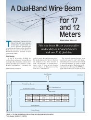
A Low Power 4:1 Current Balun Kitby Charles Greene, <strong>W1CG</strong>w1cg@qsl.netOver the last two years I have build, designed, tested and built many <strong>balun</strong>s-- and have had lots of fun doing it! The perfect, tiny, low loss <strong>balun</strong> stilleludes me, however, but I keep on trying. One of earliest <strong>balun</strong>s I built justhappened to have good performance. So I investigated its design features,improved its performance, rebuilt it using readily available materials, extensivelytested it and I am presenting it here as a construction project for allhomebrewers to enjoy.INTRODUCTIONThe open wire balanced transmission lineis widely used on wire antennas in an attemptto reduce losses and unwanted radiationfrom the transmission line and as a smalllightweight alternative to coax for portableuse. It benefits from a <strong>balun</strong> (BALanced toUNbalanced device) to convert the unbalancedoutput from an antenna tuner to thebalanced input of the transmission line. Theoperator who wants a small, lightweight <strong>balun</strong>for back packing or fix station use for lowpower or QRP operation doesn’t have muchchoice. Either he buys a large, heavy commercial<strong>balun</strong> or else searches the Internetfor the design of a home brew <strong>balun</strong>, theperformance of which is unknown. To helpfill this void, this project concerns a small,low power 4:1 current <strong>balun</strong> that is easy tobuild and has good performance from 160through 10 meters. A 4:1 <strong>balun</strong> is a goodmatch for feeding an Off-Center-Fed antennaand performs well feeding an open wire transmissionline, so that is the type presented.BACKGROUNDThere are essentially two types of coiledtransmission line <strong>balun</strong>s using ferrite or powerediron cores. The first one was introducedby Guanella in 1944 and is known as the“current” <strong>balun</strong>. This <strong>balun</strong> consists of twocoiled transmission lines with the inputs connectedin parallel and the outputs in series.The impedance ratio is 1:N^2 where N is thenumber of wires making up the transmissionline. Two wires have an impedance ratio offour times and three wires an impedance ratioof nine times, for example. Guanella alsoshowed that when the transmission line iscoiled on a magnetic toroidal core or rod it isbroader band than the uncoiled <strong>balun</strong>, andthe length of the transmission line is less. Asthere are balanced currents in the transmissionline, the net flux in the core is zero, sohigh efficiencies can be achieved. (Ref 1, Chap1). A schematic of a 4:1 current <strong>balun</strong> isshown in Figure 1A.In 1957, Ruthroff (Ref 1, Chap 1) usedthe property that a potential gradient existsalong the length of a single transmission lineto introduce the “voltage” <strong>balun</strong>. By connectingthe wires so that the direct voltageadds to the delayed voltage, a 1 to 4 voltageratio is achieved. A schematic of a 4:1 voltage<strong>balun</strong> is shown in Figure 1B. The yearsfollowing the introduction of the voltage<strong>balun</strong> saw its increasing use over the morecomplex current <strong>balun</strong>. It is only recentlythat there is resurgence in use of the current<strong>balun</strong> due to its inherent advantages.There are two problems with the voltage<strong>balun</strong> that limit its usefulness. Because itsprinciple of operation depends on a phaseshift in the voltage along a transmission line,the phase shift becomes inadequate to sustainthe voltage ratio as the frequency increases.The second disadvantage is a resultof the first. In an attempt to extend the highfrequency range, fewer turns are used untilthere is barely adequate inductance for sufficientchoking action to limit the primary currentat the lowest frequency. Working intohigher impedance makes matters worse asthe choking impedance does not change andit becomes a smaller percentage of the totalimpedance. This causes too much of thewrong current to flow which decreases the2 <strong>W1CG</strong> Low Power Balun Kitcurrent to the load and increases losses.The current <strong>balun</strong> operates on the principleof summing the voltages in each of fourcoils, and eddy currents in the windings limitits highest frequency. Therefore, more turnscan be added until eddy currents start to limitoperation at the highest frequency. The additionalturns significantly increase chokingaction at the lower frequencies, and the effectivenessof the <strong>balun</strong> does not decrease asrapidly as that of the voltage <strong>balun</strong> when(B)Figure 1. Two types of coiled transmission line 4:1 <strong>balun</strong>s using ferrite or powerediron cores: (A) The Guanella or Current <strong>balun</strong>; a two core <strong>balun</strong> like the onedescribed in the text is shown. (B) The Ruthroff or Voltage <strong>balun</strong>.working into a high impedance load. Forexample, the <strong>balun</strong> described in this articlehas a SWR of less than 1.08:1 into a noninductiveload of 200 ohms from 700 KHzto 30 MHz. I tested a single core of this twocore current <strong>balun</strong> with the coils connectedas a voltage <strong>balun</strong> (shown in Picture 1) andchecked its frequency coverage. The lowfrequency performance of the voltage andcurrent <strong>balun</strong>s is similar, but the performanceof the voltage <strong>balun</strong> starts to fall off above19 MHz. It has a SWR into a 200 ohm non-<strong>W1CG</strong> Low Power Balun Kit 3
Picture 1. A single core of the two core current <strong>balun</strong>with the coils connected as a voltage <strong>balun</strong>.inductive load of 1.2:1 and higher above 19MHz. In addition, Lewellen reported thathis tests showed that the current <strong>balun</strong> hasimproved performance over the voltage <strong>balun</strong>under all conditions. (See Reference 4.)A PRACTICAL DESIGNSome design guidelines are set forth inthe current literature (Ref 1, 2) for buildinghigh performance <strong>balun</strong>s. I will avoid the mathand the theory and just use some approximationsas practical guidelines. As can beseen from Figure 1A, when working into abalanced load, each pair of windings sees halfthe load Zl: 100 ohms for a 50 to 200 ohm4:1 <strong>balun</strong>. For best matching and power transfer,the Zo of the coiled transmission lineshould equal the load, 100 ohms. The formulafor transmission lines can be used todetermine the wire size for close spaced wire.(I have found that the impedance of the transmissionline wound on a toroidal core is approximately80% of that in air). Close spaced#24 or #26 enamel insulated wire will producethe desired impedance, and can be usedin a low power <strong>balun</strong> without danger of insulationbreakdown. Actually some of the ferritematerial toroidal cores are enamel insulatedwhich increases the voltage breakdownsafety factor.A second guideline is that the minimumimpedance of the inductance of the coilformed by the wound transmission line onthe toroidal core Zo should be ten times theimpedance of the input transmission line Ziat the lowest frequency to choke off the primarycurrent. For the 50 to 200-ohm <strong>balun</strong>,Zo should be 500 ohms at the lowest frequency.The inductance to produce this impedanceat 1.8 MHz is 44 uh.Now we will pick a size. For ease in constructionand for a small <strong>balun</strong> for portableuse, we will pick a size of about 1-inch. Inorder to get sufficient inductance (44 uh) wewill need a material with a mid range permeability.We can not use low loss powerediron material with permeability in the rangeof 1 to 75 because we cannot get enoughturns of #24 or #26 enamel insulated wire ona 1-inch core for an inductance of 44 uh. Aferrite core of type 43 has an initial permeabilityof 850 and reasonable efficiency, andit is enamel insulated for a greater voltagebreakdown safety factor. Using the formulasin the Amidon data book (Ref 3), we findthat 15 turns bifilar wound which will easilyfit on an FT114-43 core will produce an inductanceof 136 uh. This is higher inductancethan required but it will improve theperformance of the <strong>balun</strong> when the load ishigher than 200 ohms. The question is whatthe high frequency limit is.The only way I know to determine thehigh frequency performance for sure is tobuild the <strong>balun</strong> and measure it. The high frequencyperformance of the 15-turn <strong>balun</strong>started to fall off at 10 meters (SWR startedto increase into a non-inductive 200-ohm4 <strong>W1CG</strong> Low Power Balun Kitload), but the SWR was low down to 500KHz, which is well below the desired frequency.This indicates that the design shouldhave fewer turns. So the next <strong>balun</strong> of thedesign had 13 turns. The 13-turn <strong>balun</strong> hasan inductance of 101 uh and its SWR is lowand is flat from 700 KHz to 30 MHz.The wire size can be either #24 or #26enamel insulated wire. I constructed a <strong>balun</strong>of each, and their performances are essentiallythe same. The #24 wire is easier towork with and has slightly less wire loss, sothat is what we will use. To verify the wiresize to give 100 ohms for Zb, I wound a<strong>balun</strong> using #22 wire and measured its performancewhich was a little less than that ofthe other two. It had a somewhat higherSWR with a 200-ohm load. I also found theParts Listo 2 Ferrite toroidal cores, FT114-43o 6-ft #24 NYSOL magnet wireo 6 4” nylon cable tieso 1-ft 3/64” heat shrink tubingTools• Vise (recommended)• Large soldering iron or solder pot for insulationstripping• Heat gun• Common shop tools, including wire cutters,needle nose pliers, utility knife, and anohmmeter.• Optional: Antenna SWR analyzer and a200 ohm 1/2 watt non-inductive resistor.Construction Steps1) Cut the wire into four 18” lengths. Cutthirty approximately 1/8” lengths and two¾” lengths from the heat shrink tubing.2) Lead a cable tie around the core and oneend of the wire pair about 3” from the endand tighten it. See Picture 2.3) Clamp the core in the vise. Some peoplewind toroidal cores without a vise but holdingthe core in a vise allows one to use bothhands. Use a cloth on the jaws of the vise toCONSTRUCTION#22 wire harder to work with than the #24wire, and any improvement in wire losswould be slight. However, I resolved to checkthe loss of all three <strong>balun</strong>s during loss measurements,and use that as one of the criteriain selecting the wire size for the <strong>balun</strong> ofdesign.It is possible to construct a 4:1 current<strong>balun</strong> by winding both pairs of windings ona single core. However, in my experience,the performance of the single core 4:1 current<strong>balun</strong> is not as good as the two-corecurrent <strong>balun</strong>. The SWR is high and is notflat across the HF spectrum. Therefore, this<strong>balun</strong> is wound on two FT114-43 cores (Figure1A). Now that we have a preliminarydesign, we need to describe how to wind itand then test its performance.prevent marring the surface of the core. Leadthe long end of the wire pair through the holeand without twisting the wires pull themaway from the core and cut them to the samelength.4) This is the first turn. Each time the wirepasses through the center is counted as oneturn. Place a 1/8” length of heat shrink tubingover the wire pair where it passes aroundthe outside of the core to hold the wiresclosely together. Do not twist the wire, however,if the wire is inadvertently twisted itwill not affect performance. See Picture 3.5) Continue winding 6 turns spacing eachpair about ¼” on the outside. Pull the wirestight and form them over the edges of thecore with your fingers. Use a 1/8” length ofheat shrink tubing every time the wire paircrosses the outside of the core and heat shrinkit. At the completion of 6 turns, adjust thewire spacing until the sixth turn is 180 degreesfrom the starting point.6) For the seventh turn, lead the wire throughthe inside of the core back to the startingpoint. Place the ¾” length of tubing on thewire pair where passes through the center ofcore and heat shrink it in place. Start windingback around the unused portion of the core.<strong>W1CG</strong> Low Power Balun Kit 5
Picture 2: Lead a cable tiearound the core andone end of the wirepair about 3” from theend and tighten it.Picture 5: One completedcore.Picture 3: Balun corein vise showingheat shrink tubingon outsideof windings.Picture 6: Completedtwo-core 4:1<strong>balun</strong>.Picture 4: Balun corewith six turnsshowing crossoveron the seventhturn.Picture 7: 14 turn versionof <strong>balun</strong> inwatertight enclosurefor installationat top of OffCenter Fed antenna.(Full resolution color images available online at http://www.njqrp.org/qhbextra/8/a)6 <strong>W1CG</strong> Low Power Balun Kit(Full resolution color images available online at http://www.njqrp.org/qhbextra/8/a)<strong>W1CG</strong> Low Power Balun Kit 7
See Picture 4. Continue winding six more,equally spaced turns and adding a 1/8” ofheat shrink tubing on the outside of the corefor each turn. (Note: Reisert, W1JR, usedthis winding technique with the “crossover”in his 1:1 <strong>balun</strong>. Ref 2. The purpose of the“crossover” is to facilitate connection of theinput wires on one side of the <strong>balun</strong> and theoutput wires on the other side. It has noelectrical significance.)7) When done winding, the final turn shouldbe about 180 degrees from the starting point.There should be six turns on each side countingevery time the wire passes through thecenter as one turn. The crossover throughthe center counts as an additional turn butnot one of the six on each side. Using a cabletie clamp the wires loosely to the core. Adjustthe spacing evenly until the two cableties are 180 degrees from each other thentighten the cable tie. Cut the finish ends ofthe wire to the desired length.8) Strip a part of the insulation from about¼” on the end of each of the wires. Place thelarge soldering iron in the vise with the bevelof the tip horizontal and form a blob of solderon the tip. Thermaleze and Nysol wirewill strip in this blob of solder, but it helpsto have a bit of bare wire to better conductthe heat to start the stripping process. Insertthe end of the wire to be stripped into theblob of solder and move it slowly throughthe blob. Add more solder to tin the strippedwire. You can also use a solder pot if youhave one.9) Place one of the 1/8” pieces of heat shrinktubing over one of the wires at the start endand shrink it. Using the ohmmeter, identifythe other end of this wire and shrink a 1/8”piece of tubing on it too. Now you haveidentified both ends of one wire, which wewill use later to hook up to the second core.This completes one core. It should look likethe one in Picture 5.10) Wind the second core and mark the wiresidentically to the first.11) Temporally connect the two cores as follows:On the input side, connect the twomarked wires together and the two unmarkedwires together. The 50-ohm input connectsto these two wire pairs. On the output sideconnect one marked wire to one unmarkedwire.The 200-ohm output goes to the twounconnected wires. Measure <strong>balun</strong> SWR usingan antenna analyzer with a 200-ohm noninductiveresistor connected to the 200-ohmside and the antenna analyzer 50-ohm outputconnected to the input side. If you can’tget the use of an antenna analyzer, connectthe <strong>balun</strong> to your transceiver through an SWRmeter, and reduce the power to the minimumand turn the rig on for a short time to get anSWR reading without burning up the 200-ohm resistor. The SWR should be in the rangeof 1.1:1. If not, check your connections.8 <strong>W1CG</strong> Low Power Balun Kit12) Now you can secure the two cores togetherusing the two remaining cable ties andsolder the wires. It’s a good idea to first inserta piece of paper between the cores witha hole in the center for the cable ties. Alternatively,you can cement the two cores togetherusing silicon seal. It’s not necessary to useQ-Dope to hold the wires in place. The Q-Dope reduces the Q somewhat and makesrepair difficult. You can now attach connectorsto each end or place the <strong>balun</strong> in anenclosure of your choice. The completed<strong>balun</strong> is shown in Picture 6. Picture 7 showsa 14 turn version of the <strong>balun</strong> mounted in awatertight enclosure with a strain insulatorfor mounting at the top of an Off Center Fedantenna.Tests consisted of measuring the inductanceof the windings, SWR tests, loss testsand on-the-air tests using antennas with balancedfeed lines with high SWRs. The mostinteresting tests were the efficiency tests.The efficiency tests consisted of measuringthe temperature rise of the <strong>balun</strong> in a vacuuminsulated thermos container with both a reactiveand a non-reactive load and comparingit to the temperature rise of a resistor. Shortlengths of RG-174 coax and a miniature 200-ohm transmission line served as the input/output leads passing through the top of thecontainer to the device inside. A thermocouplewith its own connecting wires leadingto a meter was used to measure the temperature.The source of RF power was a TenTec Triton IV transceiver which can producepower from zero to 100 watts. A RF Power/SWR meter was used to measure outputpower output of the transceiver, and an antennatuner was used to tune the output ofthe transceiver during high SWR tests. Theoutput of the <strong>balun</strong> under test was connectedto a calibrated dummy load through the impedancematching device. Figure 2 is a blockdiagram and Picture 8 is a photograph of thetest setup, showing most of the equipmentused.For the non-reactive efficiency test, the200-ohm output of the <strong>balun</strong> was connectedto the 200-ohm side of a large commercial4:1 <strong>balun</strong>. The 50-ohm side of the large <strong>balun</strong>was connected to the 50-ohm calibrateddummy load. Fifty watts was applied for aperiod of 10 minutes then reduced to zerofor 10 minutes to avoid overheating the transceiverfinals, then back on for 10 minutes.The temperature was allowed to stabilizefor 10 minutes then measured. Then a 12-watt 50-ohm non-inductive resistor wasTESTINGplaced in the insulated container and lowpower applied with the same power on-offcycle and its temperature rise measured. Iran the test of the resistor several times withdifferent power levels until the temperaturerise of the resistor matched the temperaturerise of the <strong>balun</strong>-under-test. Then power tothe 12-watt resistor is the same as the powerloss of the <strong>balun</strong>-under-test. Efficiency is100% X power-loss / power-applied.For the reactive load tests, the large <strong>balun</strong>was replaced with a Johnson KW Matchbox.The 200-ohm output of the <strong>balun</strong>-under-testwas connected to the balanced outputside of the Matchbox and the Matchbox50-ohm input was connected to the calibrateddummy load. The Matchbox matching andtuning controls were adjusted for as high animpedance as could be read on the AutecVA1 antenna (715 ohms) on the balancedwire side of the Matchbox. In other words,the Matchbox was used in reverse. Powerwas applied in a similar manner to the nonreactiveload tests and the temperature risewas compared to the temperature rise of the12-watt resistor as in the non-inductive tests.Results of the efficiency tests are shown inTable 2.The tests were fairly repeatable in thatseveral runs of the same power gave temperaturerise results within a few percent.The heat loss was very low and temperaturereadout accuracy was very good and its precisionwas 0.1 degree-F. The heat rise methodis independent of all other losses in the system.The limiting factor is ability to read thepower level accurately and hold it for therequired time. The calibrated dummy load/wattmeter has a readout precision of twodecimal points, but it could not be used exceptto check the accuracy of the other wattmeterswhen applying power to the <strong>balun</strong>and the 12-watt resistor.The temperature rise of the <strong>balun</strong> in air isinsignificant during normal operation and ishard to detect without a temperature-measuringinstrument. The temperature rise ofthe <strong>balun</strong> in air using 100 watts CW for 10<strong>W1CG</strong> Low Power Balun Kit 9
Figure 2: Block diagram of test setup.Picture 8: Test setup showing some of the equipment used.minutes with a 200-ohm non-inductive loadwas 7 degrees-F at 7.1 MHz and 15 degreesF at 28 MHz. With the 715 ohm reactiveload used for the above efficiency tests thetemperature rise in air was 16 degrees-F at7.1 MHz.The losses include I^2R and eddy currentlosses but are predominately dielectric andincrease as the voltage gradient across thewindings increase. The best efficiency isattained when the load impedance is 200-ohms. If the impedance load is extremelylow, I^2R losses increase, decreasing efficiencyagain. As shown in table 1, the efficiencywhen operating into a non-reactive200-ohm load is 97%. The loss is 3% or0.12 dB. A loss of 0.12 decibels is insignificantcompared to other losses in an antennasystem, however, at 1000 watts 30 wattswould be dissipated in the <strong>balun</strong> which issufficient to burn up all but the larger <strong>balun</strong>s.The efficiency of the <strong>balun</strong> operated into the714-ohm reactive load is 94%.OPERATIONI have operated the <strong>balun</strong> at 100 wattsCW and SSB with my W3EDP and G5RVantennas that have high impedances on somebands with barely perceptible heating. For alimit, the wire and heat shrink tubing are specifiedfor a maximum temperature of 130 degreesC, and the Curie temperature (the temperatureat which the ferrite material losesmagnetic properties) is also 130 degrees C.For a rule of thumb, don’t operate the <strong>balun</strong>if it is too hot to touch. The voltage breakdownspecification of the wire or core insulationof 500 volts will be exceeded if theimpedance exceeds 2500 ohms. (There is avoltage breakdown safety factor of two inthe design but this is for the situation wherethere is a scratch in the insulation). By allmeans avoid the current node of an openwire transmission line at any power as theimpedance can reach several thousand ohmsat this point, an impossible condition forany <strong>balun</strong>. As a suggestion, operate the <strong>balun</strong>for a few minutes then check its temperature.If the <strong>balun</strong> is hot to the touch, reducepower or move the <strong>balun</strong> to a lower impedancepoint on your transmission line.SUMMARYHere is low power <strong>balun</strong> that everyonecan build that gives reasonable performanceover a wide impedance range for the entireHF band, 160 to 10 meters. The efficiencyof the <strong>balun</strong> is less when operated into a highimpedance reactive load and at higher frequencies,as was expected. The efficiency ofthe <strong>balun</strong> can be improved by using a lowerpermeability, less lossy core material, butthe size of the core would need to be increasedto achieve the desired inductance.This larger <strong>balun</strong> would be able to operate ata higher power level, and would no longer bea small, portable, low power <strong>balun</strong>.REFERENCES1. Sevick, J., “Transmission Line Transformers,”Nobel Publishing Corporation, Atlanta,GA, Fourth Edition, 2001.2. Sevick, J., “Building and Using Balunsand Ununs,” CQ Communications, Inc.,Hicksville, NY, 1994.3. Amidon Associates, (no title data book),Costa Mesa, CA, Jan., 2000.4. Lewellen, J., “Baluns: What They Do andHow They Do It,” The ARRL AntennaCompendium, Vol. 1, American Radio RelayLeague, Newington, CT, 1985, p 157-164.CONTACTING US1) Please be sure to check the online webpages for this project at the NJQRPwebsite at www.njqrp.org/<strong>balun</strong>. We oftenpost additional information about thekits, construction feedback from users, errata,application notes, et.2) For technical questions, please contactthe designer at:Charles Greene, <strong>W1CG</strong>115 Aaron AvenueBristol, RI 028093) Any other questions concerning thiskit may be directed to the NJQRPClub:Dave Porter, AA3UR647 Middle Holland RoadHolland, PA 18966email: aa3ur@comcast.net10 <strong>W1CG</strong> Low Power Balun Kit<strong>W1CG</strong> Low Power Balun Kit 11
12 <strong>W1CG</strong> Low Power Balun Kit