HomeWorks Technical Reference Guide International Edition - Lutron
HomeWorks Technical Reference Guide International Edition - Lutron
HomeWorks Technical Reference Guide International Edition - Lutron
- No tags were found...

Create successful ePaper yourself
Turn your PDF publications into a flip-book with our unique Google optimized e-Paper software.
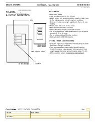
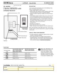
Wallbox Closure InterfaceWallbox20mm (15/16 inch)AddressnumberSwitchsettingsAddressnumberSwitchsettingsKeypad link wiringHWI-WCIThird party low-voltagecontact closure switchFigure 1 – mounting diagramThird party low-voltagecontact closure switchCommonInput 1Wiring for input 1 shown. Wiring istypical of all seven inputs.Set DIP switches 1-5 to give the Wallbox Closure Interface a unique<strong>HomeWorks</strong>® system address from 1 to 32.Example: setting switch 1 on.Up (On)Down (Off)HWI-WCI59.8mm (2.35 inch)DiameterFigure 2 – Contact Closure Input wiring diagramON1 2 3 4 5 6 7 8 9 10Power LEDDIP switches 1-5 for setting address. DIP switches 6-10 do not affectWallbox Closure Interface address.Figure 3 – addressingCOMPONENTSHWI-WCIHWI-WCI1 2 3 4 1 2 3 4<strong>HomeWorks</strong> keypadWallbox ClosureInterfaces can beconnected to anylink configured asan <strong>HomeWorks</strong>Keypad Link.<strong>HomeWorks</strong>® processorPins 1 and 2 – 1 pair 1.0mm 2 (18 AWG) for powerPins 3 and 4 – 1 pair 0.5-1.0mm 2 (22-18 AWG) twisted/shielded for dataEach HWI-WCI counts as seven LEDs toward the capacity of the powersupply for the link.Figure 4 – wiring diagram<strong>Technical</strong> Support: hwisupport@lutron.com7.23