HomeWorks Technical Reference Guide International Edition - Lutron
HomeWorks Technical Reference Guide International Edition - Lutron
HomeWorks Technical Reference Guide International Edition - Lutron
- No tags were found...

Create successful ePaper yourself
Turn your PDF publications into a flip-book with our unique Google optimized e-Paper software.
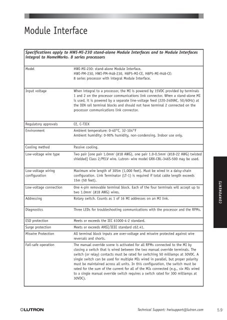
Module InterfaceSpecifications apply to HWI-MI-230 stand-alone Module Interfaces and to Module Interfacesintegral to <strong>HomeWorks</strong> ® 8 series processorsModelHWI-MI-230: stand-alone Module Interface.HWI-PM-230, HWI-PM-H48-230, H8P5-MI-CE, H8P5-MI-H48-CE:8 series processor with integral Module Interface.Input voltageWhen integral to a processor, the MI is powered by 15VDC provided by terminals1 and 2 on the processor communications link connector. When a stand-alone MIis used, it is powered by a separate line-voltage feed (220-240VAC, 50/60Hz) atthe DIN rail terminal blocks and should not have terminal 2 connected on theprocessor communications link connector.Regulatory approvalsEnvironmentCE, C-TICKAmbient temperature: 0-40°C, 32-104°FAmbient humidity: 0-90% humidity, non-condensing. Indoor use only.Cooling methodPassive cooling.Low-voltage wire type Two pair [one pair 1.0mm 2 (#18 AWG), one pair 1.0-0.5mm 2 (#18-22 AWG) twistedshielded] Class 2/PELV wire. <strong>Lutron</strong>® wire model GRX-CBL-346S-500 may be used.Low-voltage wiringconfigurationLow-voltage connectionAddressingMaximum wire length of 305m (1,000 feet). Must be wired in a daisy-chainconfiguration. Link Terminator (LT-1) is required if total cable length exceeds15m (50 feet).One 4-pin removable terminal block. Each of the four terminals will accept up totwo 1.0mm 2(#18 AWG) wires.Rotary switch. Counts as 1 of 16 MI addresses on an MI link.COMPONENTSDiagnosticsThree LEDs for troubleshooting communications with the processor and the RPMs.ESD protectionSurge protectionMiswire ProtectionFail-safe operationMeets or exceeds the IEC 61000-4-2 standard.Meets or exceeds ANSI/IEEE standard c62.41.All terminal block inputs are over-voltage and miswire protected against wirereversals and shorts.The manual override scene is activated for all RPMs connected to the MI byclosing a switch that is wired between the two manual override terminals. Theswitch (or relay) contacts must be rated for switching 50 milliamps at 30VDC. Asingle switch can be used for multiple MIs wired in parallel, but proper polaritymust be maintained across all units. In this configuration, the switch must berated for the sum of the current for all of the MIs connected (e.g., six MIs wiredto a single manual override switch requires a switch rated for 300 milliamps at30VDC).<strong>Technical</strong> Support: hwisupport@lutron.com5.9