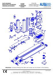
Use and maintenance instructions - Autec-VLT Automotive Equipment
Use and maintenance instructions - Autec-VLT Automotive Equipment
Use and maintenance instructions - Autec-VLT Automotive Equipment
- No tags were found...

Create successful ePaper yourself
Turn your PDF publications into a flip-book with our unique Google optimized e-Paper software.
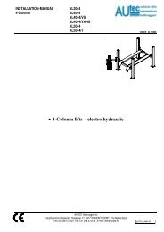
Wheel balancerwith microprocessorfor cars, light commercialvehicles <strong>and</strong> motorcyclesS 820Ed. 09/12 Cod. 3036619<strong>Use</strong> <strong>and</strong> <strong>maintenance</strong> <strong>instructions</strong>Original Instrictions
INDEXIntroduction 61.0 Foreword 71.1 General 71.2 Scopo del manuale 71.3 Where And How To Keep The Manual 81.4 Manual Upgrades 81.5 Collaboration With <strong>Use</strong>rs 81.6 Manufacturer’s Responsibility And Warranty 81.6.1 Terms Of Warranty 91.7 Technical Assistance Service 91.8 Copyright 92.0 Safety rules 102.1 General notes 102.2 Symbols 102.3 Definitions of “operator” <strong>and</strong> “specialised technician” 102.4 Personal protection devices (ppd) 112.5 Protection devices to wear 112.6 General warnings 122.7 Emergencies 122.7.1 First aid 122.7.2 Fire-fighting measures 132.7.3 Airborne noise emission 132.7.4 Operator working position 133.0 Unpacking <strong>and</strong> positioning 133.1 Visual inspection 133.2 Checking the machine <strong>and</strong> equipment supplied 133.3 Unpacking 143.4 Packing list 143.5 Storage 143.6 H<strong>and</strong>ling 153.7 Removing the pallet 153.8 Positioning 163.8.1 Warnings for positioning 164.0 Installation 174.1 Cleaning 174.2 Ambient characteristics 174.3 Fitting the adapters 174.4 Electrical connection 184.4.1 Safety rules 184.4.2 Pneumatic connection 185.0 Residual risks 196.0 Machine Description 206.1 Purpose 206.2 Technical Specifications 216.3 Dimensions 214
7.0 Starting 218.0 Control Panel 249.0 <strong>Use</strong> Of The Wheel Balancer 259.1 Presetting Of Wheel Dimensions 259.1.1 Et (This Function Is Available Only In The Absence Of The La Sonar) 269.1.2 Modifying Set Dimensions 279.1.3 Automatic Width (Option) 279.2 Measurement Result 289.3 Static Unbalance 289.4 Exact Positioning Of The Adhesive Weight By Means Of The Gauge With Clips 289.5 Split Function (Unbalance Resolution) 299.6 Double Operator Program 309.7 Automatic Minimization Of Static Unbalance 3110.0 Setup 3210.1 Menu 3210.2 Unbalance Optimisation 3310.3 Opposite Position 3410.4 Self-Diagnostics 3410.5 Calibration 3510.6 Automatic Gauges Calibration 3610.6.1 Rim Distance Gauge 3610.6.2 Diameter Gauge 3710.6.3 Width Sonar (Option) 3811.0 Diagnostics 3911.1 Inconsistent Unbalance Readings 3911.2 Alarm Signal 3912.0 Maintenance 4212.1 General 4212.1.1 Introductory Notes 4212.1.2 Safety Rules 4212.1.3 Replacing Fuses 4213.0 Disposal 4313.1 Disposing Of The Balancer 4313.2 Disposing Of Electronics Components 4314.0 Spare Parts 4314.1 Identification And Ordering Method 4315.0 Attached Documentation 435
INTRODUCTIONWe thank you for purchasing one product included in our range of wheel-balancers.The machine is manufactured exploiting the best of quality principles.To ensure correct operation <strong>and</strong> long life of the machine, all you need to do is follow these simple <strong>instructions</strong>, whichshall be read <strong>and</strong> fully understood in every single part.DETAILS OF THE wheel-balancersWhen contacting our Service Department or when requesting spare parts, please provide a complete description of theModel of the tyre changer <strong>and</strong> its Serial Number.For the sake of simplicity <strong>and</strong> commodity, the details of your tyre changer are written in the space below.If the details given in this manual do not match those written on the nameplate of your tyre changer, those written onthe nameplate are the ones to be considered valid.DETAILS OF THE MANUFACTURER:- Consult the Declaration of conformity <strong>and</strong> the data nameplate (fitted on the machine)NAMEPLATE DATAFAC-SIMILEThis manual is an integral part of the machine.Before you use the tyre changer, read the warnings <strong>and</strong> <strong>instructions</strong> given in this manual carefully <strong>and</strong> thoroughly,because they provide important information on safe use <strong>and</strong> <strong>maintenance</strong>.Keep this manual with care for future consultationNOTE: some of the illustrations shown in this manual have been taken from pictures of prototypes.Consequently, some parts or components of the machines of st<strong>and</strong>ard production may differ from what is illustrated.6
1.0 ForewordWARNINGThis manual is an integral part of the INSTALLATION manualwhich should be consulted concerning starting <strong>and</strong> using themachine safely. Read carefully before continuing.1.1 GeneralThe machine has been constructed in conformity with the current EC Directives <strong>and</strong> the technical st<strong>and</strong>ardsimplementing the requirements, as stated in the declaration of conformity issued by the manufacturer <strong>and</strong>attached to the manual.This publication, hereinafter simply referred to as ‘manual’, contains all the information required to safely use<strong>and</strong> service the machine referred to in the Declaration of Conformity.This appliance, hereinafter is generically referred to as ‘machine’.The manual addresses operators instructed on the precautions to take in relation to the presence of electriccurrent <strong>and</strong> moving devices.This publication is intended for all ‘users’ who as far as within their competence need to <strong>and</strong>/or are obliged togive <strong>instructions</strong> to others or operate on the machine themselves.These persons can be identified as follows:- operators directly involved in transporting, storing, installing, using <strong>and</strong> servicing the machine from when it isput on the market until when it is scrapped;- direct private users.The original Italian text of this publication constitutes the only reference to resolve any interpretationcontroversies related to the translation into the European Community languages.This publication forms an integral part of the machine <strong>and</strong> must therefore be kept for future reference until finaldismantling <strong>and</strong> scrapping of the machine.1.2 Purpose of the manualThis manual, <strong>and</strong> the installation manual, contains the <strong>instructions</strong> required to use the machine safely <strong>and</strong> carryout routine <strong>maintenance</strong> work.Any calibrations, adjustments <strong>and</strong> extraordinary <strong>maintenance</strong> operations are not considered in this documentas they may only be performed by the service engineer who must work on the machine according to thetechnical <strong>and</strong> rated characteristics for which it was built.Though it is fundamental to read this manual, it cannot replace skilled technical staff who must be adequatelytrained beforeh<strong>and</strong>.The foreseen use <strong>and</strong> configurations of the machine are the only ones allowed by the manufacturer; do notattempt to use the machine in a different way.Any other use or configuration must be agreed in advance with the manufacturer in writing <strong>and</strong> in this case anannex will be attached to this manual.For use, the user must also comply with the specific workplace legislation in force in the country where themachine is installed.The manual also refers to laws, directives, etc., that the user must know <strong>and</strong> consult in order to accomplish thegoals that the manual sets out to achieve.7
1.3 Where <strong>and</strong> how to keep the manualThis manual (<strong>and</strong> relative attachments) must be kept in a safe <strong>and</strong> dry place <strong>and</strong> must always be available forconsultation.Make a copy <strong>and</strong> keep it in the archive.When exchanging information with the manufacturer or the technical assistance staff authorised by the former,quote the rating plate information <strong>and</strong> the serial number of the machine.This manual must be kept for the entire lifetime of the machine, <strong>and</strong> if necessary (e.g.: damage making allor some of it illegible, etc.) the user must request another copy exclusively from the manufacturer, quoting thepublication code indicated on the cover.1.4 Manual upgradesThis manual is an integral part of the machine <strong>and</strong> reflects the state of the art at the moment it was put on themarket. The publication complies with the directives in force on that date; the manual cannot be consideredinadequate as a result of regulatory updates or modifications to the machine.Any manual upgrades that the manufacturer may see fit to send to users will become an integral part of the manual<strong>and</strong> must be kept together with it.1.5 Collaboration with usersThe manufacturer will be pleased to provide its customers with any further information they may require <strong>and</strong> willconsider proposals for improving this manual in order to more fully satisfy the requirements it was written for.In case of transfer of ownership of the machine, which must always be accompanied by the use <strong>and</strong><strong>maintenance</strong> manual, the original user must inform the manufacturer of the name <strong>and</strong> address of thenew user in order to allow it to send the new user any communications <strong>and</strong>/or updates deemed to beindispensable.This publication is the property of the Manufacturer <strong>and</strong> may not be fully or partly reproduced withoutprior written agreement.1.6 Manufacturer’s responsibility <strong>and</strong> warrantyIn order to make use of the manufacturer’s warranty, the user must scrupulously observe the precautionscontained in the manual, in particular he must:- never exceed the limits of use of the machine;- always constantly <strong>and</strong> carefully clean <strong>and</strong> service the machine;- have the machine used by people of proven capacity <strong>and</strong> attitude, adequately trained for the purpose.The manufacturer declines all direct <strong>and</strong> indirect liability caused by:- use of the machine in a different way from that indicated in this manual- use of the machine by people who have not read <strong>and</strong> fully understood the contents of this manual;- use in breach of specific regulations in force in the country of installation;- modifications made to the machine, software <strong>and</strong> operating logic, unless authorised by the manufacturer inwriting;- unauthorised repairs;- exceptional events.Transfer of the machine to a third party must also include this manual; failure to include the manualautomatically invalidates all the rights of the purchaser, including the terms of warranty, where applicable.If the machine is transferred to a third party in a country with a different language from the one written in thismanual, the original user shall provide a faithful translation of this manual in the language of country in whichthe machine will operate.8
1.6.1 Terms of warrantyThe Manufacturer guarantees the machines it manufacturers against all manufacturing or assembly faults for 12(twelve) months from the date of collection or delivery.The Manufacturer undertakes to replace or repair any part which it deems to be faulty free of charge at its factory,carriage paid.If a Manufacturer’s repairman (or a person authorised by the same) is required to work at the user’s facilities, therelative travel expenses <strong>and</strong> board <strong>and</strong> lodging shall be charged to the user.The free supply of parts under warranty is always subject to the faulty part being inspected by the manufacturer(or a person authorised by the same).The warranty is not extended following repairs or other work done to the machine.The warranty does not cover damage to the machine deriving from:- transport;- neglect;- improper use <strong>and</strong>/or use not in compliance with the <strong>instructions</strong> in the operating manual- incorrect electrical connections.The warranty is invalidated in case of:- repairs made by people who were not authorised by the manufacturer;- modifications that were not authorised by the manufacturer;- use of parts <strong>and</strong>/or equipment that were not supplied or approved by the manufacturer;- removal or alteration of the machine identification plate.1.7 Technical assistance serviceFor any technical service operation, contact the manufacturer directly or an authorised dealer always quoting themodel, the version <strong>and</strong> the serial number of the machine.1.8 CopyrightThe information contained in this manual may not be disclosed to third parties. Partial or total duplication,unless authorised by the Manufacturer in writing, through photocopying, duplication or other systems, includingelectronic acquisition, is breach of copyright <strong>and</strong> can lead to prosecution.9
2.0 Safety rules2.1 General notesWarningBefore performing any operation on the machine, carefully read through the entiremanual,paying particular attention to this chapter.The machine has been designed <strong>and</strong> constructed in observance of the CE requirements taking into account normal<strong>and</strong> reasonably foreseeable use.The machine has been constructed for the application stated in the user manual attached hereto.It is not permitted for any reason whatsoever to use the machine for purposes different from those for which it wasdesigned nor to use it in ways different from those described in this manual.The various operations must be performed according to the criterion <strong>and</strong> the chronology described in this manual.2.2 SymbolsThroughout this manual dangerous operations are highlighted with graphic symbols to draw the reader’s attention.WarningThis warning indicates possible occurrence of an event that may lead to seriousinjury or extensive damage to the machine if adequate precautionarycountermeasures are not taken.2.3 Definitions of “operator” <strong>and</strong> “specialised technician”Any professional person who is to access the machine for operation <strong>and</strong> routine <strong>maintenance</strong> is defined as an“operator”.This means persons who have knowledge of the operating <strong>and</strong> <strong>maintenance</strong> procedures of the machine <strong>and</strong>have the following qualifications:1. training that authorises operation according to the safety st<strong>and</strong>ards in relation to the risks deriving from thepresence of electrical power <strong>and</strong> moving devices <strong>and</strong> the risks related to manual load h<strong>and</strong>ling.2. Trained to use the personal protection devices <strong>and</strong> basic fi rst aid training.The employer must assign a suitable person to operate the machine in accordance with the laws in force, assessinghis or her psycho-physical health, personal education, training <strong>and</strong> experience, as well as knowledge of the st<strong>and</strong>ards,requirements <strong>and</strong> provisions for accident prevention.In addition, the operator assigned based on the above must be specifically trained for use of the machine <strong>and</strong> anyaccessories.Finally, the operator must read through this manual.10
2.4 Personal protection devices (ppd)WarningDuring machine installation <strong>and</strong> use it is strictly prohibited to operate without theprotection devices described In this paragraph.The persons that are to operate on <strong>and</strong>/or work in proximity of the machine may not wear clothes with wide sleeves,laces, belts, bracelets or anything else that may pose a potential risk. Long hair must be tied up to prevent any risk.2.5 Protection devices to wearThe following protection devices must be worn.Insulated safety shoes with rubber sole<strong>and</strong> reinforced tip<strong>Use</strong>: alwaysProtective gloves<strong>Use</strong>: alwaysGoggles<strong>Use</strong>: alwaysWorking clothes<strong>Use</strong>: always11
2.6 General warningsCaution:The machine generates, uses <strong>and</strong> may irradiate energy <strong>and</strong> radio frequency. If notinstalled <strong>and</strong> used in accordance with the <strong>instructions</strong> in this manual, it may causeinterference with radio communications.▪ The machine must be installed, maintained <strong>and</strong> used according to the <strong>instructions</strong> given in this manual <strong>and</strong> accordingto the procedures given from case to case.▪ The employer must train the operators for safe installation, use <strong>and</strong> <strong>maintenance</strong> of the machine.▪ Only specialised <strong>and</strong> specifically trained persons are to be allowed access to the machine for any extraordinary<strong>maintenance</strong> operation.▪ Before operating on the electrical parts of the machine cut the power.▪ For the duration of <strong>maintenance</strong>, “Work in progress” signs must be posted in the department in such a way thatthey are visible from all the access areas.▪ Always operate with due caution <strong>and</strong> wear the personal protection devices (PPD).▪ The machine (<strong>and</strong> any accessory devices) must always be connected to earth to discharge short-circuit currents <strong>and</strong>electrostatic voltages. The mains voltage must correspond to the value shown on the machine identifi cation plate. Itis inadvisable to use cable extensions/socket adaptors. When the machine is not used, disconnect it from the mainsby pulling the plug from the socket.▪ Before carrying out any operation stop the machine.▪ In the event of fire, do not use water but only powder or carbon dioxide fire extinguishers.▪ It is strictly prohibited to deposit combustible material in the vicinity of the machine.▪ Do not deactivate the safety devices or ignore warnings <strong>and</strong> alarms, be they communicated by the software or bywarning labels fixed on the installation. Should the plates, adhesive labels, decals or any other warning sign onthe machine deteriorate they must be replaced.▪ It is not permitted for any reason whatsoever to modify, tamper with or alter the machine structure, the devicesfitted, the operating sequence, etc. without prior consultation with the manufacturer.▪ All the routine <strong>and</strong> extraordinary <strong>maintenance</strong> operations must be recorded in the logbook noting down the date,time, type of operation, name of the operator <strong>and</strong> any other useful information.▪ In the event of faults or malfunctioning, contact your local distributor or the manufacturer. All the repair operationsmust be performed by qualified technicians.▪ It is strictly prohibited to clean the internal <strong>and</strong> external electrical parts of the wheel balancer with water.▪ Exclusively use alcohol to clean the machine. Do not use any other chemical product. Do not under any circumstancesblast with compressed air.▪ Do not leave the machine exposed to the rain or the elements. The ambient storage <strong>and</strong> operating conditions mustmeet the requirements set out in the chapter INSTALLATION.▪ In the event of failure, deformation or malfunctioning of the safety devices, immediately replace them; “Makeshift”repairs are strictly prohibited. <strong>Use</strong> only original spare parts for which the machine has been designed <strong>and</strong> constructed.▪ The machine <strong>and</strong> the workplace must be kept perfectly clean.▪ When the <strong>maintenance</strong> operations have been completed, before restoring the power supply, carefully check thatyou have not forgotten tools <strong>and</strong>/or other materials in the machine operating area. In any event, also during operation,no object may be placed on the protection shield.2.7 Emergencies2.7.1 First aidFor any first aid follow the corporate regulations <strong>and</strong> conventional procedures.12
2.7.2 Fire-fighting measuresDo not use water to extinguish fires, but only powder or carbon dioxide extinguishers. Preferably use extinguishersfilled with a special powder for metal fires.2.7.3 Airborne noise emissionThe machine noise, measured with the machine empty, is constantly contained at levels below 70 dB(A).During operation the machine noise is subordinate to the background noise in the workplace, the presence of othermachines <strong>and</strong> other factors that cannot be assessed by the manufacturer in advance.The user therefore needs to make a phonometric measurement of the noise emitted by the machine during normaloperation, <strong>and</strong> provide for personal protection devices (headsets) if the noise emission exceeds the threshold laiddown in the regulations in force in the country where the machine is used.2.7.4 Operator working positionDuring balancing the operator must st<strong>and</strong> in front of the control console <strong>and</strong> avoid st<strong>and</strong>ing in front of the wheel duringthe balancing cycle.3.0 Unpacking <strong>and</strong> positioning3.1 Visual inspectionThe packaging must be intact upon receipt, i.e.:▪ There must not be any sign of collision or breakage▪ There must not be any sign that it was exposed to sources of heat, ice,water, etc.▪ There must not be any sign of tampering.Any deformations indicate that the machine was knocked about duringtransport <strong>and</strong> may compromise proper machine functioning.3.2 Checking the machine <strong>and</strong> equipment suppliedThe main body of the machine, the relative accessories <strong>and</strong> the equipmentsupplied (as agreed with the manufacturer) must be in perfect condition.The supply is carefully checked before shipment, nevertheless it is advisableto check upon receipt that it is complete <strong>and</strong> in order.Check that:▪ The shipping data (addressee, number of packages, order number, etc.) correspond to the accompanyingdocumentation.▪ The technical-legal documentation provided with the machine includes the instruction manual for the type ofmachine to be installed as well as the EC declaration of conformity or, alternatively, the declaration of themanufacturer.INFORMATIONIn the event of defects <strong>and</strong>/or missing material immediately notify the manufacturer<strong>and</strong> follow his <strong>instructions</strong> before proceeding with installation <strong>and</strong> startup.13
3.3 UnpackingOperate as follows to unpack the machine:1. Cut the plastic safety straps2. Open the top of the cardboard box3. Remove the top protection4. Remove any protective corner pieces5. Remove the cardboard box pulling it upward6. Remove any protective “pluriball”7. Inspect the machine to check for any damage. Immediately inform the carrier <strong>and</strong> the supplier in the event ofapparent damage.Keep the packaging materials for possible future shipment of the machine.INFORMATIONThe packaging used is in compliance with the environmental requirements set out inthe European packaging regulations (Official EC Gazette, N. L. 365/19). Thecardboard boxes can easily be recycled. The plastic wrappings are made ofmaterials free of hazardous metals. It is advisable to contact the competent localauthority for their disposal.3.4 Packing listAll the materials included in the supply are listed on the packing list. The contents may vary from machine to machinedepending on the sales agreements, the optional parts supplied, etc.Generally, the supply includes:▪ the machine▪ the toolbox▪ the instruction manual3.5 StorageWhen the machine:▪ is not immediately installed;▪ is uninstalled <strong>and</strong> stored pending moving to another place position it in a covered place protected against directcontact with atmospheric agents <strong>and</strong> dust.The permitted ambient values in the storage area are as follows:▪ Temperature: +5 to +40°C (41 - 104°F)▪ Relative humidity: 30÷80 %.If taking the machine out of service after a period of use <strong>and</strong> after performing the necessary <strong>maintenance</strong> operations,it can be stored for a period of not more than two years, provided that it is stored in a closed dust-free environmentwithout aggressive agents <strong>and</strong> with the following characteristics:▪ Ambient conditions as described above▪ Positioned in such a way that it is protected against deformation, crushing, breakage, etc.▪ Not subjected to knocks, vibrations, overhanging loads, etc.14
3.6 H<strong>and</strong>lingThe term “h<strong>and</strong>ling” means unloading the machine from the means oftransport <strong>and</strong> positioning it in the place where it will be used. Upon receiptthe customer needs to unload the machine using his own means <strong>and</strong> storeit in a dry <strong>and</strong> protected place pending installation.The machine is to be h<strong>and</strong>led while still fastened on the wooden pallet(see next paragraph) by suitably trained persons wearing the personalprotection devices.WarningH<strong>and</strong>le the machine with extreme care, lifting it the minimum necessary <strong>and</strong> avoidingdangerous oscillation <strong>and</strong> unbalancing.Before moving the machine, it must be tied to the lift truck (or transpallet) to preventit from shifting <strong>and</strong> turning over.Before lifting the machine with a lift truck or transpallet, make sure that the forks are properly positioned <strong>and</strong> protrudefrom the opposite side by at least 30 cm.3.7 Removing the palletThe machine is secured to a base pallet. Prepare an adequate area with level flooring <strong>and</strong> mark it off before liftingthe machine <strong>and</strong> positioning it on the ground.To remove the machine from the pallet operate as follows:▪ Remove the screws that lock the machine to the palletWarningManual h<strong>and</strong>ling <strong>and</strong> lifting of the machine must be carried out with the aid of a lifttruck. Prise on the base near the 3 support points as shown in the figure below.Other points, such as the head or the accessory tray, must not be forced under anycircumstances.15
3.8 Positioning3.8.1 Warnings for positioningThe machine must be positioned respecting the following conditions:▪ The humidity <strong>and</strong> the temperature must be within the prescribed limits▪ The fire-fighting measures must be respected▪ Allow for sufficient space at the front, side <strong>and</strong> rear of the machine for service or periodic <strong>maintenance</strong> <strong>and</strong> at thesame time to assure adequate air circulation. It is advisable to leave a space of about 1 metre around the machine.▪ The place where the machine is installed must be free of corrosive/explosive powders or gas.▪ The place of installation must be vibration-free.▪ The lighting must be such that the various machine functions can clearly be seen.▪ Lift the machine <strong>and</strong> position it correctly in its final position▪ The machine must st<strong>and</strong> on a flat rigid surface <strong>and</strong> possibly away from any joint in the floor.INFORMATIONAccording to UNI EN 10380 regulations, the lighting for a generic working area (suchas control rooms, fixed workstations in production plants, etc.) must on average be300 lux (acceptable values between 200 <strong>and</strong> 500 lux). If the machine is installed in acountry different from Italy, the specific regulations in that country must be followed.The lighting system must be such as to guarantee average lighting of 300 lux for the working environment. This valuedepends on various factors, such as the characteristics of the working environment (more or less reflecting walls <strong>and</strong>ceiling, height of the light points, etc.) <strong>and</strong> the type of bulbs used.16
4.0 InstallationWarningThe <strong>instructions</strong> in this chapter address the operator who must operate wearing thepersonal protection devices indicated in chapter 2.5.4.1 CleaningBefore starting the machine, clean off any dust, foreign matter <strong>and</strong> soiling that may have accumulated duringtransport. <strong>Use</strong> alcohol to clean the plastic parts.Caution:Do not use liquids containing solvents or blasts of compressed air to clean the wheelbalancer.4.2 Ambient characteristicsThe operating environment must have the following characteristics:▪ Temperature: + 5 to + 40°C (41 - 104°F)▪ Maximum relative humidity: 80%The machine may not be used in open places <strong>and</strong>/or exposed to atmospheric agents or in environments with corrosive<strong>and</strong>/or abrasive vapours, fumes or dust with the risk of fire or explosion, <strong>and</strong> in any case where the use ofexplosionproof components is prescribed.Caution:Should at the time of installation the ambient conditions be different from thoseprescribed, or if they have changed over time, do not use the machine but immediatelycontact the manufacturer for the relative inspection.4.3 Fitting the adaptersINFORMATIONBefore fitting the terminal to the wheel balancer, it is advisable to thoroughly clean the machine shaft <strong>and</strong> theadapter hole. Any traces of dirt may affect the balancing accuracy.The wheel balancer is supplied complete with adapter <strong>and</strong> cones for fastening wheels with a central hole.Thethreaded terminal may already be fitted on the machine or be provided in the equipment box; to fit it use an Allenwrench as shown in the drawing. It can be removed to fit optional adapters.17
Caution:Using non-original accessories might compromise the measuring quality. Contact themanufacturer for the supply of special Adapters or spare parts of any kind.4.4 Electrical connection4.4.1 Safety rulesBefore performing any operation, read <strong>and</strong> apply the following:▪ Make sure that the main electric cabinet to which the machine is connected is connected to the earth circuit <strong>and</strong>is adequately protected as required by the regulations in force in the country where the machine is installed.The socket to which the machine is connected must have a slow acting safety switch calibrated to 4 A (230V) or8A (115V).▪ Check that the mains voltage <strong>and</strong> frequency correspond to the values indicated on the machine identifi cationplate.▪ The socket to which the machine is connected must be dimensioned to support the power absorbed up to a maximum of 1.1 kW.The machine is supplied with a single-phase cable to which a plug conform to the regulations must be connected. Ifan extension needs to be used, bear in mind that the wire cross-section may not be less than 2.5 mm2. Make surethat the extension is arranged so that it does not constitute a risk or obstruction.WarningThe connection to the single-phase mains must always be made between phase <strong>and</strong>neutral <strong>and</strong> never between phase <strong>and</strong> earth! It is strictly prohibited to turn on the machineif it is not properly connected to earth according to the technical specifications set outin the regulations in force. In any event, the electrical connections must be carried outexclusively by a specialised technician.4.4.2 Pneumatic connectionIf the machine is equipped with a pneumatic locking/release spindle <strong>and</strong>/or WBL81 lift, it needs to be fed withcompressed air at 8-10 bar. The compressed air coupling is positioned on the rear of the machine. The compressedair must be clean <strong>and</strong> dry. The pipes <strong>and</strong> pipe fittings must be properly connected by appropriately trained personnel.The warranty does not cover damage caused by the absence of an adequate air filtration system.18
5.0 Residual risksResidual risk means a potential risk impossible to eliminate or partially eliminatable, which may cause injury to theoperator if operating using improper working methods <strong>and</strong> practices.▪ Pay attention to the position of your h<strong>and</strong>s in the areas indicated in the figure, asthere is a risk of crushing your fingers during wheel locking on the spindle.▪ While mounting or dismounting the tyre, pay attention to avoid accidentallycrushing your feet.▪ For machines equipped with lift, do not st<strong>and</strong> in the working area, as thereis a risk of crushing during ascent <strong>and</strong> descent of the lift.19
6.0 Machine description6.1 PurposeThe S820 is used to balance the wheels of cars, vans, 4-WD, motorcycles <strong>and</strong> scooters weighing less than 75Kg. It can be operated in the temperature range of 0° to + 45°C.The machine can operate only on flat non resilient floor.To lift the machine, lever only on the base where the 3 support points are located. never, under any circustance,apply force to other points such as the spindle, head, or accessory shelf. It functions properly without having tofasten it to the floor with wheels weighing up to 35 kg; for heavier wheels, fasten it at the points indicated. Do notmount anything other than motorbike, car or truck tyres on the wheel balancer.Thanks to the new <strong>and</strong> exclusive VDD (Virtual Direct Drive) system, reliable unbalance measurements can be made ina short time, almost half the time of the cycle used with respect to other balancers in this range.123451. CONTROL PANEL2. WEIGHT-TOOL HOLDER3. LOCK NUT4. AUTOMATIC GAUGE5. BRAKEThe main features include:▪▪machine settings menu▪▪grams/ounces direct selection▪▪optimisation of tyre <strong>and</strong> rim unbalance▪▪static programme, ALU; SPLIT; double operator; self diagnostics; calibration.▪▪automatic minimisation of static unbalance20
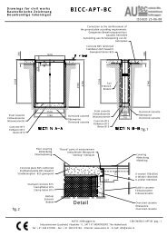
6.2 Technical specificationsThe following data refers to the balancer in its st<strong>and</strong>ard configuration.Single-phase power supply 230 V 50/60 HzProtection class IP 54Max.power consumption 0,65 KwBalancing speed 100 min -1Cycle time for wheel 4.7 sec. (5 3/4”x14”) 15 kg.Measurement uncertainty 0,5 gAverage noise< 70 dB (A)Rim width setting range 1.5” ÷ 20” or 40 ÷ 510 mmDiameter setting range 10” ÷ 30” or 265 ÷ 765 mmMaximum wheel weight < 75 kg.machine weight105 kg.6.3 Dimensions154012801150 135021
7.0 StartingWARNINGBefore switching on the machine, make sure that all the connections describedin the INSTALLATION chapter have been made correctly. The followingoperations involve a potential risk for the operator, given the presence ofvoltage on the equipment. The Personal Protective <strong>Equipment</strong> described in theINSTALLATION manual must be worn <strong>and</strong> work must be done with due care <strong>and</strong>attention. Operations may only be performed by a specialised technician.Before powering the machine, carry out the following checks:1. check that the balancing machine touches the floor at the three support points;2. make sure that all the parts of the balancer are correctly connected <strong>and</strong> fixed;3. make sure that the parameters (voltage <strong>and</strong> frequency) of the mains power supply are compatible with thoseindicated on the rating plate of the balancer;4. make sure the power cable is correctly connected;5. make sure the machine shaft <strong>and</strong> flange hole are clean.CAUTIONAny traces of dirt may affect balancing accuracy.6. To switch on the balancer press the switch on the left-h<strong>and</strong> side of the machine.On - Off22
7. Position the wheel on the terminal with the inner part facing the balancer;8. Firmly attach the wheel to the balancer shaft using the lock nut.9. In the normal version, the pedal controls a mechanical brake which facilitates locking the locking ring <strong>and</strong>positioning the wheel for correction.10. At this point, you can read the tyre measurements <strong>and</strong> perform balancing.23
8.0 Control panel31 2 416131267 718155179 14810 111-2 Digital readouts, AMOUNT OF UNBALANCE, inside/outside3-4 Digital readouts, POSITION OF UNBALANCE, inside/outside5 Inside correction mode selection button6 Indicators, correction mode selected7 Indicators, selection made8 Manual WIDTH/DISTANCE/DIAMETER setting buttons <strong>and</strong> MENU selection9 Push button, FUNCTION MENU10 Balancing cycle stop button11 Balancing cycle start button12 Position repeater push button13 Push button, SPLIT (unbalance resolution)14 MENU selection confirmation pushbutton15 Push button, unbalance reading < 5 g (.25 oz)16 Push button, operator selection17 Grams/ounces selection pushbutton18 Distance gauge position indicationCAUTIONPress the buttons with your fingers.Never use the counterweight grippers or other pointed objects!24
9.0 <strong>Use</strong> of the wheel balancer9.1 Presetting of wheeldimensionsThe balancing data is set by means of an “intelligent” automatic gauge; confirmation of the measurement <strong>and</strong>the position appear on the display. The round part of the gauge must rest on the rim where the weight will bepositioned.Using the special grip, move the end of the gauge against the rim in one of the positions A/B shown inrelation to the kind of repeater set ( TYPE OF REPEATER).▪▪The measurement is the same in position A or B. If the correction type is with adhesive weights on theinside (ALUM), to enable the position repeater function, press the button .abWhile the gauge is moving the following appears:when the measurement has been stored:If the acoustic signal is enabled ( ACOUSTIC SIGNAL), the acquisition of the dimensions is accompanied by a“beep”.a) st<strong>and</strong>ard weights: when only one measurement is made, the machine interprets the presence of a rim with clip-onweight correction25
9.1.1 ET (This function is available only in the absence of the LA sonar)Enabling the ET function, after the end of the automatic distance <strong>and</strong> diameter measurement, the wheel balancersuggests the most likely width value for the dimensions just acquired. If necessary, change the width value bypressing thebuttons, otherwise proceed with normal balancing.CAUTIONThe ET function does not work with the adaptersIf the ET function is disabled, the width value (b) must be set with thebuttons. The correctmeasurement is that which can be measured with the compass gauge provided.bb) adhesive weights: make two successive measurements on two correction planes inside the rim.The balancing machine automatically interprets that the correction will be made with adhesive weights <strong>and</strong> thefollowing appears:For a different combination of the type or position of the weights on the rim, use the button .26
9.1.2 Modifying set dimensionsIf the wheel dimensions have been entered incorrectly, the parameters can be modified without repeating thebalancing spin by pressing for 2 seconds :access parameter modification → (selectto modify: (a) distance, (b) width, (d) diameterIn the case of st<strong>and</strong>ard weights:(a)distance,(b)width,(d)diameterIn the case of adhesive weights:(a1) inside distance,(a2) outside distance,(d1) inside diameter,(d2) outside diameter pressto select (a) (b) or (d)→to recalculate the unbalance or:pull out the gauge to repeat the measurement →to obtain the new measurement.9.1.3 Automatic width (option)At the end of the automatic measurement of the distance <strong>and</strong> diameter the following appears:For large wheels (e.g. off-road vehicles, light trucks or wheels protruding far out from the rim) press theto switch from:N.T. = NORMAL TYREL.T. = LIGHT TRUCKbuttonSlowly close the wheel guard until a “beep” is heard. If “AUTOMATIC START” is enabled when the guard isclosed, the balancing machine performs a cycle to measure the imbalance, otherwise the width value justacquired is shown.Press the buttonto perform a spin.27
9.2 Measurement resultMove the wheel manually until all the LED’s corresponding to the side light up. The display shows themeasured unbalance. If the wheel clamp option is enabled (see MENU), the wheel is automatically clamped inthe correction position. Pressingthe wheel (see MENU).For unbalance within tolerance 0 (zero); usingthe chuck can be locked/released in any position to facilitate mountingvalues within tolerance can be viewed.After positioning <strong>and</strong> locking the wheel, apply the weight vertically at the top.9.3 Static unbalanceIt is selected by pressing <strong>and</strong> is shown on the central display. The position is indicated on the displays 3<strong>and</strong> 4.9.4 Exact positioning of the adhesive weight by means of the gauge with clips▪▪Press if using the correction method with adhesive weights on the inside of the rimFIFE▪▪▪▪▪▪▪▪▪▪▪▪▪▪Fit the correction weight in the specific gauge seat with the adhesive part facing upwardsBring the wheel into correct angular position for the plane to be corrected.Pull the gauge further outwards.Return the gauge to the rest position.When the weight application distance has been reached a beep is sounded (can be deactivated)Rotate the gauge until the correction weight adheres to the rimthe fact that the weight application position is no longer vertical is automatically compensatedINDICATIONThe approach of the weights to the correction positions is indicated by the LEDs number 1828
- Inside correction position- Outside correction positionTo cancel the function, press thebutton again.9.5 SPLIT function (unbalance resolution)The SPLIT function is used to position the adhesive weights behind the wheel spokes (angle > 18°) so that theyare no longer visible (for alloy rims). <strong>Use</strong> this function in the ALU or STATIC mode where the adhesive weight isapplied inside the rim.Enter the wheel dimensions in the ALU M mode <strong>and</strong> press START.a. Turn the wheel to the outer side unbalance correction position.21b. Move one of the spokes to 12 o’clock (e.g.: 1) <strong>and</strong> press2129
c. Following the direction of rotation indicated by the position LED’s, move spoke 2 to12 o’clock <strong>and</strong> pressThe value to use for correction in position 2 is displayed.21d. Move spoke 1 to the correction position as indicated by the position LED’s21INDICATIONIf the OP function is enabled, see the chapter OPPOSITE POSITION for application of theweights at the bottom.To return to the normal unbalance indication press any button.INFORMATIONThe spoke-to-spoke distance must be a minimum of 18° <strong>and</strong> a maximum of 120° (if not, errors24, 25 or 26 appear). Spokes with irregular or inconstant angles can be compensated.9.6 Double operator programThis program allows memorizing the dimensions of two types of wheels. Thus two operators can work simultaneouslyon two differents cars using the same balancing machine. The system memorizes two programs with various presentdimensions.1. Press to select the operator (1 or 2).2. Enter the dimensions (see WHEEL DIMENSIONS PRESETTING)3. Press to carry out the balancing as usual <strong>and</strong> to automatically store the program to the currentlyselected user.Pressto select program 1 or 2 for subsequent balancing operations without setting the dimensions again.30
9.7 Automatic minimization of static unbalanceInitial unbalancesx dxg gPhase shift 50°Possible approximationssxgdxgsxgdxgsx4 g 3 g 1 g static residue 6 gstatic residue static residue static residueWith traditional wheelbalancergdxChoice with minimum staticunbalancegsxgdxgThis program is designed to improve the quality of balancing without any mental effort or loss of time by the operator.In fact by using the normal commercially available weights, with pitch of 5 in every 5 g, <strong>and</strong> by applying the twocounterweights which a conventional wheel balancer rounds to the nearest value, there could be a residual staticunbalance of up to 4 g. The damage of such approximation is emphasized by the fact that static unbalance is cause ofmost of disturbances on the vehicle. This new function, resident in the machine, automatically indicates the optimumentity of the weights to be applied by approximating them in an “intelligent” way according to their position in order tominimize residual static unbalance.31
10.0 Setup10.1 MenùThis is used to personalise some balancer functions <strong>and</strong> to perform calibrations.To access this section, press the FUNCTIONS MENU button.See chapter on unbalance optimisationdiametermm/inchwidthmm/inchstart fromguard closingapproximates1-5g 0.1-25ozon/off beepsignalopposite positionon/offSee AUTO-DIAGNOSTICSSee CALIBRATIONAutomatic widthmeasurementapproximationON/OFFCalibration of automatic RIM DISTANCE gaugeCalibration of automatic DIAMETER gaugeWIDTH calibrationReturn to measurement screenINFORMATION* The ET function is available only in the absence of the LA sonar32
10.2 Unbalance optimisationThis operation is performed to reduce the static unbalance of the wheel.It is suitable for static unbalance values in excess of 30 grams.a. If no unbalance was measured before, START appears on the display. Press this button to proceed.b. Make a reference mark on the flange <strong>and</strong> the rim (using a piece of chalk, for example).With the aid of a tyre remover, turn the tyre on the rim by 180°.Refit the wheel in such a way that the reference marks on the rim <strong>and</strong> the flange coincide.Press START to begin reading.c. RH display: percentage reduction valueLH display: actual static unbalance value which can be reduced by rotationd. Mark the two positions of the rim <strong>and</strong> tyre, <strong>and</strong> turn the tyre on the rim until the positions coincide to achievethe optimisation shown on the displayTYREPOSITIONRIMPOSITIONTo cancel optimisation at any time, press33
10.3 Opposite positionThe normal balancing condition requires the correction weights to be applied at the top (12 o’clock) when the symbolis displayed:If “OPPOSITE POSITION” is enabled, the phase displays also indicate the weight application position at the bottom(6 o’clock) to facilitate cleaning the rim <strong>and</strong> the relative application of adhesive weights. The symbol used is:10.4 Self-diagnosticsThe machine can perform self-diagnostics to check the LED’s on the control panel <strong>and</strong> make sure the encoderreads correctly.To perform this operation, view the SETUP menu.In the self-diagnostics sequence, all the LED’s on the panel light up for a few seconds in order to check operation.When the LED’s go out, the machine automatically moves on to the encoder reading phase. When the wheel is turnedmanually (forwards <strong>and</strong> backwards), the display shows its exact position. The value lies between 0 (zero) <strong>and</strong> 255.34
10.5 CalibrationTo calibrate the machine, proceed as follows:▪▪Fit an average size wheel with a metal rim on the shaft. Example: 6” x 15” (± 1”).▪▪Set the wheel measurements as described in paragraph USE OF THE WHEEL BALANCER.CAUTIONSetting incorrect dimensions would mean that the machine is not correctly calibrated,Therefore, all subsequent measurements will be incorrect until calibration is performedonce again with the correct dimensions.Display the SETUP menu:1. Press to view the CALIBRATION function.2. Add a st<strong>and</strong>ard weight of 60 g (2.00 oz) to the outer side, in any position. Failing a weight of 60g (2.00oz)pressto change the calibration weight from 40 to 100g (1.40 to 3.50oz)3. Shift the st<strong>and</strong>ard weight from the outside to the inside keeping the same position.4. Turn the wheel until the st<strong>and</strong>ard weight is at the top (12 o’clock).5. End of calibration.To cancel calibration at any time, press35
10.6 Automatic gauges calibration10.6.1 Rim distance gaugeDisplay the SETUP menu1. Press to view the rim distance gauge CALIBRATION function.2. Leave the distance gauge in rest position <strong>and</strong> press4. Bring the gauge in line with the adapter flange <strong>and</strong> pressCORRECT CALIBRATION• Return the gauge to rest position.• The wheel balancer is ready for operation.INDICATIONIn the event of errors or faulty operation, the writing “r.P.”: appears on the display : shift thegauge to the rest position <strong>and</strong> repeat the calibration operation exactly as described above. Ifthe error persists, contact the Technical Service Department. In the event of incorrect input inthe rim distance gauge calibration function, pressto cancel it.36
10.6.2 Diameter gaugeDisplay the SETUP menu1. Press to view the diameter gauge CALIBRATION function.2. Place the round part of the gauge terminal on the flange as shown in the figure <strong>and</strong> press3. The number 354 ± 3° appears on the left display .4. Turn the gauge downward position the round part of the gauge terminal at 40 mm (radial distance) from theflange as indicated in the figure; alternati vely use one of the cones provided as shown in the images40 mm5. The number 254 ± 3° should appear on the left display. The calibration is already correct.If not, press thebutton holding the gauge still at 40 mm: the number 254 appears on the left display.Return the gauge to rest position.37
10.6.3 Width sonar (option)Display the SETUP menu1. Press to view the width sonar CALIBRATION function.2. Set with the distance in mm between the Sonar sensor (0 sonar) <strong>and</strong> the end of the distancegauge (at rest).A = Distance: Gauge at rest to 0 sonarIn the event of incorrect input in the width gauge calibration function, pressto cancel it.38
11.0 Diagnostics11.1 Inconsistent unbalance readingsIn some cases, when a wheel that has just been balanced is repositioned on the balancer, the machine can detectan unbalance.This is not a machine problem but is due to faulty mounting of the wheel on the flange. In other words, whenmounting the wheel after initial balancing, it has taken another position with respect to the balancer shaft axis.If the wheel has been mounted on the flange with screws, the screws may not have been tightened correctly(criss-cross sequence) or the tolerances of the holes drilled in the wheel may be too large. Small errors, up to 10grams (0.4 oz), are to be considered normal in wheels locked with the relative cone: The error is normally greaterfor wheels locked with screws or studs.If, after balancing, the wheel is still unbalanced when refitted on the vehicle, this could be due to an unbalancedbrake drum or, very often, the tolerances of the holes drilled in the rim <strong>and</strong> drum are too large. In this case,balancing should be performed using a balancer with the wheel mounted on the vehicle.11.2 Alarm signalThe machine has a self-diagnostics cycle which identifies the most frequent malfunctions during the normal workcycle.These malfunctions are processed by the system <strong>and</strong> shown on the display.39
WARNINGThe information in the POSSIBLE REMEDY column requires work to be performed byspecialist technicians or other authorised people who must always work using thePersonal Protective <strong>Equipment</strong> indicated in the INSTALLATION manual. In some cases,this work can be performed by a normal operator.ERROR CAUSE POSSIBLE REMEDYBlackErr. 1Err. 2Err. 3Err. 4The wheel balancer does notswitch on.No rotation signal.Speed too low duringdetection. During theunbalance measurementrevolutions, the wheel speedhas fallen to below 42 rpm.Unbalance too high.Rotation in oppositedirection.1. Check the machine is properly connected to the mains powersupply.2. Check the fuses on the power board <strong>and</strong> replace if necessary.3. Replace the CPU board.1. <strong>Use</strong> the self-diagnostics function to check the encoder.2. Replace the encoder.3. Replace the CPU board.1. Make sure that a vehicle wheel is mounted on the wheel balancer.2. <strong>Use</strong> the self-diagnostics function to check the encoder.3. Disconnect the piezo connectors from the board <strong>and</strong> do a spin(if no error is detected, replace the piezo sensors).4. Replace the CPU board.1. Check the wheel dimensions setting.2. Check the detection unit connections.3. Run the machine calibration function.4. Mount a wheel with more or less known unbalance (less than100 grams) <strong>and</strong> check the response of the machine.5. Replace the CPU board.1. <strong>Use</strong> the self-diagnostics function to check the encoder.2. Check the encoder bearing/spring.Err. 5Err. 7Err. 8Err. 9Err. 11Err.14Err.15Err.16Err.17Err.18Err. 19Err. 20Guard openThe [START] pushbutton waspressed without first closingthe guard.NOVRAM parameter readerrorToo high speed error.The average spinning speed ismore than 240 rpm.Unbalance measurementerror.Wheel still. The wheel mustremain still for more than onesecond after START.Err. 21 Motor on for more than 15seconds.Err. 22Maximum number of spinspossible for the unbalancemeasurement has beenexceeded.1. Reset the error.2. Close the guard.3. Verify the function of the protection switch.4. Press the [START] button.1. Switch off the machine <strong>and</strong> wait for at least ~ 1 min;re-start the machine <strong>and</strong> check it works properly.2. Repeat machine calibration.3. Replace the CPU board.1. <strong>Use</strong> the self-diagnostics function to check the encoder.2. Replace the computer board.1. <strong>Use</strong> the self-diagnostics function to check the encoder.2. Check the detection unit connections.3. Check the machine earthing connection.4. Mount a wheel with more or less known unbalance (less than100 grams) <strong>and</strong> check the response of the machine.5. Replace the CPU board.1. <strong>Use</strong> the self-diagnostics function to check the encoder.2. Check the connections on the power board.3. Replace the CPU board.1. <strong>Use</strong> the self-diagnostics function to check the encoder.2. Check the connections on the power board.3. Replace the CPU board.1. Check that a vehicle wheel has been mounted on the wheelbalancer.2. <strong>Use</strong> the self-diagnostics function to check the encoder.3. Replace the computer board.40
Err. 24Err. 25Err. 26Distance between the spokesless than 18 degrees.Distance between the spokesgreater than 120 degrees.First spoke too far from theunbalance1. The minimum distance between the spokes where theunbalance is to be split must be greater than 18 degrees.2. Repeat the SPLIT function increasing the distance between the spokes.1. The maximum distance between the spokes where theunbalance is to be split must be less than 120 degrees.2. Repeat the split function increasing the distance between thespokes.1. The maximum distance between the unbalance position <strong>and</strong>the spoke must be less than 120 degrees.2. Repeat the split function increasing the distance between thespokes <strong>and</strong> the unbalance.41
12.0 Maintenance12.1 GeneralCAUTIONBefore performing any <strong>maintenance</strong> operations, make sure the machine has beendisconnected from the mains power supply. Always use the Personal Protective<strong>Equipment</strong> indicated in the Installation Manual.12.1.1 Introductory notesThis machine has been designed so as not to require routine <strong>maintenance</strong>, apart from accurate periodic cleaning.It is important to keep the machine perfectly clean in order to prevent dust or impurities from compromising theoperation of the balancer.WARNINGThe people responsible for cleaning the area where the machine is installed must wearpersonal protective equipment in order to work in safety <strong>and</strong> according to the currentoccupational heath <strong>and</strong> safety regulations.As extraordinary <strong>maintenance</strong> must be performed by service staff or, in any case, by specifically authorised <strong>and</strong>trained people, is not dealt with in this manual.12.1.2 Safety rulesPerforming specialist activities on the equipment, particularly if the guards need to be dismounted, exposes peopleto serious danger due to the presence of potentially live parts.The rules shown below must be scrupulously followed.People must always use the Personal Protective <strong>Equipment</strong> indicated in the Installation Manual. Duringactivities, unauthorised people may not access the equipment <strong>and</strong> WORK IN PROGRESS signs will be erectedin the department in such a way that they are visible from every place of access.Specialist staff must be authorised <strong>and</strong> especially trained concerning the dangers that may arise during operation<strong>and</strong> the correct methods for avoiding them.They must always work with great care <strong>and</strong> pay full attention.If, exceptionally, the staff removes the guards to carry out a particular specialist technical <strong>maintenance</strong>, inspectionor repair job, they are required to put them back after work.After work, staff must make sure that foreign objects, in particular mechanical pieces, tools or devices used duringthe operative procedure that could cause damage or malfunctions are not left inside the balancer.For safety, before starting work, <strong>maintenance</strong>, inspection <strong>and</strong> repair staff must disconnect all power sources <strong>and</strong>take all the necessary preventive safety measures.As well as operating frequencies, the operations described below indicate the qualifications that staff mustpossess in order to perform the operation.12.1.3 Replacing fusesSome protection fuses are located on the power board (see wiring diagrams) accessible by dismantling the weightshelf). If fuses require replacement, use ones with an identical current intensity.42
13.0 DisposalCAUTIONThe <strong>instructions</strong> in this chapter are indicative. Refer to the regulations in force in thecountry where the equipment is used.13.1 Disposing of the balancerThe balancer must be disposed of after dismounting the various parts.For disposal operations, as well as wearing the Personal Protective <strong>Equipment</strong> indicated in the INSTALLATIONMANUAL, refer to the <strong>instructions</strong> <strong>and</strong> diagrams in this manual. If necessary, request specific information fromthe manufacturer.Once you have removed the various parts <strong>and</strong> components, separate them into the different types of materialsaccording to the differentiated waste disposal regulations in force in the country where the machine is dismantled.If the various components must be stored before being taken to the dump, make sure to keep them in a safe placeprotected from atmospheric agents in order to prevent them from contaminating the ground <strong>and</strong> the water table.13.2 DISPOSING OF ELECTRONICS COMPONENTSCommunity directive 2002/96/EC, assimilated in Italy with legislative decree n° 151 of 25th July2005, requires electrical <strong>and</strong> electronic equipment manufacturers <strong>and</strong> users to comply with anumber of obligations concerning the collection, treatment, recovery <strong>and</strong> disposal of this waste.Please scrupulously comply with these waste disposal regulations.Remember that abusive dumping of this waste leads to the application of the administrativepenalties established by current law.14.0 Spare parts14.1 Identification <strong>and</strong> ordering methodThe various parts can be identified using the drawings <strong>and</strong> diagrams in the machine technical file which is archivedby the Manufacturer to which a request can be made.For off-the-shelf parts, the technical manuals or the supplier’s original documents can be provided if theManufacturer deems this to be useful.If not supplied, this documentation is also included in the machine Technical File, archived by the Manufacturer,as regards by Ministerial Decree 98/37/EC.In this case, contact the Technical Service to identify the required piece.If the required pieces are not in any position or they cannot be identified, contact the Technical Service, specifyingthe type of machine, its serial number <strong>and</strong> year of construction.This information is indicated on the machine identification plate.15.0 Attached documentationIf not supplied, this documentation is included in the Technical File of the machine, archived by the Manufacturer.In this case, contact the Technical Service for detailed information concerning the machine.43