CNZ V-Type Enclosure Kits - AP Technology
CNZ V-Type Enclosure Kits - AP Technology
CNZ V-Type Enclosure Kits - AP Technology
- No tags were found...

Create successful ePaper yourself
Turn your PDF publications into a flip-book with our unique Google optimized e-Paper software.
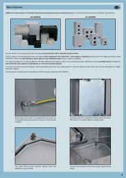
V-type locking system movementsOPENCLOSERaise the levers until the locking block is released.Insert the mobile connector until it comes into full contactwith the fixed part.Push the levers down and keep them outside thepegs on the hood.Raise the levers and turn them so that the ends are abovethe pegs on the hood.Remove the mobile connector from the fixed connector.Lower the levers until the locking mechanism isreleased.A feature of the V-type locking system is that in the final locking stage the levers work by pressing down vertically on top of the hood pegs thus minimizingfriction and wear and tear. The latch blocks on the enclosure pins that the levers are hinged to prevent the levers from being accidentally releasedeven if subjected to particularly heavy stresses.1
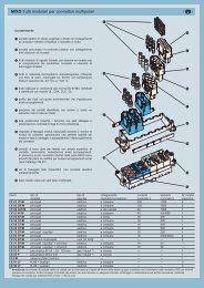
characteristics of complete connectors with V-type locking Threaded cable passing hole in various Pgdiameters (types with pre-code beginningwith ”C”) or metric pitch (types with precodebeginning with ”M”) in accordancewith CEI EN 60423, for cable entry devicesin accordance with EN 50262 (NPT threadingon request), may be located vertically,horizontally or frontally. Heavy-duty enclosures in die-cast aluminiumalloy.Wall mounting or bulkhead housings, andhoods are available. Metallic enclosures with a coated finish ofepoxy-polyester with high resistance tomechanical stress and external agents. Inserts in self-extinguishing thermoplasticmaterial reinforced with glass fibre, ULapproved, with working temperature rangingfrom -40 °C to +125 °C. Polarized inserts with asymmetric guiderails for preventing incorrect coupling.The inserts have a mechanical life of 500coupling cycles or above. Inserts manufactured in conformity with theEN 61984 European standard (DIN VDE0627) certified and identified with the ULmark (CSA pending). Special seal gaskets in anti-aging, oil-resistant,fuel-resistant vinyl nitrile elastomertogether with the cable entry devices (notsupplied) guarantee an IP65 degree of protectionfor coupled connectors. Stainless steel closure levers guaranteeperfect closure and sealing. Locking device available in two versions:simple (with one lever) or double (with twolevers). Insert captive screws with anti-looseningflexible washer. Position of contacts identified with numbersor codes on both sides of each insert andlaser printed or moulded. Silver-plated brass contacts with connectionsto conductors via specially suppliedcaptive pre-loosened screws or a springterminal. Earth terminal protection with wide contactsurface. CE marking attesting conformity to therequirements of the Low Voltage Directive73/23/EEC and its modification 93/68/EEC.2
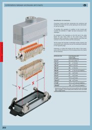
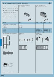
enclosure versions and applicationsstandard versiondescriptionChangeover from Pg threads to M metric threadsAfter 31st December 1999, the German safetystandard DIN VDE 0619 (1987-09) and the standardsit refers to - DIN 46319 for dimensions withmetric threads and DIN 46320 (T1-T4), DIN46255 and DIN 46259 for dimensions with Pgthreads (Panzerrohr-Gewinde=literally “steel conduitthreads” — were withdrawn and since 1January 2000 the European standard EN 50262“Metric cable glands for electrical installations”has been in force”. This standard defines the newsizes with metric threads for cable glands inaccordance with EN 60423 and establishes thesafety prescriptions. However, it does not specifythe dimensions such as the size of the tighteningwrench, the diagonal dimensions or the dimensionsof the seal gaskets as was the case in thewithdrawn DIN standards for Pg cable glands.The standard came definitively into force on 1April 2001, when the conflicting national standardswere withdrawn. It is valid in all CENELEC(the European Committee for ElectrotechnicalStandardization) member countries and its publicationhas led to an extension of the range ofenclosures for multipole connectors for industrialuse to include new enclosure versions with cableentries that are suitable for metric cable glands.Cable gland manufacturers have introduced thenew metric series alongside the Pg size seriesthat is will gradually replace. The transition periodindicated in the new standard should have endedon 1 March 2001 after which the use of Pg cableentry devices and, as a result, enclosures with Pgthreads, should no longer be used in new installations.However, both the cable entry devices andenclosures with Pg threading, may continue to beused as spare parts. For the CE marking of theseitems, the safety conditions specified in the LowVoltage Directive must be observed. To distinguishmobile and fixed surface mounting housingswith metric outlets from the Pg versions (markedwith a C pre-code), the ILME metric types aremarked with an M pre-code.The transposition table below indicates the correspondencerule adopted in most cases by ILMEfor creating the new metric versions.This series has been developed for applicationin electric and electronic machinery, controlunits, electric panels, control equipment, industrialenvironments, and whenever a disconnectableand reliable connection is required forpower and signal circuits.characteristics of the materials used:- in die-cast aluminium alloy- oven painting using epoxy-polyester powder- gaskets in anti-aging, oil-resistant, greaseresistantand fuel-resistant vinyl nitrile elastomer- locking device with stainless steel leversTransposition Pg ➔ metricPgmetricPg 11 M 20Pg 13.5 M 20Pg 16 M 20Pg 21 M 25Pg 29 M 32Pg 36 M 40Pg 42 M 503
conductor connectionscontacts with screw terminals connectionswith wire protectioncontacts with spring connection terminalsdescription description descriptionThe different types of conductor connections to themale and female inserts are described on the right.The types can be summarised as follows:- screw terminals- spring connection terminalsN.B.:for all inserts with screw terminals it is importantthat the right torsional torque is applied to thescrews in order to prevent faulty contacts or damageto the conductor, screw or terminal.inserts: CNEThe conductors are connected to the female and maleinsert contacts by screws (in accordance with EN60999-1 standard).with plateinserts: CSEThe conductors are connected to the male and femaleinsert contacts by spring terminals.This type of connection offers the following advantages:- no special preparation of the conductors is required- a 3.5 mm x 0.5 mm blade screw-driver is all that isneeded for inserting the conductor into the contact- an excellent degree of clamping is obtained with highresistance to strong vibrations- flexible and non-flexible conductors may be usedwith cable sections ranging from 0.14 mm to 2.5 mm 2- conductivity tests may be performed under loadthrough the screwdriver opening without disconnectingthe insert- preparation and insert cabling times are considerablyreducedThe CNE...T versions have a plastic cover that isused to guide the conductors into the contacts.phase 1insertion of the screwdriver into thesquare slot opens the base of theconductor obtained within thespring.phase 2deep insertion of the conductor inthe round base.phase 3extraction of the screwdriver determinesthe retention of the springon the inserted conductor.phase 4once the connection is complete, apulling action is to be applied totest the conductor’s retainingstrenght.4
<strong>CNZ</strong> complete connectors 16A max - 500V/6kV/3 (screw)V-type lever versionpart consisting of*:CNLZ IOCVI L + CNEF T + CNEM T + CHO LMNLZ IOCVI L + CNEF T + CNEM T + MHO LCNLZ IVCVI L + CNEF T + CNEM T + CHV LMNLZ IVCVI L + CNEF T + CNEM T + MHV Lbulkhead mounting housings with single lever,CNE series inserts, hoodside entrybulkhead mounting housings with single lever,CNE series inserts, hoodtop entry*(housing + female insert +male insert + hood)description part No. entry part No. entry part No. entry part No. entryPg M Pg Mwith lever, 6 poles + m, size ”44.27” CNLZ 06 IO 16 MNLZ 06 IO 25 CNLZ 06 IV 16 MNLZ 06 IV 25with lever, 10 poles + m, size ”57.27” CNLZ 10 IO 16 MNLZ 10 IO 25 CNLZ 10 IV 16 MNLZ 10 IV 25with lever, 16 poles + m, size ”77.27” CNLZ 16 IO 21 MNLZ 16 IO 32 CNLZ 16 IV 21 MNLZ 16 IV 32with lever, 24 poles + m, size ”104.27” CNLZ 24 IO 21 MNLZ 24 IO 32 CNLZ 24 IV 21 MNLZ 24 IV 32panel cut-out for bulkhead mounting housings in mmø 4.5dimensions in mmCNLZ/MNLZ IOdimensions in mmCNLZ/MNLZ IVPg/MPg/M13ABBB3235A 45,5C66A 45,5Ctype A BCNLZ/MNLZ 06 I 52 70CNLZ/MNLZ 10 I 65 83CNLZ/MNLZ 16 I 86 103CNLZ/MNLZ 24 I 112 130type A B CCNLZ/MNLZ 06 IO 82.5 74 66CNLZ/MNLZ 10 IO 95.5 79 70CNLZ/MNLZ 16 IO 115,5 90 70CNLZ/MNLZ 24 IO 142,5 90 70type A B CCNLZ/MNLZ 06 IV 82,5 67 66CNLZ/MNLZ 10 IV 95,5 72 70CNLZ/MNLZ 16 IV 115,5 72 70CNLZ/MNLZ 24 IV 142,5 82 70the indicated measurements are only approximate andcan be changed without prior notice6
<strong>CNZ</strong> complete connectors 16A max - 500V/6kV/3 (screw)V-type lever versionpart consisting of*:<strong>CNZ</strong> IOCVI + CNEF T + CNEM T + CHOMNZ IOCVI + CNEF T + CNEM T + MHO<strong>CNZ</strong> IVCVI + CNEF T + CNEM T + CHVMNZ IVCVI + CNEF T + CNEM T + MHV*(fixed enclosure + female insert +male insert + hood)bulkhead mounting housings with two levers,CNE series inserts, hoodsside entrybulkhead mounting housings with two levers,CNE series inserts, hoodstop entrydescription part No. entry part No. entry part No. entry part No. entryPg M Pg Mwith lever, 10 poles + m, size ”57.27” <strong>CNZ</strong> 10 IO 16 MNZ 10 IO 25 <strong>CNZ</strong> 10 IV 16 MNZ 10 IV 25with lever, 16 poles + m, size ”77.27” <strong>CNZ</strong> 16 IO 21 MNZ 16 IO 32 <strong>CNZ</strong> 16 IV 21 MNZ 16 IV 32with lever, 24 poles + m, size ”104.27” <strong>CNZ</strong> 24 IO 21 MNZ 24 IO 32 <strong>CNZ</strong> 24 IV 21 MNZ 24 IV 32panel cut-out for bulkhead mounting housings in mmø 4.5dimensions in mm<strong>CNZ</strong>/MNZ IOdimensions in mm<strong>CNZ</strong>/MNZ IV58Pg/M 58ABBPg/M13B3235AC 45,56AC 45,56type A B<strong>CNZ</strong>/MNZ 10 65 83<strong>CNZ</strong>/MNZ 16 86 103<strong>CNZ</strong>/MNZ 24 112 130type A B C<strong>CNZ</strong>/MNZ 10 IO 95.5 79 122<strong>CNZ</strong>/MNZ 16 IO 115.5 90 142,5<strong>CNZ</strong>/MNZ 24 IO 142.5 90 169type A B C<strong>CNZ</strong>/MNZ 10 IV 95.5 72 122<strong>CNZ</strong>/MNZ 16 IV 115.5 72 142,5<strong>CNZ</strong>/MNZ 24 IV 142.5 82 169the indicated measurements are only approximate andcan be changed without prior notice7
<strong>CNZ</strong> complete connectors 16A max - 500V/6kV/3 (screw)V-type lever versionpart consisting of*:CNLZ POCVP L + CNEF T + CNEM T + CHO LMNLZ POMVP L + CNEF T + CNEM T + MHO LCNLZ PVCVP L + CNEF T + CNEM T + CHV LMNLZ PVMVP L + CNEF T + CNEM T + MHV Lsurface mounting housings with single lever,CNE series inserts, hoodsside entrysurface mounting housings with single lever,CNE series inserts, hoodstop entry*(housing + female insert +male insert + hood)description part No. entry part No. entry part No. entry part No. entryPg M Pg Mwith lever, 6 poles + m, size ”44.27” CNLZ 06 PO 16 MNLZ 06 PO 20/25 CNLZ 06 PV 16 MNLZ 06 PV 20/25N.B.:entry M 20/25 =surface mounting housing M20 / hood M25dimensions in mmCNLZ/MNLZ POdimensions in mmCNLZ/MNLZ PVPg/MPg/M1398,57082Pg/MØ 5.54405291,57082Pg/MØ 5.5440527070the indicated measurements are only approximate andcan be changed without prior notice8
<strong>CNZ</strong> complete connectors 16A max - 500V/6kV/3 (screw)V-type lever versionpart consisting of*:<strong>CNZ</strong> POCVP + CNEF T + CNEM T + CHOMNZ POMVP + CNEF T + CNEM T + MHO<strong>CNZ</strong> PVCVP + CNEF T + CNEM T + CHVMNZ PVMVP + CNEF T + CNEM T + MHVsurface mounting housings with two levers,CNE series inserts, hoodsside entrysurface mounting housings with two levers,CNE series inserts, hoodstop entry*(housing + female insert +male insert + hood)description part No. entry part No. entry part No. entry part No. entryPg M Pg Mwith lever, 10 poles + m, size ”57.27” <strong>CNZ</strong> 10 PO 16 MNZ 10 PO 20/25 <strong>CNZ</strong> 10 PV 16 MNZ 10 PV 20/25with lever, 16 poles + m, size ”77.27” <strong>CNZ</strong> 16 PO 21 MNZ 16 PO 25/32 <strong>CNZ</strong> 16 PV 21 MNZ 16 PV 25/32with lever, 24 poles + m, size ”104.27” <strong>CNZ</strong> 24 PO 21 MNZ 24 PO 25/32 <strong>CNZ</strong> 24 PV 21 MNZ 24 PV 25/32N.B.:entry M 20/25 =surface mounting housing M20 / hood M25dimensions in mm<strong>CNZ</strong>/MNZ POdimensions in mm<strong>CNZ</strong>/MNZ PVentry M 25/32 =surface mounting housing M25 / hood M32Pg/M5813Pg/M58BEACØ 5.5Pg/M4FDBEACØ 5.5Pg/M4FDtype A B C D E F<strong>CNZ</strong>/MNZ 10 PO 93.5 107,5 122 52 82 40<strong>CNZ</strong>/MNZ 16 PO 117 124,5 142,5 57 105 45<strong>CNZ</strong>/MNZ 24 PO 144 124,5 169 57 132 45type A B C D E F<strong>CNZ</strong>/MNZ 10 PV 93.5 100,5 122 52 82 40<strong>CNZ</strong>/MNZ 16 PV 117 106,5 142,5 57 105 45<strong>CNZ</strong>/MNZ 24 PV 144 116,5 169 57 132 45the indicated measurements are only approximate andcan be changed without prior notice9
CSZ complete connectors 16A max - 500V/6kV/3 (spring)V-type lever versionpart consisting of*:CSLZ IOCVI L + CSEF + CSEM + CHO LMSLZ IOCVI L + CSEF + CSEM + MHO LCSLZ IVCVI L + CSEF + CSEM + CHV LMSLZ IVCVI L + CSEF + CSEM + MHV Lbulkhead mounting housings with single lever,CSE series inserts, hoodsside entrybulkhead mounting housings with single lever,CSE series inserts, hoodstop entry*(housing + female insert +male insert + hood)description part No. entry part No. entry part No. entry part No. entryPg M Pg Mwith lever, 6 poles + m, size ”44.27” CSLZ 06 IO 16 MSLZ 06 IO 25 CSLZ 06 IV 16 MSLZ 06 IV 25with lever, 10 poles + m, size ”57.27” CSLZ 10 IO 16 MSLZ 10 IO 25 CSLZ 10 IV 16 MSLZ 10 IV 25with lever, 16 poles + m, size ”77.27” CSLZ 16 IO 21 MSLZ 16 IO 32 CSLZ 16 IV 21 MSLZ 16 IV 32with lever, 24 poles + m, size ”104.27” CSLZ 24 IO 21 MSLZ 24 IO 32 CSLZ 24 IV 21 MSLZ 24 IV 32panel cut-out for bulkhead mounting housings in mmø 4.5dimensions in mmCSLZ/MSLZ IOdimensions in mmCSLZ/MSLZ IVPg/MPg/M13ABBB3235A 45,5C66A 45,5Ctype A BCSLZ/MSLZ 06 I 52 70CSLZ/MSLZ 10 I 65 83CSLZ/MSLZ 16 I 86 103CSLZ/MSLZ 24 I 112 130type A B CCSLZ/MSLZ 06 IO 82,5 74 66CSLZ/MSLZ 06 IO 95.5 79 70CSLZ/MSLZ 16 IO 115,5 90 70CSLZ/MSLZ 24 IO 142,5 90 70type A B CCSLZ/MSLZ 06 IV 82,5 67 66CSLZ/MSLZ 10 IV 95,5 72 70CSLZ/MSLZ 16 IV 115,5 72 70CSLZ/MSLZ 24 IV 142,5 82 70the indicated measurements are only approximate andcan be changed without prior notice12
CSZ complete connectors 16A max - 500V/6kV/3 (spring)V-type lever versionpart consisting of*:CSZ IOCVI + CSEF + CSEM + CHOMSZ IOCVI + CSEF + CSEM + MHOCSZ IVCVI + CSEF + CSEM + CHVMSZ IVCVI + CSEF + CSEM + MHV*(housing + female insert +male insert + hood)bulkhead mounting housings with two levers,CSE series inserts, hoodsside entrybulkhead mounting housings with two levers,CSE series inserts, hoodstop entrydescription part No. entry part No. entry part No. entry part No. entryPg M Pg Mwith lever, 10 poles + m, size ”57.27” CSZ 10 IO 16 MSZ 10 IO 25 CSZ 10 IV 16 MSZ 10 IV 25with lever, 16 poles + m, size ”77.27” CSZ 16 IO 21 MSZ 16 IO 32 CSZ 16 IV 21 MSZ 16 IV 32with lever, 24 poles + m, size ”104.27” CSZ 24 IO 21 MSZ 24 IO 32 CSZ 24 IV 21 MSZ 24 IV 32panel cut-out for bulkhead mounting housings in mmø 4.5dimensions in mmCSZ/MSZ IOdimensions in mmCSZ/MSZ IV58Pg/M 58ABBPg/M13B3235AC 45,56AC 45,56type A BCSZ/MSZ 10 65 83CSZ/MSZ 16 86 103CSZ/MSZ 24 112 130type A B CCSZ/MSZ 10 IO 95.5 79 122CSZ/MSZ 16 IO 115.5 90 142,5CSZ/MSZ 24 IO 142.5 90 169type A B CCSZ/MSZ 10 IV 95.5 72 122CSZ/MSZ 16 IV 115.5 72 142,5CSZ/MSZ 24 IV 1425, 82 169the indicated measurements are only approximate andcan be changed without prior notice13
CSZ complete connectors 16A max - 500V/6kV/3 (spring)V-type lever versionpart consisting of*:CSLZ POCVP L + CSEF + CSEM + CHO LMSLZ POMVP L + CSEF + CSEM + MHO LCSLZ PVCVP L + CSEF + CSEM + CHV LMSLZ PVMVP L + CSEF + CSEM + MHV Lsurface mounting housings with single lever,CSE series inserts, hoodsside entrysurface mounting housings with single lever,CSE series inserts, hoodstop entry*(housing + female insert +male insert + hood)description part No. entry part No. entry part No. entry part No. entryPg M Pg Mwith lever, 6 poles + m, size ”44.27” CSLZ 06 PO 16 MSLZ 06 PO 20/25 CSLZ 06 PV 16 MSLZ 06 PV 20/25N.B.:entry M 20/25 =surface mounting housing M20 / hood M25dimensions in mmCSLZ/MSLZ POdimensions in mmCSLZ/MSLZ PVPg/MPg/M1398,57082Pg/MØ 5.54405291,57082Pg/MØ 5.5440527070the indicated measurements are only approximate andcan be changed without prior notice14
CSZ complete connectors 16A max - 500V/6kV/3 (spring)V-type lever versionpart consisting of*:CSZ POCVP + CSEF + CSEM + CHOMSZ POMVP + CSEF + CSEM + MHOCSZ PVCVP + CSEF + CSEM + CHVMSZ PVMVP + CSEF + CSEM + MHVsurface mounting housings with two levers,CSE series inserts, hoodsside entrysurface mounting housings with two levers,CSE series inserts, hoodstop entry*(housing + female insert +male insert + hood)description part No. entry part No. entry part No. entry part No. entryPg M Pg Mwith lever, 10 poles + m, size ”57.27” CSZ 10 PO 16 MSZ 10 PO 20/25 CSZ 10 PV 16 MSZ 10 PV 20/25with lever, 16 poles + m, size ”77.27” CSZ 16 PO 21 MSZ 16 PO 25/32 CSZ 16 PV 21 MSZ 16 PV 25/32with lever, 24 poles + m, size ”104.27” CSZ 24 PO 21 MSZ 24 PO 25/32 CSZ 24 PV 21 MSZ 24 PV 25/32N.B.:entry M 20/25 =surface mounting housing M20 / hood M25dimensions in mmCSZ/MSZ POdimensions in mmCSZ/MSZ PVentry M 25/32 =surface mounting housing M25 / hood M32Pg/M5813Pg/M58BEACØ 5.5Pg/M4FDBEACØ 5.5Pg/M4FDtype A B C D E FCSZ/MSZ 10 PO 93.5 107,5 122 52 82 40CSZ/MSZ 16 PO 117 124,5 142,5 57 105 45CSZ/MSZ 24 PO 144 124,5 169 57 132 45type A B C D E FCSZ/MSZ 10 PV 93.5 100,5 122 52 82 40CSZ/MSZ 16 PV 117 106,5 142,5 57 105 45CSZ/MSZ 24 PV 144 116,5 169 57 132 45the indicated measurements are only approximate andcan be changed without prior notice15
CSZ complete connectors 16A max - 500V/6kV/3 (spring)V-type lever versionpart consisting of*:CSLZ VGCVV LG + CSEF + CSEM + CHV LMSLZ VGMVV LG + CSEF + CSEM + MHV LCSZ VGCVV G + CSEF + CSEM + CHVMSZ VGMVV G + CSEF + CSEM + MHV*(hood with lever(s) + female insert +male insert + hood)hoods with single lever,CSE series inserts, hoodstop entryhoods with single lever,CSE series inserts, hoodstop entrydescription part No. entry part No. entry part No. entry part No. entryPg M Pg Mwith lever(s), 6 poles + m, size ”44.27” CSLZ 06 VG 16 MSLZ 06 VG 25with lever(s), 10 poles + m, size ”57.27” CSZ 10 VG 16 MSZ 10 VG 25with lever(s), 16 poles + m, size ”77.27” CSZ 16 VG 21 MSZ 16 VG 32with lever(s), 24 poles + m, size ”104.27” CSZ 24 VG 21 MSZ 24 VG 32dimensions in mmCSLZ/MSLZ VGdimensions in mmCSZ/MSZ VG60Pg/M1343<strong>AP</strong>g/M134384BPg/M751365Pg/MC1357type A B CCSZ/MSZ 10 VG 73 94 122CSZ/MSZ 16 VG 93.5 94 142,5CSZ/MSZ 24 VG 120 114 169the indicated measurements are only approximate andcan be changed without prior notice16