2007 Police Interceptor Modifier Guide - Digital Ally, Inc.
2007 Police Interceptor Modifier Guide - Digital Ally, Inc. 2007 Police Interceptor Modifier Guide - Digital Ally, Inc.
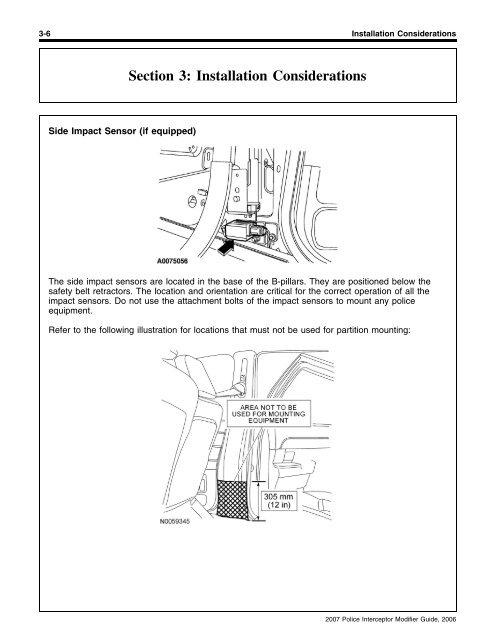
3-6 Installation ConsiderationsSection 3: Installation ConsiderationsSide Impact Sensor (if equipped)The side impact sensors are located in the base of the B-pillars. They are positioned below thesafety belt retractors. The location and orientation are critical for the correct operation of all theimpact sensors. Do not use the attachment bolts of the impact sensors to mount any policeequipment.Refer to the following illustration for locations that must not be used for partition mounting:2007 Police Interceptor Modifier Guide, 2006
Installation Considerations 3-7Section 3: Installation ConsiderationsConsole Design and InstallationRestraint Control Module (RCM)The restraint control module (RCM) is mounted on the center tunnel under the instrument panel.The RCM orientation is critical for proper operation of the restraint systems. Do not use the RCMmounting bolts for attachment purposes of any equipment.Air Bag Deployment InterferenceWARNING: Do not place objects or mount equipment in front of the air bag modulecover or in front seat areas that may come in contact with a deploying air bag. Dash, tunnelor console-mounted equipment should be placed within the specified zone. Dash, tunnel orconsole-mounted equipment should not be placed outside of the specified zone. Failure tofollow these instructions may result in personal injury.WARNING: Do not mount equipment between the side of the front seat and the doortrim that would block deployment of the side air bag. Failure to follow these instructionsmay result in personal injury.Driver/passenger air bags affect the way police equipment can be mounted in police vehicles. Anysurfaces that could come into contact with an air bag during deployment must not damage the airbag or alter its deployment path. Sharp edges, corners or protrusions could damage the nylon airbag material and reduce the effectiveness of the air bag. Do not mount or place any objects in thedeployment path of an air bag. Air bags must be allowed to fully deploy without restriction. Thedeployment of air bags is not compatible with any configuration of police equipment mounting thatplaces objects in the air bag deployment path. Equipment mounted or placed in the deploymentarea of an air bag will reduce the effectiveness of the air bag, damage the air bag and potentiallydamage or dislodge the equipment.Air bag deployment drawings are provided in Section 5. Consult the drawings before equipment isinstalled inside the passenger compartment to make sure that the mounted equipment does notinterfere with air bag deployment.Fire Suppression SystemThe fire suppression system works on similar principles as the restraints system. When installingadditional equipment, caution must be taken not to interfere with the fire suppression systemcomponents.2007 Police Interceptor Modifier Guide, 2006
- Page 36 and 37: Electrical 2-13Section 2: Electrica
- Page 38 and 39: Electrical 2-15Section 2: Electrica
- Page 40 and 41: Electrical 2-17Section 2: Electrica
- Page 42 and 43: Electrical 2-19Section 2: Electrica
- Page 44 and 45: Electrical 2-21Section 2: Electrica
- Page 46 and 47: Electrical 2-23Section 2: Electrica
- Page 48 and 49: Electrical 2-25Section 2: Electrica
- Page 50 and 51: Electrical 2-27Section 2: Electrica
- Page 52 and 53: Electrical 2-29Section 2: Electrica
- Page 54 and 55: Electrical 2-31Section 2: Electrica
- Page 56 and 57: Electrical 2-33Section 2: Electrica
- Page 58 and 59: Electrical 2-35Section 2: Electrica
- Page 60 and 61: Electrical 2-37Section 2: Electrica
- Page 62 and 63: Electrical 2-39Section 2: Electrica
- Page 64 and 65: Electrical 2-41Section 2: Electrica
- Page 66 and 67: Electrical 2-43Section 2: Electrica
- Page 68 and 69: Electrical 2-45Section 2: Electrica
- Page 70 and 71: Electrical 2-47Section 2: Electrica
- Page 72 and 73: Electrical 2-49Section 2: Electrica
- Page 74 and 75: Electrical 2-51Section 2: Electrica
- Page 76 and 77: Electrical 2-53Section 2: Electrica
- Page 78 and 79: Electrical 2-55Section 2: Electrica
- Page 80 and 81: SECTION 3Installation Consideration
- Page 82 and 83: 3-2 Installation ConsiderationsSect
- Page 84 and 85: 3-4 Installation ConsiderationsSect
- Page 88 and 89: 3-8 Installation ConsiderationsSect
- Page 90 and 91: 3-10 Installation ConsiderationsSec
- Page 92 and 93: Trunk Mounting Considerations 4-1Se
- Page 94 and 95: Trunk Mounting Considerations 4-3Se
- Page 96 and 97: Trunk Mounting Considerations 4-5Se
- Page 98 and 99: Trunk Mounting Considerations 4-7Se
- Page 100 and 101: Trunk Mounting Considerations 4-9Se
- Page 102 and 103: Trunk Mounting Considerations 4-11S
- Page 104 and 105: Reference Information 5-1Section 5:
- Page 106 and 107: Reference Information 5-3Section 5:
- Page 108 and 109: Reference Information 5-5Section 5:
- Page 110 and 111: Reference Information 5-7Section 5:
- Page 112 and 113: Reference Information 5-9Section 5:
- Page 114 and 115: Reference Information 5-11Section 5
- Page 116 and 117: Reference Information 5-13Section 5
- Page 118 and 119: Reference Information 5-15Section 5
- Page 120 and 121: Reference Information 5-17Section 5
- Page 122 and 123: Reference Information 5-19Section 5
- Page 124 and 125: Reference Information 5-21Section 5
- Page 126: Reference Information 5-23Section 5
3-6 Installation ConsiderationsSection 3: Installation ConsiderationsSide Impact Sensor (if equipped)The side impact sensors are located in the base of the B-pillars. They are positioned below thesafety belt retractors. The location and orientation are critical for the correct operation of all theimpact sensors. Do not use the attachment bolts of the impact sensors to mount any policeequipment.Refer to the following illustration for locations that must not be used for partition mounting:<strong>2007</strong> <strong>Police</strong> <strong>Interceptor</strong> <strong>Modifier</strong> <strong>Guide</strong>, 2006


