kn series gas boiler installation & operating ... - Agencespl.com
kn series gas boiler installation & operating ... - Agencespl.com kn series gas boiler installation & operating ... - Agencespl.com
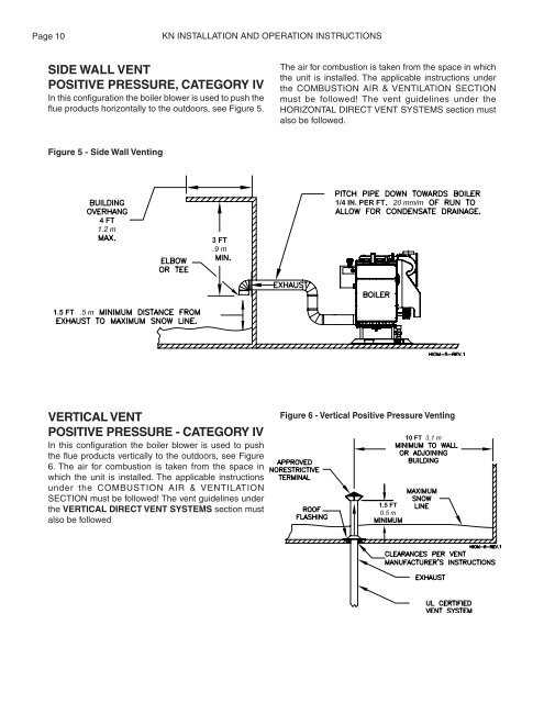
Page 10KN INSTALLATION AND OPERATION INSTRUCTIONSSIDE WALL VENTPOSITIVE PRESSURE, CATEGORY IVIn this configuration the boiler blower is used to push theflue products horizontally to the outdoors, see Figure 5.The air for combustion is taken from the space in whichthe unit is installed. The applicable instructions underthe COMBUSTION AIR & VENTILATION SECTIONmust be followed! The vent guidelines under theHORIZONTAL DIRECT VENT SYSTEMS section mustalso be followed.Figure 5 - Side Wall VentingVERTICAL VENTPOSITIVE PRESSURE - CATEGORY IVIn this configuration the boiler blower is used to pushthe flue products vertically to the outdoors, see Figure6. The air for combustion is taken from the space inwhich the unit is installed. The applicable instructionsunder the COMBUSTION AIR & VENTILATIONSECTION must be followed! The vent guidelines underthe VERTICAL DIRECT VENT SYSTEMS section mustalso be followedFigure 6 - Vertical Positive Pressure Venting
KN INSTALLATION AND OPERATION INSTRUCTIONSPage 11VERTICAL VENTNEGATIVE PRESSURE - CATEGORY IIThe KN is listed as a Category II appliance when ventedvertically into a listed metal chimney system, Figure 7.The chimney system must provide a negative pressureof 0.02 to 0.15 in, 0.51 to 3.81 mm W.C. at the boilerflue collar with the unit running.NOTE: When using a listed metal chimney systemthe chimney system manufacturer’s instructionsmust be followed.Multiple KN’s can be vented into a single verticalchimney system. Refer to HydroTherm KN-10 Ventingpage 7. Consult factory for multiple KN-6 and KN-20venting applications.When more than one appliance is connected to thesame chimney system the system must be large enoughto safely vent the combined output of all of theappliances.The vent system should be sloped up toward thechimney at a minimum rate of 1/4 in/ft, 2 cm/m.WARNING: Never install a vent pipe of adiameter different than that specified in Table 7.Failure to comply with this warning can resultin excessive levels of carbon monoxide whichcan cause severe personal injury or death.Always provide a minimum clearance of 6 in, 152 mmbetween single wall vent pipe and any combustiblematerials.WARNING: Failure to maintain minimumclearances between vent connectors and anycombustible material can result in a fire causingextensive property damage, severe personalinjury or death!Figure 7 - Vertical Venting with a Metal Chimney SystemTable 7 lists the equivalent breeching and chimneysizes required for a single boiler installation.WARNING: If an appliance using any type of amechanical draft system operating underpositive pressure is connected to a chimneyflue, never connect any other appliances to thisflue. Doing so can result in excessive levels ofcarbon monoxide which can cause severepersonal injury or death!Table 7 - Equivalent Breeching & Chimney Size,Negative Pressure - Single BoilerModel Breech & Flue DiameterSize in 2 mm 2600 8 2041000 12 3052000 18 457NOTE: These sizes are based on a 20 ft, 6.1mchimney height.Vent ConnectionsLocate the boiler as close to the chimney system aspossible. Use the shortest, straightest vent connectorpossible for the installation. If horizontal runs exceed5 ft, 1.5 m they must be supported at 3 ft, 0.9 mintervals with overhead hangers. Use the appropriatevent connector of the same diameter as the flue collarto connect the boiler to a listed metal chimney system.Follow the chimney system manufacturer’s instructionsfor proper assembly.
- Page 1 and 2: KN2-805KN SERIESGAS BOILERINSTALLAT
- Page 3 and 4: KN INSTALLATION AND OPERATION INSTR
- Page 5 and 6: KN INSTALLATION AND OPERATION INSTR
- Page 7 and 8: KN INSTALLATION AND OPERATION INSTR
- Page 9: KN INSTALLATION AND OPERATION INSTR
- Page 13 and 14: KN INSTALLATION AND OPERATION INSTR
- Page 15 and 16: KN INSTALLATION AND OPERATION INSTR
- Page 17 and 18: KN INSTALLATION AND OPERATION INSTR
- Page 19 and 20: KN INSTALLATION AND OPERATION INSTR
- Page 21 and 22: KN INSTALLATION AND OPERATION INSTR
- Page 23 and 24: KN INSTALLATION AND OPERATION INSTR
- Page 25 and 26: KN INSTALLATION AND OPERATION INSTR
- Page 27 and 28: KN INSTALLATION AND OPERATION INSTR
- Page 29 and 30: KN INSTALLATION AND OPERATION INSTR
- Page 31 and 32: KN INSTALLATION AND OPERATION INSTR
Page 10KN INSTALLATION AND OPERATION INSTRUCTIONSSIDE WALL VENTPOSITIVE PRESSURE, CATEGORY IVIn this configuration the <strong>boiler</strong> blower is used to push theflue products horizontally to the outdoors, see Figure 5.The air for <strong>com</strong>bustion is taken from the space in whichthe unit is installed. The applicable instructions underthe COMBUSTION AIR & VENTILATION SECTIONmust be followed! The vent guidelines under theHORIZONTAL DIRECT VENT SYSTEMS section mustalso be followed.Figure 5 - Side Wall VentingVERTICAL VENTPOSITIVE PRESSURE - CATEGORY IVIn this configuration the <strong>boiler</strong> blower is used to pushthe flue products vertically to the outdoors, see Figure6. The air for <strong>com</strong>bustion is taken from the space inwhich the unit is installed. The applicable instructionsunder the COMBUSTION AIR & VENTILATIONSECTION must be followed! The vent guidelines underthe VERTICAL DIRECT VENT SYSTEMS section mustalso be followedFigure 6 - Vertical Positive Pressure Venting


