MAX038 High-Frequency Waveform Generator
MAX038 High-Frequency Waveform Generator
MAX038 High-Frequency Waveform Generator

You also want an ePaper? Increase the reach of your titles
YUMPU automatically turns print PDFs into web optimized ePapers that Google loves.
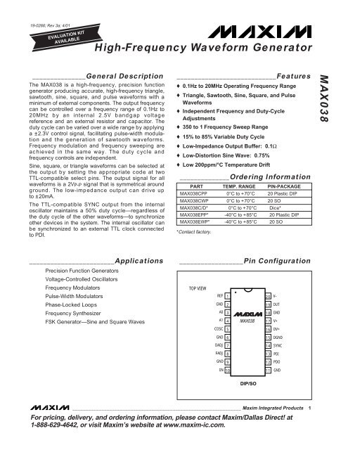
19-0266; Rev 3a; 4/01EVALUATION KITAVAILABLE<strong>High</strong>-<strong>Frequency</strong> <strong>Waveform</strong> <strong>Generator</strong>_______________General DescriptionThe <strong>MAX038</strong> is a high-frequency, precision functiongenerator producing accurate, high-frequency triangle,sawtooth, sine, square, and pulse waveforms with aminimum of external components. The output frequencycan be controlled over a frequency range of 0.1Hz to20MHz by an internal 2.5V bandgap voltagereference and an external resistor and capacitor. Theduty cycle can be varied over a wide range by applyinga ±2.3V control signal, facilitating pulse-width modulationand the generation of sawtooth waveforms.<strong>Frequency</strong> modulation and frequency sweeping areachieved in the same way. The duty cycle andfrequency controls are independent.Sine, square, or triangle waveforms can be selected atthe output by setting the appropriate code at twoTTL-compatible select pins. The output signal for allwaveforms is a 2VP-P signal that is symmetrical aroundground. The low-impedance output can drive upto ±20mA.The TTL-compatible SYNC output from the internaloscillator maintains a 50% duty cycle—regardless ofthe duty cycle of the other waveforms—to synchronizeother devices in the system. The internal oscillator canbe synchronized to an external TTL clock connectedto PDI.____________________________Features♦ 0.1Hz to 20MHz Operating <strong>Frequency</strong> Range♦ Triangle, Sawtooth, Sine, Square, and Pulse<strong>Waveform</strong>s♦ Independent <strong>Frequency</strong> and Duty-CycleAdjustments♦ 350 to 1 <strong>Frequency</strong> Sweep Range♦ 15% to 85% Variable Duty Cycle♦ Low-Impedance Output Buffer: 0.1Ω♦ Low-Distortion Sine Wave: 0.75%♦ Low 200ppm/°C Temperature Drift______________Ordering InformationPART TEMP. RANGE PIN-PACKAGE<strong>MAX038</strong>CPP 0°C to +70°C 20 Plastic DIP<strong>MAX038</strong>CWP 0°C to +70°C 20 SO<strong>MAX038</strong>C/D* 0°C to +70°C Dice*<strong>MAX038</strong>EPP* -40°C to +85°C 20 Plastic DIP<strong>MAX038</strong>EWP* -40°C to +85°C 20 SO*Contact factory.<strong>MAX038</strong>________________________ApplicationsPrecision Function <strong>Generator</strong>sVoltage-Controlled Oscillators<strong>Frequency</strong> ModulatorsPulse-Width ModulatorsPhase-Locked Loops<strong>Frequency</strong> SynthesizerFSK <strong>Generator</strong>—Sine and Square Waves__________________Pin ConfigurationTOP VIEWREFGNDA0A1COSC12345<strong>MAX038</strong>2019181716V-OUTGNDV+DV+GND615DGNDDADJ714SYNCFADJ813PDIGND912PDOIIN 1011GNDDIP/SO________________________________________________________________ Maxim Integrated Products 1For pricing, delivery, and ordering information, please contact Maxim/Dallas Direct! at1-888-629-4642, or visit Maxim’s website at www.maxim-ic.com.
<strong>High</strong>-<strong>Frequency</strong> <strong>Waveform</strong> <strong>Generator</strong><strong>MAX038</strong>ABSOLUTE MAXIMUM RATINGSV+ to GND ................................................................-0.3V to +6VDV+ to DGND...........................................................-0.3V to +6VV- to GND .................................................................+0.3V to -6VPin VoltagesIIN, FADJ, DADJ, PDO .....................(V- - 0.3V) to (V+ + 0.3V)COSC .....................................................................+0.3V to V-A0, A1, PDI, SYNC, REF.........................................-0.3V to V+GND to DGND ................................................................±0.3VMaximum Current into Any Pin .........................................±50mAOUT, REF Short-Circuit Duration to GND, V+, V- ...............30secContinuous Power Dissipation (T A = +70°C)Plastic DIP (derate 11.11mW/°C above +70°C) ..........889mWSO (derate 10.00mW/°C above +70°C).......................800mWCERDIP (derate 11.11mW/°C above +70°C)...............889mWOperating Temperature Ranges<strong>MAX038</strong>C_ _ .......................................................0°C to +70°C<strong>MAX038</strong>E_ _ ....................................................-40°C to +85°CMaximum Junction Temperature .....................................+150°CStorage Temperature Range .............................-65°C to +150°CLead Temperature (soldering, 10s) .............................+300°CStresses beyond those listed under “Absolute Maximum Ratings” may cause permanent damage to the device. These are stress ratings only, and functionaloperation of the device at these or any other conditions beyond those indicated in the operational sections of the specifications is not implied. Exposure toabsolute maximum rating conditions for extended periods may affect device reliability.ELECTRICAL CHARACTERISTICS(Circuit of Figure 1, GND = DGND = 0V, V+ = DV+ = 5V, V- = -5V, V DADJ = V FADJ = V PDI = V PDO = 0V, C F = 100pF,R IN = 25kΩ, R L = 1kΩ, C L = 20pF, T A = T MIN to T MAX , unless otherwise noted. Typical values are at T A = +25°C.)PARAMETER SYMBOL CONDITIONSMIN TYP MAX UNITSFREQUENCY CHARACTERISTICSMaximum Operating <strong>Frequency</strong> F o 15pCF ≤ 15pF, I IN = 500µA20.0 40.0 MHz<strong>Frequency</strong> ProgrammingV FADJ = 0V2.50 750ICurrentINV FADJ = -3V1.25 375µAIIN Offset Voltage V IN ±1.0 ±2.0 mV<strong>Frequency</strong> Temperature∆F o /°C V FADJ = 0V600CoefficientF o /°C V FADJ = -3V200ppm/°C(∆F o /F o )<strong>Frequency</strong> Power-Supply∆V+V- = -5V, V+ = 4.75V to 5.25V±0.4 ±2.00Rejection (∆F o /F o )∆V-V+ = 5V, V- = -4.75V to -5.25V±0.2 ±1.00%/VOUTPUT AMPLIFIER (applies to all waveforms)Output Peak-to-Peak Symmetry V OUT ±4 mVOutput Resistance R OUT 0.1 0.2 ΩOutput Short-Circuit Current I OUT Short circuit to GND40 mASQUARE-WAVE OUTPUT (R L = 100Ω)Amplitude V OUT 1.9 2.0 2.1 V P-PRise Time t R 10% to 90%12 nsFall Time t F 90% to 10%12 nsDuty Cycle dc V DADJ = 0V, dc = t ON /t x 100%47 50 53 %TRIANGLE-WAVE OUTPUT (R L = 100Ω)Amplitude V OUT 1.9 2.0 2.1 V P-PNonlinearity F o = 100kHz, 5% to 95%0.5 %Duty Cycle dc V DADJ = 0V (Note 1)47 50 53 %SINE-WAVE OUTPUT (R L = 100Ω)Amplitude V OUT 1.9 2.0 2.1 V P-PTotal Harmonic DistortionTHDDuty cycle adjusted to 50% 0.75Duty cycle unadjusted 1.50%2 _______________________________________________________________________________________
<strong>High</strong>-<strong>Frequency</strong> <strong>Waveform</strong> <strong>Generator</strong><strong>MAX038</strong>____________________________Typical Operating Characteristics (continued)(Circuit of Figure 1, V+ = DV+ = 5V, V- = -5V, V DADJ = V FADJ = V PDI = V PDO = 0V, R L = 1kΩ, C L = 20pF, T A = +25°C, unlessotherwise noted.)SQUARE-WAVE OUTPUT (20MHz)FREQUENCY MODULATION USING FADJI IN = 400µAC F = 20pFTOP: OUTPUTBOTTOM: FADJ0.5V0-0.5VFREQUENCY MODULATION USING I INFREQUENCY MODULATION USING I INTOP: OUTPUTBOTTOM: I INTOP: OUTPUTBOTTOM: I INPULSE-WIDTH MODULATION USING DADJ+1V0V-1V+2V0V-2VTOP: SQUARE-WAVE OUT, 2V P-PBOTTOM: V DADJ, -2V to +2.3V6 _______________________________________________________________________________________
<strong>High</strong>-<strong>Frequency</strong> <strong>Waveform</strong> <strong>Generator</strong>____________________________Typical Operating Characteristics (continued)(Circuit of Figure 1, V+ = DV+ = 5V, V- = -5V, V DADJ = V FADJ = V PDI = V PDO = 0V, R L = 1kΩ, C L = 20pF, T A = +25°C, unlessotherwise noted.)ATTENUATION (dB)0-10-20-30-40-50-60-70-80-90-100OUTPUT SPECTRUM, SINE WAVE(F o = 11.5MHz)R IN = 15kΩ (V IN = 2.5V), C F = 20pF,V DADJ = 40mV, V FADJ = -3V0 10 20 30 40 50 60 70 80 90 100FREQUENCY (MHz)<strong>MAX038</strong>-12AATTENUATION (dB)0-10-20-30-40-50-60-70-80-90-100OUTPUT SPECTRUM, SINE WAVE(F o = 5.9kHz)R IN = 51kΩ (V IN = 2.5V), C F = 0.01µF,V DADJ = 50mV, V FADJ = 0V0 5 10 15 20 25 30 35 40 45 50FREQUENCY (kHz)<strong>MAX038</strong> 12B<strong>MAX038</strong>______________________________________________________________Pin DescriptionPIN12, 6, 9,11, 18NAMEREFGND2.50V bandgap voltage reference outputGround*FUNCTION34578101213141516171920A0A1COSCDADJFADJIINPDOPDISYNCDGNDDV+V+OUTV-<strong>Waveform</strong> selection input; TTL/CMOS compatible<strong>Waveform</strong> selection input; TTL/CMOS compatibleExternal capacitor connectionDuty-cycle adjust input<strong>Frequency</strong> adjust inputCurrent input for frequency controlPhase detector output. Connect to GND if phase detector is not used.Phase detector reference clock input. Connect to GND if phase detector is not used.TTL/CMOS-compatible output, referenced between DGND and DV+. Permits the internal oscillator to besynchronized with an external signal. Leave open if unused.Digital groundDigital +5V supply input. Can be left open if SYNC is not used.+5V supply inputSine, square, or triangle output-5V supply input*The five GND pins are not internally connected. Connect all five GND pins to a quiet ground close to the device. A ground plane isrecommended (see Layout Considerations)._______________________________________________________________________________________ 7
<strong>High</strong>-<strong>Frequency</strong> <strong>Waveform</strong> <strong>Generator</strong><strong>MAX038</strong>5C F 68COSCGNDOSCILLATORTRIANGLEOSC AOSC BSINESHAPERTRIANGLESQUARESINE3 4A0A1MUXOUT197FADJDADJOSCILLATORCURRENTGENERATORCOMPARATORR LC L10IIN<strong>MAX038</strong>R F R D R IN-250µACOMPARATORSYNC141REF2.5VVOLTAGEREFERENCE+5V-5V*17202, 9, 11, 18V+V-GNDPHASEDETECTORPDOPDI1213DGNDDV+15 16*= SIGNAL DIRECTION, NOT POLARITY= BYPASS CAPACITORS ARE 1µF CERAMIC OR 1µF ELECTROLYTIC IN PARALLEL WITH 1nF CERAMIC.Figure 1. Block Diagram and Basic Operating Circuit*+5V_______________Detailed DescriptionThe <strong>MAX038</strong> is a high-frequency function generatorthat produces low-distortion sine, triangle, sawtooth, orsquare (pulse) waveforms at frequencies from less than1Hz to 20MHz or more, using a minimum of externalcomponents. <strong>Frequency</strong> and duty cycle can be independentlycontrolled by programming the current, voltage,or resistance. The desired output waveform isselected under logic control by setting the appropriatecode at the A0 and A1 inputs. A SYNC output andphase detector are included to simplify designs requiringtracking to an external signal source.The <strong>MAX038</strong> operates with ±5V ±5% power supplies.The basic oscillator is a relaxation type that operates byalternately charging and discharging a capacitor, CF,with constant currents, simultaneously producing a trianglewave and a square wave (Figure 1). The chargingand discharging currents are controlled by the currentflowing into IIN, and are modulated by the voltagesapplied to FADJ and DADJ. The current into IIN can bevaried from 2µA to 750µA, producing more than twodecades of frequency for any value of CF. Applying±2.4V to FADJ changes the nominal frequency (withVFADJ = 0V) by ±70%; this procedure can be used forfine control.Duty cycle (the percentage of time that the output waveformis positive) can be controlled from 10% to 90% byapplying ±2.3V to DADJ. This voltage changes the CFcharging and discharging current ratio while maintainingnearly constant frequency.8 _______________________________________________________________________________________
<strong>High</strong>-<strong>Frequency</strong> <strong>Waveform</strong> <strong>Generator</strong><strong>MAX038</strong>When the <strong>MAX038</strong>’s frequency is controlled by a voltagesource (VIN) in series with a fixed resistor (RIN), theoutput frequency is a direct function of VIN as shown inthe above equations. Varying VIN modulates the oscillatorfrequency. For example, using a 10kΩ resistor forR IN and sweeping VIN from 20mV to 7.5V produceslarge frequency deviations (up to 375:1). Select RIN sothat IIN stays within the 2µA to 750µA range. The bandwidthof the IIN control amplifier, which limits the modulatingsignal’s highest frequency, is typically 2MHz.IIN can be used as a summing point to add or subtractcurrents from several sources. This allows the outputfrequency to be a function of the sum of several variables.As VIN approaches 0V, the I IN error increasesdue to the offset voltage of IIN.Output frequency will be offset 1% from its final valuefor 10 seconds after power-up.FADJ InputThe output frequency can be modulated by FADJ,which is intended principally for fine frequency control,usually inside phase-locked loops. Once the fundamental,or center frequency (F o ) is set by IIN, it may bechanged further by setting FADJ to a voltage other than0V. This voltage can vary from -2.4V to +2.4V, causingthe output frequency to vary from 1.7 to 0.30 times thevalue when FADJ is 0V (Fo ±70%). Voltages beyond±2.4V can cause instability or cause the frequencychange to reverse slope.The voltage on FADJ required to cause the output todeviate from Fo by Dx (expressed in %) is given by theformula:VFADJ = -0.0343 x Dx [5]where VFADJ, the voltage on FADJ, is between-2.4V and +2.4V.Note: While IIN is directly proportional to the fundamental,or center frequency (F o ), VFADJ is linearly related to% deviation from F o . V FADJ goes to either side of 0V,corresponding to plus and minus deviation.The voltage on FADJ for any frequency is given by theformula:V FADJ = (F o - Fx) ÷ (0.2915 x Fo) [6]where:Fx = output frequencyFo = frequency when VFADJ = 0V.Likewise, for period calculations:VFADJ = 3.43 x (tx - to) ÷ tx [7]where:t x = output periodt o = period when V FADJ = 0V.Conversely, if VFADJ is known, the frequency is givenby:Fx = F o x (1 - [0.2915 x V FADJ ]) [8]and the period (tx) is:tx = to ÷ (1 - [0.2915 x VFADJ]) [9]Programming FADJFADJ has a 250µA constant current sink to V- that mustbe furnished by the voltage source. The source is usuallyan op-amp output, and the temperature coefficientof the current sink becomes unimportant. For manualadjustment of the deviation, a variable resistor can beused to set VFADJ, but then the 250µA current sink’stemperature coefficient becomes significant. Sinceexternal resistors cannot match the internal temperature-coefficientcurve, using external resistors to programVFADJ is intended only for manual operation,when the operator can correct for any errors. Thisrestriction does not apply when VFADJ is a true voltagesource.A variable resistor, RF, connected between REF (+2.5V)and FADJ provides a convenient means of manuallysetting the frequency deviation. The resistance value(RF) is:RF = (VREF - VFADJ) ÷ 250µA [10]VREF and VFADJ are signed numbers, so use correctalgebraic convention. For example, if VFADJ is -2.0V(+58.3% deviation), the formula becomes:RF = (+2.5V - (-2.0V)) ÷ 250µA= (4.5V) ÷ 250µA= 18kΩDisabling FADJThe FADJ circuit adds a small temperature coefficientto the output frequency. For critical open-loop applications,it can be turned off by connecting FADJ to GND(not REF) through a 12kΩ resistor (R1 in Figure 2). The-250µA current sink at FADJ causes -3V to be developedacross this resistor, producing two results. First,the FADJ circuit remains in its linear region, but disconnectsitself from the main oscillator, improving temperaturestability. Second, the oscillator frequency doubles.If FADJ is turned off in this manner, be sure to correctequations 1-4 and 6-9 above, and 12 and 14 below bydoubling Fo or halving to. Although this method doublesthe normal output frequency, it does not double theupper frequency limit. Do not operate FADJ open circuitor with voltages more negative than -3.5V. Doingso may cause transistor saturation inside the IC, leadingto unwanted changes in frequency and duty cycle.10 ______________________________________________________________________________________
<strong>High</strong>-<strong>Frequency</strong> <strong>Waveform</strong> <strong>Generator</strong>FREQUENCYC11µFC31nF1REF–5V +5V20 17 4V- V+ A13AOC21µF–2.5VPRECISION DUTY-CYCLE ADJUSTMENT CIRCUITR4100kR3100k+2.5VREF<strong>MAX038</strong>R IN20kR112k7DADJ <strong>MAX038</strong>R250Ω1019IINOUTSINE-WAVE8OUTPUTFADJ16DV+N.C.15DGND14SYNCN.C.13PDI5122 x 2.5VCOSCPDOF o =R IN x C FGND GND GND GND GNDC F 6 2 9 11 18R7100kR65kR5100kDADJ<strong>MAX038</strong>ADJUST R6 FOR MINIMUM SINE-WAVE DISTORTIONFigure 2. Operating Circuit with Sine-Wave Output and 50% Duty Cycle; SYNC and FADJ DisabledWith FADJ disabled, the output frequency can still bechanged by modulating I IN .Swept <strong>Frequency</strong> OperationThe output frequency can be swept by applying a varyingsignal to IIN or FADJ. IIN has a wider range, slightlyslower response, lower temperature coefficient, andrequires a single polarity current source. FADJ may beused when the swept range is less than ±70% of thecenter frequency, and it is suitable for phase-lockedloops and other low-deviation, high-accuracy closedloopcontrols. It uses a sweeping voltage symmetricalabout ground.Connecting a resistive network between REF, the voltagesource, and FADJ or IIN is a convenient means ofoffsetting the sweep voltage.Duty CycleThe voltage on DADJ controls the waveform duty cycle(defined as the percentage of time that the outputwaveform is positive). Normally, V DADJ = 0V, and theduty cycle is 50% (Figure 2). Varying this voltage from+2.3V to -2.3V causes the output duty cycle to varyfrom 15% to 85%, about -15% per volt. Voltagesbeyond ±2.3V can shift the output frequency and/orcause instability.DADJ can be used to reduce the sine-wave distortion.The unadjusted duty cycle (V DADJ = 0V) is 50% ±2%;any deviation from exactly 50% causes even order harmonicsto be generated. By applying a smalladjustable voltage (typically less than ±100mV) toV DADJ , exact symmetry can be attained and the distortioncan be minimized (see Figure 2).The voltage on DADJ needed to produce a specificduty cycle is given by the formula:V DADJ = (50% - dc) x 0.0575 [11]or:V DADJ = (0.5 - [t ON ÷ t o ]) x 5.75 [12]where:V DADJ = DADJ voltage (observe the polarity)dc = duty cycle (in %)t ON = ON (positive) timet o = waveform period.Conversely, if V DADJ is known, the duty cycle and ONtime are given by:dc = 50% - (V DADJ x 17.4) [13]t ON = t o x (0.5 - [V DADJ x 0.174]) [14]______________________________________________________________________________________ 11
<strong>High</strong>-<strong>Frequency</strong> <strong>Waveform</strong> <strong>Generator</strong>CENTERFREQUENCYR DSYNC DV+ V+ V- A113REFA07DADJ+5V -5V16 17 201019IINOUT8 <strong>MAX038</strong>FADJR PD13PDI512CCOSCPDOPD C FGND GND GND GND GND DGND2 6 9 11 18 15EXTERNAL OSC INPUT14PDO is a rectangular current-pulse train, alternatingbetween 0µA and 500µA. It has a 50% duty cycle whenthe <strong>MAX038</strong> output and PDI are in phase-quadrature(90° out of phase). The duty cycle approaches 100%as the phase difference approaches 180° and conversely,approaches 0% as the phase differenceapproaches 0°. The gain of the phase detector (KD)can be expressed as:KD = 0.318 x RPD (volts/radian) [16]where RPD = phase-detector gain-setting resistor.When the loop is in lock, the input signals to the phasedetector are in approximate phase quadrature, the dutycycle is 50%, and the average current at PDO is 250µA(the current sink of FADJ). This current is dividedbetween FADJ and RPD; 250µA always goes into FADJand any difference current is developed across RPD,creating VFADJ (both polarities). For example, as thephase difference increases, PDO duty cycle increases,the average current increases, and the voltage on RPD(and VFADJ) becomes more positive. This in turndecreases the oscillator frequency, reducing the phasedifference, thus maintaining phase lock. The higherRPD is, the greater VFADJ is for a given phase difference;in other words, the greater the loop gain, the lessthe capture range. The current from PDO must also4C11µFC21µFR OUT50ΩRFOUTPUTFigure 3. Phase-Locked Loop Using Internal Phase Detectorcharge CPD, so the rate at which VFADJ changes (theloop bandwidth) is inversely proportional to CPD.The phase error (deviation from phase quadrature)depends on the open-loop gain of the PLL and the initialfrequency deviation of the oscillator from the externalsignal source. The oscillator conversion gain (Ko) is:KO = ∆ω o ÷ ∆VFADJ [17]which, from equation [6] is:KO = 3.43 x ωo (radians/sec) [18]The loop gain of the PLL system (KV) is:KV = KD x KO [19]where:KD = detector gainKO = oscillator gain.With a loop filter having a response F(s), the open-looptransfer function, T(s), is:T(s) = KD x KO x F(s) ÷ s [20]Using linear feedback analysis techniques, the closedlooptransfer characteristic, H(s), can be related to theopen-loop transfer function as follows:H(s) = T(s) ÷ [1+ T(s)] [21]The transient performance and the frequency responseof the PLL depends on the choice of the filter characteristic,F(s).When the <strong>MAX038</strong> internal phase detector is not used,PDI and PDO should be connected to GND.External Phase DetectorsExternal phase detectors may be used instead of theinternal phase detector. The external phase detectorshown in Figure 4 duplicates the action of the <strong>MAX038</strong>’sinternal phase detector, but the optional ÷N circuit canbe placed between the SYNC output and the phasedetector in applications requiring synchronizing to anexact multiple of the external oscillator. The resistor networkconsisting of R4, R5, and R6 sets the sync range,while capacitor C4 sets the capture range. Note thatthis type of phase detector (with or without the ÷N circuit)locks onto harmonics of the external oscillator aswell as the fundamental. With no external oscillatorinput, this circuit can be unpredictable, depending onthe state of the external input DC level.Figure 4 shows a frequency phase detector that locksonto only the fundamental of the external oscillator.With no external oscillator input, the output of the frequencyphase detector is a positive DC voltage, andthe oscillations are at the lowest frequency as set byR4, R5, and R6.<strong>MAX038</strong>______________________________________________________________________________________ 13
<strong>High</strong>-<strong>Frequency</strong> <strong>Waveform</strong> <strong>Generator</strong><strong>MAX038</strong>÷NCENTERFREQUENCY1+5V -5V14 16 17 20 4SYNC DV+ V+ V- A1REFA03C11µFC21µFC WR2EXTERNALOSC INPUTPHASE DETECTORR4R5OFFSET-5VC4CAPTURER3R6GAINC3FREQUENCY71085DADJ <strong>MAX038</strong>IINFADJCOSCOUTPDIPDOGND GND GND GND GND DGND2 6 9 11 18 151312R150Ω19 RFOUTPUTFigure 4. Phase-Locked Loop Using External Phase Detector+5V -5VC11µF÷NCENTERFREQUENCY114 16 17 20 4SYNC DV+ V+ V- A1REFA03C21µFC WR2EXTERNALOSC INPUTFREQUENCY PHASE DETECTORR4R5OFFSET-5VC4CAPTURER3R6GAINC3FREQUENCY71085DADJ <strong>MAX038</strong>IINFADJCOSCOUTPDIPDOGND GND GND GND GND DGND2 6 9 11 18 15191312R150ΩRFOUTPUTFigure 5. Phase-Locked Loop Using External <strong>Frequency</strong> Phase Detector14 ______________________________________________________________________________________
<strong>High</strong>-<strong>Frequency</strong> <strong>Waveform</strong> <strong>Generator</strong><strong>MAX038</strong>11 20+2.5VVREF V-0.1µF0.1µFGND1OUTA0A1COSCGND1<strong>MAX038</strong>GNDV+DV+DGNDDADJ±2.5VFADJSYNCPDIGND1PDOIIN GND110 11OUT1RFBOUT2 VREFGNDVDDMX7541BIT1BIT12BIT2BIT1133k 0.1µF76MAX427423BIT3BIT10BIT4BIT5BIT9BIT83.3MBIT6BIT7910PDVPDR10k35pF7.5k0.1µF0.1µF+5V33k181k 1k1N9146 8MAX41272N390632N3904451MAX41220V TO 2.5V3.33k2µA to750µA2.7MWAVEFORMSELECT0.1µF 50.050Ω, 50MHzLOWPASS FILTER220nH 220nH50Ω0.1µF56pF 110pF 56pFSIGNALOUTPUT1003.3M0.1µFSYNCOUTPUT-5VFREQUENCY SYNTHESIZER 1kHz RESOLUTION; 8kHz TO 16.383MHz0.1µF1kHz2kHz4kHz8kHz16kHz32kHz64kHz128kHz256kHz512kHz1.024MHz2.048MHz4.096MHz8.192MHz15 14N4 N3N5N2N6N1N0FVPDVPDRRA2RA1RA0MC145151N7N8N9T/RN12N13N10N11 PD1OUTOSCOUT VDD8.192MHzOSCINVSSLDFIN28 120pF35pFFigure 6. Crystal-Controlled, Digitally Programmed <strong>Frequency</strong> Synthesizer—8kHz to 16MHz with 1kHz Resolution______________________________________________________________________________________ 15
<strong>High</strong>-<strong>Frequency</strong> <strong>Waveform</strong> <strong>Generator</strong><strong>MAX038</strong>Layout ConsiderationsRealizing the full performance of the <strong>MAX038</strong> requirescareful attention to power-supply bypassing and boardlayout. Use a low-impedance ground plane, and connectall five GND pins directly to it. Bypass V+ and V-directly to the ground plane with 1µF ceramic capacitorsor 1µF tantalum capacitors in parallel with 1nFceramics. Keep capacitor leads short (especially withthe 1nF ceramics) to minimize series inductance.If SYNC is used, DV+ must be connected to V+, DGNDmust be connected to the ground plane, and a second1nF ceramic should be connected as close as possiblebetween DV+ and DGND (pins 16 and 15). It is notnecessary to use a separate supply or run separatetraces to DV+. If SYNC is disabled, leave DV+ open.Do not open DGND.Minimize the trace area around COSC (and the groundplane area under COSC) to reduce parasitic capacitance,and surround this trace with ground to preventcoupling with other signals. Take similar precautionswith DADJ, FADJ, and IIN. Place CF so its connectionto the ground plane is close to pin 6 (GND).___________Applications Information<strong>Frequency</strong> SynthesizerFigure 6 shows a frequency synthesizer that producesaccurate and stable sine, square, or triangle waves witha frequency range of 8kHz to 16.383MHz in 1kHz increments.A Motorola MC145151 provides the crystal-controlledoscillator, the ÷N circuit, and a high-speed phasedetector. The manual switches set the output frequency;opening any switch increases the output frequency.Each switch controls both the ÷N output and anMX7541 12-bit DAC, whose output is converted to a currentby using both halves of the MAX412 op amp. Thiscurrent goes to the <strong>MAX038</strong> IIN pin, setting its coarsefrequency over a very wide range.Fine frequency control (and phase lock) is achievedfrom the MC145151 phase detector through the differentialamplifier and lowpass filter, U5. The phase detectorcompares the ÷N output with the <strong>MAX038</strong> SYNCoutput and sends differential phase information to U5.U5’s single-ended output is summed with an offset intothe FADJ input. (Using the DAC and the IIN pin forcoarse frequency control allows the FADJ pin to havevery fine control with reasonably fast response to switchchanges.)A 50MHz, 50Ω lowpass filter in the output allows passageof 16MHz square waves and triangle waves withreasonable fidelity, while stopping high-frequency noisegenerated by the ÷N circuit.___________________Chip TopographyAOA1COSCGNDDADJGND REF V- OUTFADJ GND IIN GND0.106"(2.692mm)PDOTRANSISTOR COUNT: 855SUBSTRATE CONNECTED TO GNDGNDV+DV+DGND0.118"(2.997mm)SYNCPDIMaxim cannot assume responsibility for use of any circuitry other than circuitry entirely embodied in a Maxim product. No circuit patent licenses areimplied. Maxim reserves the right to change the circuitry and specifications without notice at any time.16 ____________________Maxim Integrated Products, 120 San Gabriel Drive, Sunnyvale, CA 94086 408-737-7600© 2001 Maxim Integrated Products Printed USA is a registered trademark of Maxim Integrated Products.