262-30A Installation & Operation Manual - Crompton Instruments
262-30A Installation & Operation Manual - Crompton Instruments
262-30A Installation & Operation Manual - Crompton Instruments

Create successful ePaper yourself
Turn your PDF publications into a flip-book with our unique Google optimized e-Paper software.
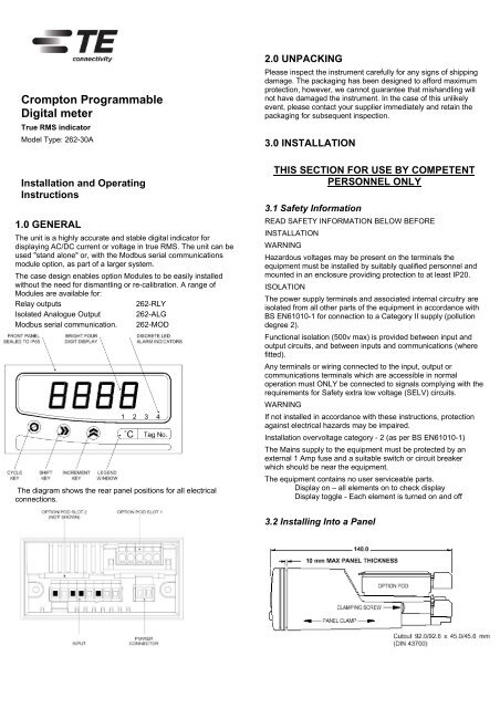
<strong>Crompton</strong> ProgrammableDigital meterTrue RMS indicatorModel Type: <strong>262</strong>-<strong>30A</strong><strong>Installation</strong> and OperatingInstructions1.0 GENERALThe unit is a highly accurate and stable digital indicator fordisplaying AC/DC current or voltage in true RMS. The unit can beused "stand alone" or, with the Modbus serial communicationsmodule option, as part of a larger system.The case design enables option Modules to be easily installedwithout the need for dismantling or re-calibration. A range ofModules are available for:Relay outputs<strong>262</strong>-RLYIsolated Analogue Output <strong>262</strong>-ALGModbus serial communication. <strong>262</strong>-MODThe diagram shows the rear panel positions for all electricalconnections.2.0 UNPACKINGPlease inspect the instrument carefully for any signs of shippingdamage. The packaging has been designed to afford maximumprotection, however, we cannot guarantee that mishandling willnot have damaged the instrument. In the case of this unlikelyevent, please contact your supplier immediately and retain thepackaging for subsequent inspection.3.0 INSTALLATIONTHIS SECTION FOR USE BY COMPETENTPERSONNEL ONLY3.1 Safety InformationREAD SAFETY INFORMATION BELOW BEFOREINSTALLATIONWARNINGHazardous voltages may be present on the terminals theequipment must be installed by suitably qualified personnel andmounted in an enclosure providing protection to at least IP20.ISOLATIONThe power supply terminals and associated internal circuitry areisolated from all other parts of the equipment in accordance withBS EN61010-1 for connection to a Category II supply (pollutiondegree 2).Functional isolation (500v max) is provided between input andoutput circuits, and between inputs and communications (wherefitted).Any terminals or wiring connected to the input, output orcommunications terminals which are accessible in normaloperation must ONLY be connected to signals complying with therequirements for Safety extra low voltage (SELV) circuits.WARNINGIf not installed in accordance with these instructions, protectionagainst electrical hazards may be impaired.<strong>Installation</strong> overvoltage category - 2 (as per BS EN61010-1)The Mains supply to the equipment must be protected by anexternal 1 Amp fuse and a suitable switch or circuit breakerwhich should be near the equipment.The equipment contains no user serviceable parts.Display on – all elements on to check displayDisplay toggle - Each element is turned on and off3.2 Installing Into a Panel
Refer to section 8.0 for Mechanical Detail.The maximum panel thickness is 10mm. The instrument casehas an integral gasket which forms a seal when the instrument istightened against the panel. The panel should be clean, smoothand at least 1.6mm thick for the seal to be effective.WARNING Use only the retaining screws provided to clamp theinstrument to the panel ( screws must be tightened sufficiently toeffect a seal but must never be overtightened).3.3 WiringAll connections are made to sockets which are removable forease of maintenance.<strong>Installation</strong> should be undertaken in accordance withrelevant sections of BS6739 - British Standards code ofpractice for "Instrumentation in Process Control Systems:<strong>Installation</strong> design and practice".3.4 Power SupplyThe Power supply rating will be indicated on the top of theinstrument, ensure it is correct for the application. The Mainssupply to the equipment must be protected by an external 1 Ampfuse and a suitable switch or circuit breaker which should be nearthe equipment.Wires are retained by screws. Ensure that the exposed section ofthe wire is fully inserted and that no loose strands are exposed.Connect only one input at any time to the indicator. Whereverpossible connect the neutral side or circuit common to the input -terminal.Ensure power is disconnected prior to wiring.4.0 PROGRAMMING THE INSTRUMENTThe unit is a microprocessor based instrument enabling it tosatisfy a variety of applications. All programming is available fromthe front panel or via a PC using the RS485 Modbuscommunications module.4.1 Programming GuideThe unit has three operating modes. These are :RUN (DISPLAYS PROCESS VARIABLE)MENUEDITRUN is the principal mode of operation, which displays theProcess Variable from which all other modes are accessed. Theunit will always time-out back to this mode after one minute.MENU mode provides access to the programmable parameters.EDIT mode is entered from Menu Mode and allows the user toinspect and modify a parameter.4.2 Key Definitions3.5 Input ConnectionsAll input connections are made via the eight way socket at therear of the unit (wire size 0 to 2.5mm²).Insert small screwdriver blade into tension clamp orifice, (1) pushand twist to deflect clamp into open position. Do not leverscrewdriver thus forcing connector body sideways. Insertconductor tail sufficiently into (2) then release screwdriver.Ensure no loose wire strands protrude.IsolationThe input is isolated by 3500V from the indicator circuitry andfrom the output options.The indicator is programmed using the three front panel keys,A,B and C are shown to assist the tutorial.CYCLE (A), SHIFT (B) and INC (C) keys are pressed singularly.ESCAPE (A&B), ENTER (B&C) and CLEAR (A&C) are obtainedby simultaneously pressing the two keys.4.3 Entering Menu ModeThe Root Menu mode is accessed from "Run" by pressingENTER (B&C) followed by CYCLE (A). The display will now show"inPt". In order to understand what this means, the followingdiagram shows where we are within the basic Root menu.* Slot menus only appear when respective option modules arefitted.
4.3.1 Moving Around The MenuOne can browse through the Root menu by pressing CYCLE (A)which moves the menu position from left to right (after reachingSYS, the menu position wraps around to the start).4.3.2 Entering A SubmenuTo enter a submenu, first cycle around the Root menu until therequired submenu is displayed. For the purposes of this tutorialpress the CYCLE (A) key until InPt is displayed. Pressing SHIFT(B) enters the Input Submenu.tYPe will now be displayed. The diagram shows our position inrelation to other items in the menu.Pressing CYCLE (A) moves left to right, wrapping around at theend. The unit alters items in the menu list depending uponsettings made.4.3.4 Returning From SubmenusTo return up from the inPt menu to the root menu wait for 1minute or press the ESCAPE (A&B) key.Pressing the ESCAPE key from our current position in the Inputssubmenu takes us back to the Root menu. The menu position willautomatically step to the next menu item, if no modules are fittedthe unit will show SYS, if modules are fitted SLt1 or SLt2 will beshown.The Root menu, as its name suggests is not a submenu.Pressing the ESCAPE (A&B) key sequence whilst in the Rootmenu will take the user out of Menu mode and into Run mode.Thus the process variable will be shown on the display. Refer tosection 5.2 if an error code is shown after programming in menumode.4.4 The Menus4.4.1 The INPt (INPUT) SubmenuThe INPt submenu is used to program all the characteristics ofthe input sensor and any signal conditioning that may berequired. The selection of an option in the list may affect itemsfurther down. Therefore, during programming, the user shouldstart at the top of the menu and work down, to avoid setting anoption which may later become obsolete. Short menu itemsshown in bold.4.3.3 Editing A ParameterThe items displayed in the menu can either be submenus,parameters or numbers, most of the items in the Inputs menu areparameters which can be edited.Press the CYCLE (A) key until tYPe is displayed, then pressSHIFT (B).The current setting will now be shown flashing. This item ischanged by pressing the INC (C) key.The choice of options available is as follows:TITLE OPTIONS DETAILtYPE 60V, 550V, 6A Input Type selectiondP 888.8, 88.88, 8.888, 8888 decimal point locationScAL User defined scale Multiplying factor applied toinputACDC AC, DC AC / DC SelectorFiLt nonE, 2.5, 10.5, Adaptive Input Filtering orSmoothing4.4.2 The SyS (System) SubmenuTITLE OPTIONS DETAILLiSt FuLL, SHrt Selects full or short menucLEn oFF, on Clear enable (option pods)SPEn oFF, on Setpoint enable (option pods)AdEL oFF,2,5,10,20, Power-up alarm delay60,120,240PASS 4 digit passcode Modify any password codeoFFS User defined Take care when replacing sensoroffsetRefer to section 7.0 for SLt menu structures.Press the INC (C) key until " 60V" is displayed.4.3.3 Editing A Parameter continuedNote that whilst the display is flashing, the option on the displayhas not been saved to memory. To select an option, the ENTERkey sequence is used. Press ENTER (B&C). The display will stopflashing momentarily before returning to Menu mode. The systemautomatically steps on to the next entry to speed the process ofprogramming. This method of editing parameters is repeatedthroughout the menu structure.5.0 OPERATION5.1 Run Mode <strong>Operation</strong>The normal display shown in this mode is the process variable.KEYPRESS ACTIONCYCLE (A) View setpoints(Adjust value if SPEn enabled)CLEAR (A&C) Reset relay latch and peak-valley(cLEn enabled)SHIFT (B) View peak memoryINC (C) View valley memory
5.2 Failure ModesIf the instrument detects an input, configuration or system errorthe effect upon the display and any output options fitted will bedetermined by the burnout setting in the input menu. These aresummarised below.6.0 SPECIFICATION @20 ºCSusceptibility BS EN50082-2ELECTRICAL SAFETY BS EN61010-1UL pendingEnvironmental Approvals for Tension ClampTerminalsLow Temperature IEC 68-2-1Dry Heat IEC 512-6-9Damp Heat IEC 512 -6-3Damp Heat cyclical IEC 68-2-30Salt Spray IEC 512-6-6Sulphur Dioxide IEC 68-2-46Hydrogen Sulphide IEC 68-2-16Gas TightnessIEC 512-Pr.11n7.0 OPTION MODULES7.0.1 Installing ModulesPower must be removed from unit before adding/removing amodule.Slot 1 (alarm 1 and 2) should be positioned on the left side of theunit looking from the front to correspond to front panel alarmindicator, slot 2 (alarm 3 and 4) is positioned on the right.6.1. Input SpecificationAccuracy0.1% of rdg/ ±0.1%FSDThermal Drift 0.02% / ºCInput Impedance 550V 10mΩ60V 1mΩ6A 0.02ΩIsolation 3.5KVRanges ±550Vdc ; 550Vac±60Vdc ; 60Vac±5A ; 5Aac6.2 General Specification @ 20 ºCInput/Output Isolation 3.5kVAC rms (galvanically isolated)Update time250 mS maximumTime Constant (Filter off)
7.1.1 SLT1, SLT2 (Relay Module) SubmenucontinuedHysteresis <strong>Operation</strong>Ripple Current 0mAMaximum Current Output < 23mAAccuracy0.07% or 5μA, which ever is greaterMaximum External Power Supply 30V (passive mode)Voltage Effect0.2μA / V* Connection of the link connects a 100 ohm termination resistoracross pins 7 and 8. This resistor should only be selected for theinstrument furthest away from the host.Full details of the modbus protocol are supplied separately withthe pod.
8.0 MECHANICAL DETAILMaterialWeightFlammabilityModule weightPanel cutoutABS/PC200gIEC707 FV040g typical92mm x 45mmWhile TE Connectivity (TE) has made every reasonable effort to ensure the accuracy of the information in this catalogue, TE does not guarantee that it is error-free, nor does TE make any other representation, warrantyor guarantee that the information is accurate, correct, reliable or current. TE reserves the right to make any adjustments to the information contained herein at any time without notice. TE expressly disclaims all impliedwarranties regarding the information contained herein, including, but not limited to, any implied warranties of merchantability or fitness for a particular purpose. The dimensions in this catalogue are for referencepurposes only and are subject to change without notice. Specifications are subject to change without notice. Consult TE for the latest dimensions and design specifications. TE Connectivity and TE Connectivity (logo)are trademarks. CROMPTON is a trademark of <strong>Crompton</strong> Parkinson Limited and is used under licence. Other trademarks are property of their respective owners.Tyco Electronics UK LimitedA TE Connectivity Ltd companyFreebournes Road, Witham, Essex, CM8 3AH, UKPhone: +44 (0)870 870 7500 Fax: +44 (0)870 240 5287www.crompton-instruments.com http://energy.te.com<strong>262</strong>-<strong>30A</strong> True RMS Indicator <strong>Installation</strong> and <strong>Operation</strong> <strong>Manual</strong>