Mobile Intel Pentium 4 Processor with 533 MHz Front Side Bus
Mobile Intel Pentium 4 Processor with 533 MHz Front Side Bus
Mobile Intel Pentium 4 Processor with 533 MHz Front Side Bus

Create successful ePaper yourself
Turn your PDF publications into a flip-book with our unique Google optimized e-Paper software.
<strong>Mobile</strong> <strong>Intel</strong> <strong>Pentium</strong> 4<strong>Processor</strong> <strong>with</strong> <strong>533</strong> <strong>MHz</strong> <strong>Front</strong><strong>Side</strong> <strong>Bus</strong>DatasheetJanuary 2004Order Number: 253028-004
Information in this document is provided solely to enable use of <strong>Intel</strong> products. <strong>Intel</strong> assumes no liability whatsoever, including infringement of anypatent or copyright, for sale and use of <strong>Intel</strong> products except as provided in <strong>Intel</strong>'s Terms and Conditions of Sale for such products. Informationcontained herein supersedes previously published specifications on these devices from <strong>Intel</strong>.Actual system-level properties, such as skin temperature, are a function of various factors, including component placement, component powercharacteristics, system power and thermal management techniques, software application usage and general system design. <strong>Intel</strong> is not responsiblefor its customers' system designs, nor is <strong>Intel</strong> responsible for ensuring that its customers' products comply <strong>with</strong> all applicable laws and regulations.<strong>Intel</strong> provides this and other thermal design information for informational purposes only. System design is the sole responsibility of <strong>Intel</strong>'s customers,and <strong>Intel</strong>'s customers should not rely on any <strong>Intel</strong>-provided information as either an endorsement or recommendation of any particular system designcharacteristics.Information in this document is provided in connection <strong>with</strong> <strong>Intel</strong> products. No license, express or implied, by estoppel or otherwise, to any intellectualproperty rights is granted by this document. Except as provided in <strong>Intel</strong>’s Terms and Conditions of Sale for such products, <strong>Intel</strong> assumes no liabilitywhatsoever, and <strong>Intel</strong> disclaims any express or implied warranty, relating to sale and/or use of <strong>Intel</strong> products including liability or warranties relating tofitness for a particular purpose, merchantability, or infringement of any patent, copyright or other intellectual property right. <strong>Intel</strong> products are notintended for use in medical, life saving, or life sustaining applications.<strong>Intel</strong> may make changes to specifications and product descriptions at any time, <strong>with</strong>out notice.Designers must not rely on the absence or characteristics of any features or instructions marked “reserved” or “undefined.” <strong>Intel</strong> reserves these forfuture definition and shall have no responsibility whatsoever for conflicts or incompatibilities arising from future changes to them.The mobile <strong>Intel</strong> <strong>Pentium</strong> 4 processor may contain design defects or errors known as errata which may cause the product to deviate from publishedspecifications. Current characterized errata are available on request.Contact your local <strong>Intel</strong> sales office or your distributor to obtain the latest specifications and before placing your product order.Copies of documents which have an ordering number and are referenced in this document, or other <strong>Intel</strong> literature, may be obtained by calling 1-800-548-4725 or by visiting <strong>Intel</strong>’s Website at http://www.intel.comCopyright © <strong>Intel</strong> Corporation 2003-2004<strong>Intel</strong>, <strong>Intel</strong> Logo, <strong>Pentium</strong>, <strong>Intel</strong> NetBurst, and <strong>Intel</strong> SpeedStep are registered trademarks or trademarks of <strong>Intel</strong> Corporation and its subsidiaries in theUnited States and other countries.* Other brands and names are the property of their respective owners.2 <strong>Mobile</strong> <strong>Intel</strong> ® <strong>Pentium</strong> ® 4 <strong>Processor</strong> <strong>with</strong> <strong>533</strong> <strong>MHz</strong> System <strong>Bus</strong> Datasheet
ContentsContents1 Introduction......................................................................................................................................91.1 Terminology ........................................................................................................................101.2 References .........................................................................................................................121.3 State of Data.......................................................................................................................122 Electrical Specifications.................................................................................................................132.1 FSB and GTLREF...............................................................................................................132.2 Power and Ground Pins......................................................................................................132.3 Decoupling Guidelines........................................................................................................132.3.1 VCC Decoupling ....................................................................................................142.3.2 FSB GTL+ Decoupling...........................................................................................142.4 Voltage Identification ..........................................................................................................142.4.1 Enhanced <strong>Intel</strong> SpeedStep® Technology..............................................................162.4.2 Phase Lock Loop (PLL) Power and Filter ..............................................................162.4.3 Catastrophic Thermal Protection ...........................................................................172.5 Signal Terminations, Unused Pins, and TESTHI[10:0].......................................................182.6 FSB Signal Groups .............................................................................................................192.7 Asynchronous GTL+ Signals ..............................................................................................212.8 Test Access Port (TAP) Connection ...................................................................................212.9 FSB Frequency Select Signals (BSEL[1:0]) .......................................................................212.10 Maximum Ratings ...............................................................................................................222.11 <strong>Processor</strong> DC Specifications ..............................................................................................222.11.1 Fixed <strong>Mobile</strong> Solution (FMS)..................................................................................222.12 VCC Overshoot Specification .............................................................................................312.12.1 Die Voltage Validation ...........................................................................................322.13 GTL+ FSB Specifications....................................................................................................333 Package Mechanical Specifications ..............................................................................................353.1 Package Load Specifications..............................................................................................403.2 <strong>Processor</strong> Insertion Specifications......................................................................................403.3 <strong>Processor</strong> Mass Specifications...........................................................................................403.4 <strong>Processor</strong> Materials ............................................................................................................413.5 <strong>Processor</strong> Markings ............................................................................................................413.6 <strong>Processor</strong> Pin-Out ..............................................................................................................414 Pin Listing and Signal Definitions ..................................................................................................434.1 <strong>Mobile</strong> <strong>Intel</strong> <strong>Pentium</strong> 4 <strong>Processor</strong> Pin Assignments ...........................................................434.2 Alphabetical Signals Reference..........................................................................................575 Thermal Specifications and Design Considerations ......................................................................655.1 <strong>Processor</strong> Thermal Specifications ......................................................................................655.1.1 Thermal Specifications ..........................................................................................655.1.2 Measurements for Thermal Specifications.............................................................665.1.2.1 <strong>Processor</strong> Case Temperature Measurement.........................................665.2 <strong>Processor</strong> Thermal Features ..............................................................................................675.2.1 <strong>Intel</strong> Thermal Monitor .............................................................................................675.2.2 On-Demand Mode .................................................................................................68<strong>Mobile</strong> <strong>Intel</strong> ® <strong>Pentium</strong> ® 4 <strong>Processor</strong> <strong>with</strong> <strong>533</strong> <strong>MHz</strong> System <strong>Bus</strong> Datasheet 3
Contents5.2.3 PROCHOT# Signal Pin.......................................................................................... 685.2.4 THERMTRIP# Signal Pin....................................................................................... 695.2.5 Thermal Diode ....................................................................................................... 696 Configuration and Low Power Features ........................................................................................ 716.1 Power-On Configuration Options........................................................................................ 716.2 Clock Control and Low Power States ................................................................................. 716.2.1 Normal State.......................................................................................................... 716.2.2 AutoHALT Powerdown State ................................................................................. 726.2.3 Stop-Grant State.................................................................................................... 726.2.4 HALT/Grant Snoop State....................................................................................... 736.2.5 Sleep State ............................................................................................................ 736.2.6 Deep Sleep State................................................................................................... 746.2.7 Deeper Sleep State ............................................................................................... 746.3 Enhanced <strong>Intel</strong> SpeedStep Technology ............................................................................. 747 Debug Tools Specifications ........................................................................................................... 757.1 Logic Analyzer Interface (LAI) ............................................................................................ 757.1.1 Mechanical Considerations.................................................................................... 757.1.2 Electrical Considerations ....................................................................................... 754 <strong>Mobile</strong> <strong>Intel</strong> ® <strong>Pentium</strong> ® 4 <strong>Processor</strong> <strong>with</strong> <strong>533</strong> <strong>MHz</strong> System <strong>Bus</strong> Datasheet
ContentsFigures1 VCCVID Pin Voltage and Current Requirements .......................................................................152 Phase Lock Loop (PLL) Filter Requirements.............................................................................173 Vcc Static and Transient Tolerance............................................................................................264 ITPCLKOUT[1:0] Output Buffer Diagram....................................................................................315 VCC Overshoot Example Waveform ..........................................................................................326 Test Circuit..................................................................................................................................347 Exploded View of <strong>Processor</strong> Components on a System Board..................................................358 <strong>Processor</strong> Package.....................................................................................................................369 Cross-Section and Keep-in.........................................................................................................3710 <strong>Processor</strong> Pin Detail ...................................................................................................................3811 IHS Flatness Specification..........................................................................................................3812 FC-PGA2 Package - Bottom View..............................................................................................3913 <strong>Processor</strong> Markings ....................................................................................................................4114 The Coordinates of the <strong>Processor</strong> Pins as Viewed from the Top of the Package. .....................4215 Guideline Locations for Case Temperature (TCASE) Thermocouple Placement.......................6716 Clock Control States ...................................................................................................................72<strong>Mobile</strong> <strong>Intel</strong> ® <strong>Pentium</strong> ® 4 <strong>Processor</strong> <strong>with</strong> <strong>533</strong> <strong>MHz</strong> System <strong>Bus</strong> Datasheet 5
ContentsTables1 References ................................................................................................................................. 122 VCCVID Pin Voltage Requirements ........................................................................................... 143 Voltage Identification Definition .................................................................................................. 154 FSB Pin Groups.......................................................................................................................... 205 BSEL[1:0] Frequency Table for BCLK[1:0]................................................................................. 216 <strong>Processor</strong> DC Absolute Maximum Ratings ................................................................................ 227 Voltage and Current Specifications ............................................................................................ 238 Vcc Static and Transient Tolerance............................................................................................ 259 FSB Differential BCLK Specifications......................................................................................... 2710 GTL+ Signal Group DC Specifications ....................................................................................... 2811 Asynchronous GTL+ Signal Group DC Specifications ............................................................... 2912 PWRGOOD and TAP Signal Group DC Specifications.............................................................. 3013 ITPCLKOUT[1:0] DC Specifications ........................................................................................... 3014 BSEL [1:0] and VID[4:0] DC Specifications ................................................................................ 3115 VCC Overshoot Specifications ................................................................................................... 3216 GTL+ <strong>Bus</strong> Voltage Definitions .................................................................................................... 3317 Description Table for <strong>Processor</strong> Dimensions ............................................................................. 3718 Package Dynamic and Static Load Specifications ..................................................................... 4019 <strong>Processor</strong> Mass.......................................................................................................................... 4020 <strong>Processor</strong> Material Properties .................................................................................................... 4121 Pin Listing by Pin Name ............................................................................................................. 4422 Pin Listing by Pin Number .......................................................................................................... 5023 Signal Description....................................................................................................................... 5724 <strong>Processor</strong> Thermal Design Power.............................................................................................. 6625 Thermal Diode Parameters ........................................................................................................ 7026 Thermal Diode Interface ............................................................................................................. 7027 Power-On Configuration Option Pins ......................................................................................... 716 <strong>Mobile</strong> <strong>Intel</strong> ® <strong>Pentium</strong> ® 4 <strong>Processor</strong> <strong>with</strong> <strong>533</strong> <strong>MHz</strong> System <strong>Bus</strong> Datasheet
ContentsRevision HistoryDocument ID Revision Description Date253028 001 Initial release of the Datasheet June 2003253028 002253028 003253028 004Updates include:• Added <strong>Intel</strong> HyperThreading Technology and 3.2-GHzspecs• Updated terminology “System <strong>Bus</strong>” to “<strong>Front</strong> <strong>Side</strong> <strong>Bus</strong>(FSB)’Updates include:• Updated Figure 13, “<strong>Processor</strong> Markings”Updates include:• Updated Table 17, “Description Table for <strong>Processor</strong>Dimensions “September 2003December 2003January 2004<strong>Mobile</strong> <strong>Intel</strong> ® <strong>Pentium</strong> ® 4 <strong>Processor</strong> <strong>with</strong> <strong>533</strong> <strong>MHz</strong> System <strong>Bus</strong> Datasheet 7
ContentsThis page intentionally left blank.8 <strong>Mobile</strong> <strong>Intel</strong> ® <strong>Pentium</strong> ® 4 <strong>Processor</strong> <strong>with</strong> <strong>533</strong> <strong>MHz</strong> System <strong>Bus</strong> Datasheet
Introduction1 IntroductionThe mobile <strong>Intel</strong> <strong>Pentium</strong> 4 processor <strong>with</strong> <strong>533</strong> <strong>MHz</strong> FSB is based on the <strong>Intel</strong> NetBurst TMmicro-architecture. The mobile <strong>Intel</strong> <strong>Pentium</strong> 4 processor <strong>with</strong> <strong>533</strong>-<strong>MHz</strong> FSB utilizes a 478-pinFlip-Chip Pin Grid Array (FC-PGA2) package <strong>with</strong> an integrated heat spreader, and plugs into asurface-mount, Zero Insertion Force (ZIF) socket. The mobile <strong>Intel</strong> <strong>Pentium</strong> 4 processor maintainsfull compatibility <strong>with</strong> IA-32 software. In this document the mobile <strong>Intel</strong> <strong>Pentium</strong> 4 processor <strong>with</strong><strong>533</strong> <strong>MHz</strong> FSB will be referred to as the “mobile <strong>Intel</strong> <strong>Pentium</strong> 4 processor <strong>with</strong> <strong>533</strong> <strong>MHz</strong> FSB”, or“mobile <strong>Intel</strong> <strong>Pentium</strong> 4 processor”, or simply “the processor”.The mobile <strong>Intel</strong> <strong>Pentium</strong> 4 processor <strong>with</strong> <strong>533</strong> <strong>MHz</strong> FSB supports Hyper-ThreadingTechnology, which allows a single, physical processor to function as two logical processors. Whilesome execution resources such as caches, execution units, and buses are shared, each logicalprocessor has its own architecture state <strong>with</strong> its own set of general-purpose registers, controlregisters to provide increased system responsiveness in multitasking environments, and headroomfor next generation multithreaded applications. <strong>Intel</strong> recommends enabling Hyper-ThreadingTechnology <strong>with</strong> Microsoft Windows* XP Professional or Windows* XP Home, and disablingHyper-Threading Technology via the BIOS for all previous versions of Windows operatingsystems. For more information on Hyper-Threading Technology, see www.intel.com/info/hyperthreading. Refer to Section 7.1 for Hyper-Threading Technology configuration details.The <strong>Intel</strong> NetBurst micro-architecture features include hyper-pipelined technology, a rapidexecution engine, a <strong>533</strong>-<strong>MHz</strong> FSB, and an execution trace cache. The hyper pipelined technologydoubles the pipeline depth in the mobile <strong>Intel</strong> <strong>Pentium</strong> 4 processor allowing the processor to reachmuch higher core frequencies. The rapid execution engine allows the two integer ALUs in theprocessor to run at twice the core frequency, which allows many integer instructions to execute in1/2 clock tick. The <strong>533</strong>-<strong>MHz</strong> FSB is a quad-pumped bus running off a 133-<strong>MHz</strong> system clockmaking 4.3 GB/sec data transfer rates possible. The execution trace cache is a first level cache thatstores approximately 12-k decoded micro-operations, which removes the instruction decodinglogic from the main execution path, thereby increasing performance.Additional features <strong>with</strong>in the <strong>Intel</strong> NetBurst micro-architecture include advanced dynamicexecution, advanced transfer cache, enhanced floating point and multi-media unit, and StreamingSIMD Extensions 2 (SSE2). The advanced dynamic execution improves speculative execution andbranch prediction internal to the processor. The advanced transfer cache is a 512-kB, on-die level 2(L2) cache. A newly implemented floating point and multi media unit provides superiorperformance for multi-media and mathematically intensive applications. Finally, SSE2 adds 144new instructions for double-precision floating point, SIMD integer, and memory management.Power management capabilities such as AutoHALT, Stop-Grant, Sleep, Deep Sleep, and DeeperSleep have been incorporated. The processor includes an address bus powerdown capability whichremoves power from the address and data pins when the FSB is not in use. This feature is alwaysenabled on the processor.The Streaming SIMD Extensions 2 (SSE2) enable break-through levels of performance inmultimedia applications including 3-D graphics, video decoding/encoding, and speech recognition.The new packed, double-precision, floating-point instructions enhance performance forapplications that require greater range and precision, including scientific and engineeringapplications and advanced 3-D geometry techniques, such as ray tracing.<strong>Mobile</strong> <strong>Intel</strong> ® <strong>Pentium</strong> ® 4 <strong>Processor</strong> <strong>with</strong> <strong>533</strong> <strong>MHz</strong> System <strong>Bus</strong> Datasheet 9
IntroductionThe processor’s <strong>533</strong> <strong>MHz</strong> <strong>Intel</strong> NetBurst micro-architecture FSB utilizes a split-transaction,deferred reply protocol like the <strong>Intel</strong> <strong>Pentium</strong> 4 processor. This FSB is not compatible <strong>with</strong> the P6processor family bus. The <strong>533</strong>-<strong>MHz</strong> <strong>Intel</strong> NetBurst micro-architecture FSB uses Source-Synchronous Transfer (SST) of address and data to improve performance by transferring data fourtimes per bus clock (4X data transfer rate, as in AGP 4X). Along <strong>with</strong> the 4X data bus, the addressbus can deliver addresses two times per bus clock and is referred to as a “double-clocked” or 2Xaddress bus. Working together, the 4X data bus and 2X address bus provide a data bus bandwidthof up to 4.3 Gbytes/second.The processor, when used in conjunction <strong>with</strong> the requisite <strong>Intel</strong> SpeedStep technology applet orits equivalent, supports Enhanced <strong>Intel</strong> SpeedStep technology, which enables real-time dynamicswitching of the voltage and frequency between two performance modes. This occurs by switchingthe bus ratios, core operating voltage, and core processor speeds <strong>with</strong>out resetting the system.The processor FSB uses GTL+ signalling technology. The mobile <strong>Intel</strong> <strong>Pentium</strong> 4 processor <strong>with</strong><strong>533</strong> <strong>MHz</strong> FSB is expected to be available at the following core frequencies:• 3.20 GHz (in Maximum Performance Mode at 1.55 V). This processor runs at 1.60 GHz (inBattery Optimized Mode at 1.20 V• 3.06 GHz (in Maximum Performance Mode at 1.55 V). This processor runs at 1.60 GHz (inBattery Optimized Mode at 1.20 V)• 2.80 GHz (in Maximum Performance Mode at 1.525 V). This processor runs at 1.60 GHz (inBattery Optimized Mode at 1.20 V)• 2.66 GHz (in Maximum Performance Mode at 1.525 V). This processor runs at 1.60 GHz (inBattery Optimized Mode at 1.20 V)• 2.40 GHz (in Maximum Performance Mode at 1.525 V). This processor runs at 1.60 GHz (inBattery Optimized Mode at 1.20 V)1.1 TerminologyA “#” symbol after a signal name refers to an active low signal, indicating a signal is in the activestate when driven to a low level. For example, when RESET# is low, a reset has been requested.Conversely, when NMI is high, a nonmaskable interrupt has occurred. In the case of signals wherethe name does not imply an active state but describes part of a binary sequence (such as address ordata), the “#” symbol implies that the signal is inverted. For example, D[3:0] = “HLHL” refers to ahex “A”, and D[3:0]# = “LHLH” also refers to a hex “A” (H= High logic level, L= Low logiclevel).“<strong>Front</strong> <strong>Side</strong> <strong>Bus</strong> (FSB)” refers to the interface between the processor and system core logic (a.k.a.the chipset components). The FSB is a multiprocessing interface to processors, memory, and I/O.Commonly used terms are explained here for clarification:• <strong>Processor</strong> — For this document, the term processor shall mean the mobile <strong>Intel</strong> <strong>Pentium</strong> 4processor <strong>with</strong> <strong>533</strong> <strong>MHz</strong> FSB in the 478-pin package.• Keep out zone — The area on or near the processor that system design can not utilize.• <strong>Intel</strong> 852 GME/PM chipsets — <strong>Mobile</strong> chipset that will support the mobile <strong>Intel</strong><strong>Pentium</strong> 4 processor <strong>with</strong> <strong>533</strong> <strong>MHz</strong> FSB.• <strong>Processor</strong> core — <strong>Mobile</strong> <strong>Intel</strong> <strong>Pentium</strong> 4 processor <strong>with</strong> <strong>533</strong> <strong>MHz</strong> FSB core die <strong>with</strong>integrated L2 cache.10 <strong>Mobile</strong> <strong>Intel</strong> ® <strong>Pentium</strong> ® 4 <strong>Processor</strong> <strong>with</strong> <strong>533</strong> <strong>MHz</strong> System <strong>Bus</strong> Datasheet
Introduction• FC-PGA2 package — Flip-Chip Pin Grid Array package <strong>with</strong> 50-mil pin pitch and IntegratedHeat Spreader• Integrated heat spreader — The surface used to make contact between a heatsink or otherthermal solution and the processor. Abbreviated IHS.<strong>Mobile</strong> <strong>Intel</strong> ® <strong>Pentium</strong> ® 4 <strong>Processor</strong> <strong>with</strong> <strong>533</strong> <strong>MHz</strong> System <strong>Bus</strong> Datasheet 11
Introduction1.2 ReferencesMaterial and concepts available in the following documents may be beneficial when reading thisdocument.Table 1.ReferencesDocumentOrder Number<strong>Intel</strong> 852GM/852PM Chipset Platforms Design Guide http://developer.intel.com<strong>Intel</strong> <strong>Mobile</strong> <strong>Processor</strong> Micro-FCPGA Package and Socket Manufacturingand Mechanical User’s Guidehttp://developer.intel.com<strong>Intel</strong> 852GM Chipset Datasheet http://developer.intel.com<strong>Intel</strong> Architecture Software Developer's Manual http://developer.intel.com<strong>Mobile</strong> <strong>Intel</strong> <strong>Pentium</strong> 4 <strong>Processor</strong> <strong>with</strong> <strong>533</strong> <strong>MHz</strong> FSB SpecificationUpdate253176Volume I: Basic ArchitectureVolume II: Instruction Set ReferenceVolume III: System Programming Guide<strong>Mobile</strong> <strong>Intel</strong> <strong>Pentium</strong> 4 <strong>Processor</strong> Thermal Design Guidelines forTransportable Systems<strong>Intel</strong> <strong>Pentium</strong> 4 <strong>Processor</strong> in the 478-pin Package <strong>Processor</strong> FloThermmodelsITP700 Debug Port Design Guidehttp://developer.intel.comNOTE: Contact your <strong>Intel</strong> representative for the latest revision and order number of this document.1.3 State of DataThe data contained <strong>with</strong>in this document represents the most accurate post-silicon informationavailable by the publication date. However, all data in this document is subject to change.12 <strong>Mobile</strong> <strong>Intel</strong> ® <strong>Pentium</strong> ® 4 <strong>Processor</strong> <strong>with</strong> <strong>533</strong> <strong>MHz</strong> System <strong>Bus</strong> Datasheet
Electrical Specifications2 Electrical Specifications2.1 FSB and GTLREFMost mobile <strong>Intel</strong> <strong>Pentium</strong> 4 processor FSB signals use Gunning Transceiver Logic (GTL+)signalling technology. As <strong>with</strong> the <strong>Intel</strong> P6 family of microprocessors, this signalling technologyprovides improved noise margins and reduced ringing through low-voltage swings and controllededge rates. The termination voltage level for the mobile <strong>Intel</strong> <strong>Pentium</strong> 4 processor GTL+ signals isV CC , which is the operating voltage of the processor core. Previous generations of <strong>Intel</strong> mobileprocessors utilize a fixed termination voltage known as V CCT . The use of a termination voltage thatis determined by the processor core allows better voltage scaling on the FSB for mobile <strong>Intel</strong><strong>Pentium</strong> 4 processor. Because of the speed improvements to data and address bus, signal integrityand platform design methods have become more critical than <strong>with</strong> previous processor families.Design guidelines for the mobile <strong>Intel</strong> <strong>Pentium</strong> 4 processor FSB will be detailed in the appropriateplatform design guidelines document listed in Table 1.The GTL+ inputs require a reference voltage (GTLREF), which is used by the receivers todetermine if a signal is a logical 0 or a logical 1. GTLREF must be generated on the system board.Termination resistors are provided on the processor silicon and are terminated to its core voltage(V CC ). <strong>Intel</strong>’s 852GME/852PM chipsets will also provide on-die termination, thus eliminating theneed to terminate the bus on the system board for most GTL+ signals. However, some GTL+signals do not include on-die termination and must be terminated on the system board. For moreinformation, refer to the appropriate platform design guidelines document listed in Table 1.The GTL+ bus depends on incident wave switching. Therefore, timing calculations for GTL+signals are based on flight time as opposed to capacitive deratings. Analog signal simulation of theFSB, including trace lengths, is highly recommended when designing a system.2.2 Power and Ground PinsFor clean on-chip power distribution, the mobile <strong>Intel</strong> <strong>Pentium</strong> 4 processor have 85 V CC(power)and 181 V SS (ground) inputs. All power pins must be connected to V CC , while all V SS pins must beconnected to a system ground plane.The processor V CC pins must be supplied <strong>with</strong> the voltagedetermined by the VID (Voltage ID) pins and the loadline specifications (see Figure 3).2.3 Decoupling GuidelinesDue to its large number of transistors and high internal clock speeds, the processor is capable ofgenerating large average current swings between low and full power states. This may causevoltages on power planes to sag below their minimum values if bulk decoupling is not adequate.Care must be taken in the board design to ensure that the voltage provided to the processor remains<strong>with</strong>in the specifications listed in Table 7. Failure to do so can result in timing violations and/oraffect the long term reliability of the processor. For further information and design guidelines, referto the appropriate platform design guidelines listed in Table 1.<strong>Mobile</strong> <strong>Intel</strong> ® <strong>Pentium</strong> ® 4 <strong>Processor</strong> <strong>with</strong> <strong>533</strong> <strong>MHz</strong> System <strong>Bus</strong> Datasheet 13
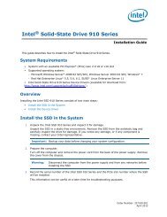
Electrical Specifications2.3.1 V CC DecouplingRegulator solutions need to provide bulk capacitance <strong>with</strong> a low Effective Series Resistance (ESR)and keep a low interconnect resistance from the regulator to the socket. Bulk decoupling for thelarge current swings when the part is powering on, or entering/exiting low-power states, must beprovided by the voltage regulator solution. For more details on decoupling recommendations,please refer to the appropriate platform design guidelines listed in Table 1.2.3.2 FSB GTL+ DecouplingThe mobile <strong>Intel</strong> <strong>Pentium</strong> 4 processor integrates signal termination on the die and incorporateshigh-frequency, decoupling capacitance on the processor package. Decoupling must also beprovided by the system motherboard for proper GTL+ bus operation. For more information, refer tothe appropriate platform design guidelines listed in Table 1.2.4 Voltage IdentificationThe voltage set by the VID pins is the maximum voltage allowed by the processor. A minimumvoltage is provided in Table 7 and changes <strong>with</strong> frequency. This allows processors running at ahigher frequency to have a relaxed minimum voltage specification. The specifications have beenset such that one voltage regulator can work <strong>with</strong> all supported frequencies.The mobile <strong>Intel</strong> <strong>Pentium</strong> 4 processor uses five voltage identification pins, VID[4:0], to supportautomatic selection of power supply voltages. The VID pins for the mobile <strong>Intel</strong> <strong>Pentium</strong> 4processor are open drain outputs driven by the processor VID circuitry. The VID signals rely onpull-up resistors tied to a 3.3-V (max) supply to set the signal to a logic high level. These pull-upresistors may be either external logic on the motherboard or internal to the Voltage Regulator.Table 3 specifies the voltage level corresponding to the state of VID[4:0]. A 1 in this table refers toa high-voltage level and a 0 refers to low-voltage level. If the processor socket is empty (VID[4:0]= 11111), or the voltage regulation circuit cannot supply the voltage that is requested, it mustdisable itself.Power source characteristics must be stable whenever the supply to the voltage regulator is stable.Refer to the Figure 14 for timing details of the power up sequence. Also refer to appropriateplatform design guidelines listed in Table 1 for implementation details.<strong>Mobile</strong> <strong>Intel</strong> <strong>Pentium</strong> 4 processor’s Voltage Identification circuit requires an independent 1.2-Vsupply. This voltage must be routed to the processor VCCVID pin. Figure 1 and Table 2 show thevoltage and current requirements of the VCCVID pin.Table 2.VCCVID Pin Voltage RequirementsSymbol Parameter Min Typ Max UnitVCCVID Vcc for voltage identification circuit -5% 1.2 +10% VNOTE: This specification applies to both static and transient components. The rising edge of VCCVID must bemonotonic from 0 to 1.1 V. See Figure 1 for current requirements. In this case, monotonic is defined ascontinuously increasing <strong>with</strong> less than 50 mV of peak to peak noise for any width greater than 2 nSsuperimposed on the rising edge.14 <strong>Mobile</strong> <strong>Intel</strong> ® <strong>Pentium</strong> ® 4 <strong>Processor</strong> <strong>with</strong> <strong>533</strong> <strong>MHz</strong> System <strong>Bus</strong> Datasheet
Electrical SpecificationsFigure 1. VCCVID Pin Voltage and Current Requirements1.2V+10%1.2V-5%1.0VVCCVID30mAVIDslatched1mA4nsTable 3. Voltage Identification Definition (Sheet 1 of 2)<strong>Processor</strong> PinsVID4 VID3 VID2 VID1 VID0 V CC_MAX1 1 1 1 1 VRM output off1 1 1 1 0 1.1001 1 1 0 1 1.1251 1 1 0 0 1.1501 1 0 1 1 1.1751 1 0 1 0 1.2001 1 0 0 1 1.2251 1 0 0 0 1.2501 0 1 1 1 1.2751 0 1 1 0 1.3001 0 1 0 1 1.3251 0 1 0 0 1.3501 0 0 1 1 1.3751 0 0 1 0 1.4001 0 0 0 1 1.4251 0 0 0 0 1.4500 1 1 1 1 1.4750 1 1 1 0 1.5000 1 1 0 1 1.5250 1 1 0 0 1.5500 1 0 1 1 1.575<strong>Mobile</strong> <strong>Intel</strong> ® <strong>Pentium</strong> ® 4 <strong>Processor</strong> <strong>with</strong> <strong>533</strong> <strong>MHz</strong> System <strong>Bus</strong> Datasheet 15
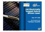
Electrical SpecificationsTable 3. Voltage Identification Definition (Sheet 2 of 2)0 1 0 1 0 1.6000 1 0 0 1 1.6250 1 0 0 0 1.6502.4.1 Enhanced <strong>Intel</strong> SpeedStep ® TechnologyThe mobile <strong>Intel</strong> <strong>Pentium</strong> 4 processor, when used in conjunction <strong>with</strong> the requisite <strong>Intel</strong>SpeedStep ® technology applet or its equivalent, supports Enhanced <strong>Intel</strong> SpeedStep technology.Enhanced <strong>Intel</strong> SpeedStep technology allows the processor to switch between two core frequenciesautomatically based on CPU demand, <strong>with</strong>out having to reset the processor or change the FSBfrequency. The processor operates in two modes, the Maximum Performance mode or the BatteryOptimized mode. Each frequency and voltage pair identifies the operating mode. The processordrives the VID[4:0] pins <strong>with</strong> the correct VID for the current operating mode. After reset, theprocessor will start in Battery Optimized mode. Any RESET# assertion will force the processor tothe Battery Optimized mode. INIT# assertions ("soft" resets) and APIC bus INIT messages do notchange the operating mode of the processor. Some electrical and thermal specifications are for aspecific voltage and frequency. The mobile <strong>Intel</strong> <strong>Pentium</strong> 4 processor featuring Enhanced <strong>Intel</strong>SpeedStep technology will meet the electrical and thermal specifications specific to the currentoperating mode, and it is not guaranteed to meet the electrical and thermal specifications specific tothe opposite operating mode. The timing specifications must be met when performing an operatingmode transition.2.4.2 Phase Lock Loop (PLL) Power and FilterV CCA and V CCIOPLL are power sources required by the PLL clock generators on the mobile <strong>Intel</strong><strong>Pentium</strong> 4 processor silicon. Since these PLLs are analog in nature, they require quiet powersupplies for minimum jitter. Jitter is detrimental to the system: it degrades external I/O timings aswell as internal core timings (i.e. maximum frequency). To prevent this degradation, these suppliesmust be low pass filtered from V CC .The AC low-pass requirements, <strong>with</strong> input at V CCVID is as follows:• < 0.2 dB gain in pass band• < 0.5 dB attenuation in pass band < 1 Hz• > 34 dB attenuation from 1 <strong>MHz</strong> to 66 <strong>MHz</strong>• > 28 dB attenuation from 66 <strong>MHz</strong> to core frequencyThe filter requirements are illustrated in Figure 2. For recommendations on implementing the filter,refer to the appropriate platform design guidelines listed in Table 1.16 <strong>Mobile</strong> <strong>Intel</strong> ® <strong>Pentium</strong> ® 4 <strong>Processor</strong> <strong>with</strong> <strong>533</strong> <strong>MHz</strong> System <strong>Bus</strong> Datasheet
Electrical Specifications.Figure 2. Phase Lock Loop (PLL) Filter Requirements0.2 dB0 dB-0.5 dBforbiddenzone-28 dB-34 dBforbiddenzoneDC1 Hzfpeak1 <strong>MHz</strong> 66 <strong>MHz</strong> fcorepassbandhigh frequencybandNOTES:1. Diagram not to scale.2. No specification for frequencies beyond fcore (core frequency).3. fpeak, if existent, should be less than 0.05 <strong>MHz</strong>.2.4.3 Catastrophic Thermal ProtectionThe mobile <strong>Intel</strong> <strong>Pentium</strong> 4 processor supports the THERMTRIP# signal for catastrophic thermalprotection. Alternatively, an external thermal sensor can be used to protect the processor and thesystem against excessive temperatures. Even <strong>with</strong> the activation of THERMTRIP#, which halts allprocessor internal clocks and activity, leakage current can be high enough such that the processorcannot be protected in all conditions <strong>with</strong>out the removal of power to the processor. If the externalthermal sensor detects a catastrophic processor temperature of 135°C (maximum), or if theTHERMTRIP# signal is asserted, the VCC supply to the processor must be turned off <strong>with</strong>in500 ms to prevent permanent silicon damage due to thermal runaway of the processor. Refer toSection 4.2 for more details on THERMTRIP#.<strong>Mobile</strong> <strong>Intel</strong> ® <strong>Pentium</strong> ® 4 <strong>Processor</strong> <strong>with</strong> <strong>533</strong> <strong>MHz</strong> System <strong>Bus</strong> Datasheet 17
Electrical Specifications2.5 Signal Terminations, Unused Pins, andTESTHI[10:0]All NC pins must remain unconnected. Connection of these pins to V CC , V SS , or to any other signal(including each other) can result in component malfunction or incompatibility <strong>with</strong> future mobile<strong>Intel</strong> <strong>Pentium</strong> 4 processors. See Section 5.2 for a pin listing of the processor and the location of allNC pins.For reliable operation, always connect unused inputs or bidirectional signals that are not terminatedon the die to an appropriate signal level. Note that on-die termination has been included on themobile <strong>Intel</strong> <strong>Pentium</strong> 4 processor to allow signals to be terminated <strong>with</strong>in the processor silicon.Unused active low GTL+ inputs may be left as no connects if GTL+ termination is provided on theprocessor silicon. Table 4 lists details on GTL+ signals that do not include on-die termination.Unused active high inputs should be connected through a resistor to ground (V SS ). Refer to theplatform design guidelines listed in Table 1 for the appropriate resistor values.Unused outputs can be left unconnected, however, this may interfere <strong>with</strong> some TAP functions,complicate debug probing, and prevent boundary scan testing. A resistor must be used when tyingbidirectional signals to power or ground. When tying any signal to power or ground, a resistor willalso allow for system testability. For unused GTL+ input or I/O signals that don’t have on-dietermination, use pull-up resistors of the same value in place of the on-die termination resistors(R TT ). See Table 16.The TAP, Asynchronous GTL+ inputs, and Asynchronous GTL+ outputs do not include on-dietermination. Inputs and used outputs must be terminated on the system board. Unused outputs maybe terminated on the system board or left unconnected. Note that leaving unused outputsunterminated may interfere <strong>with</strong> some TAP functions, complicate debug probing, and preventboundary scan testing. Signal termination for these signal types is discussed in the appropriateplatform design guidelines listed in Table 1. TAP signal termination requirements are alsodiscussed in ITP700 Debug Port Design Guide.The TESTHI pins should be tied to the processor V CC using a matched resistor, where a matchedresistor has a resistance value <strong>with</strong>in + 20% of the impedance of the board transmission line traces.For example, if the trace impedance is 50 , then a value between 40 and 60 is required.The TESTHI pins may use individual pull-up resistors or be grouped together as detailed below. Amatched resistor should be used for each group:1. TESTHI[1:0]2. TESTHI[5:2]3. TESTHI[10:8]Additionally, if the ITPCLKOUT[1:0] pins are not used then they may be connected individually toV CC using matched resistors or grouped <strong>with</strong> TESTHI[5:2] <strong>with</strong> a single matched resistor. If theyare being used, individual termination <strong>with</strong> 1-k resistors is required. Tying ITPCLKOUT[1:0]directly to V CC or sharing a pull-up resistor to V CC will prevent use of debug interposers. Thisimplementation is strongly discouraged for system boards that do not implement an onboard debugport.18 <strong>Mobile</strong> <strong>Intel</strong> ® <strong>Pentium</strong> ® 4 <strong>Processor</strong> <strong>with</strong> <strong>533</strong> <strong>MHz</strong> System <strong>Bus</strong> Datasheet
Electrical SpecificationsAs an alternative, group 2 (TESTHI[5:2]), and the ITPCLKOUT[1:0] pins may be tied directly tothe processor V CC . This has no impact on system functionality. TESTHI[0] may also be tieddirectly to processor V CC if resistor termination is a problem, but matched resistor termination isrecommended. In the case of the ITPCLKOUT[1:0] pins, direct tie to V CC is strongly discouragedfor system boards that do not implement an onboard debug port.Tying any of the TESTHI pins together will prevent the ability to perform boundary scan testing.Pullup/down resistor requirements for the VID[4:0] and BSEL[1:0] signals are included in thesignal descriptions in Section 4.2.6 FSB Signal GroupsIn order to simplify the following discussion, the FSB signals have been combined into groups bybuffer type. GTL+ input signals have differential input buffers, which use GTLREF as a referencelevel. In this document, the term "GTL+ Input" refers to the GTL+ input group as well as the GTL+I/O group when receiving. Similarly, "GTL+ Output" refers to the GTL+ output group as well as theGTL+ I/O group when driving.With the implementation of a source synchronous data bus comes the need to specify two sets oftiming parameters. One set is for common clock signals that are dependant upon the rising edge ofBCLK0 (ADS#, HIT#, HITM#, etc.) and the second set is for the source synchronous signalswhich are relative to their respective strobe lines (data and address) as well as the rising edge ofBCLK0. Asychronous signals are still present (A20M#, IGNNE#, etc.) and can become active atany time during the clock cycle. Table 4 identifies which signals are common clock, sourcesynchronous, and asynchronous.<strong>Mobile</strong> <strong>Intel</strong> ® <strong>Pentium</strong> ® 4 <strong>Processor</strong> <strong>with</strong> <strong>533</strong> <strong>MHz</strong> System <strong>Bus</strong> Datasheet 19
Electrical SpecificationsTable 4.FSB Pin GroupsSignal Group Type Signals 1GTL+ Common Clock InputGTL+ Common Clock I/OCommonclockSynchronousBPRI#, DEFER#, RESET# 2 , RS[2:0]#, RSP#, TRDY#AP[1:0]#, ADS#, BINIT#, BNR#, BPM[5:0]# 2 , BR0# 2 ,DBSY#, DP[3:0]#, DRDY#, HIT#, HITM#, LOCK#,MCERR#SignalsAssociated StrobeREQ[4:0]#, A[16:3]# 5ADSTB0#GTL+ Source SynchronousI/OSourceSynchronousA[35:17]# 5D[15:0]#, DBI0#ADSTB1#DSTBP0#, DSTBN0#D[31:16]#, DBI1#DSTBP1#, DSTBN1#D[47:32]#, DBI2#DSTBP2#, DSTBN2#D[63:48]#, DBI3#DSTBP3#, DSTBN3#GTL+ StrobesAsynchronous GTL+ Input 4,5CommonClockAsynchronousADSTB[1:0]#, DSTBP[3:0]#, DSTBN[3:0]#A20M#, DPSLP#, GHI#, IGNNE#, INIT# 5 , LINT0/INTR,LINT1/NMI, SMI# 5 , SLP#, STPCLK#Asynchronous GTL+ Output 4 Asynchronous FERR#/PBE#, IERR# 2 , THERMTRIP#Asynchronous GTL+ Input/Output 4 Asynchronous PROCHOT#TAP Input 4TAP Output 4Synchronousto TCKSynchronousto TCKTCK, TDI, TMS, TRST#TDOFSB Clock N/A BCLK[1:0], ITP_CLK[1:0] 3Power/OtherN/AV CC, V CCA, V CCIOPLL, VCCVID, VID[4:0], V SS, V SSA,GTLREF[3:0], COMP[1:0], NC, TESTHI[5:0],TESTHI[10:8], ITPCLKOUT[1:0], PWRGOOD,THERMDA, THERMDC, SKTOCC#, V CC_SENSE ,V SS_SENSE, BSEL[1:0], DBR# 3NOTES:1. Refer to Section 4.2 for signal descriptions.2. These GTL+ signals do not have on-die termination. Refer to Section 2.5 and the ITP700 Debug Port DesignGuide for termination requirements.3. In processor systems where there is no debug port implemented on the system board, these signals are usedto support a debug port interposer. In systems <strong>with</strong> the debug port implemented on the system board, thesesignals are no connects.4. These signal groups are not terminated by the processor. Signals not driven by the ICH4-M component mustbe terminated on the system board. Refer to Section 2.5, the ITP700 Debug Port Design Guide, and theappropriate platform design guidelines listed in Table 1 for termination requirements and further details.5. The value of these pins during the active-to-inactive edge of RESET# defines the processor configurationoptions. See Section 6.1 for details.20 <strong>Mobile</strong> <strong>Intel</strong> ® <strong>Pentium</strong> ® 4 <strong>Processor</strong> <strong>with</strong> <strong>533</strong> <strong>MHz</strong> System <strong>Bus</strong> Datasheet
Electrical Specifications2.7 Asynchronous GTL+ Signals<strong>Mobile</strong> <strong>Intel</strong> <strong>Pentium</strong> 4 processor does not utilize CMOS voltage levels on any signals that connectto the processor. As a result, legacy input signals such as A20M#, IGNNE#, INIT#, LINT0/INTR,LINT1/NMI, SMI#, SLP#, and STPCLK# use GTL+ input buffers. Legacy output FERR#/PBE#and other non-GTL+ signals (THERMTRIP#) utilize GTL+ output buffers. PROCHOT# usesGTL+ input/output buffer. All of these signals follow the same DC requirements as GTL+ signals,however the outputs are not actively driven high (during a logical 0 to 1 transition) by theprocessor. These signals do not have setup or hold time specifications in relation to BCLK[1:0].However, all of the Asynchronous GTL+ signals are required to be asserted for at least two BCLKsin order for the processor to recognize them. See Section 2.11 for the DC and AC specifications forthe Asynchronous GTL+ signal groups. See Section 6.2 for additional timing requirements forentering and leaving the low power states.2.8 Test Access Port (TAP) ConnectionDue to the voltage levels supported by other components in the Test Access Port (TAP) logic, it isrecommended that the mobile <strong>Intel</strong> <strong>Pentium</strong> 4 processor be first in the TAP chain and followed byany other components <strong>with</strong>in the system. A translation buffer should be used to connect to the restof the chain unless one of the other components is capable of accepting an input of the appropriatevoltage level. Similar considerations must be made for TCK, TMS, and TRST#. Two copies ofeach signal may be required, <strong>with</strong> each driving a different voltage level. Refer to ITP700 DebugPort Design Guide for more detailed information.2.9 FSB Frequency Select Signals (BSEL[1:0])The BSEL[1:0] are output signals used to select the frequency of the processor input clock(BCLK[1:0]). Table 5 defines the possible combinations of the signals and the frequencyassociated <strong>with</strong> each combination. The required frequency is determined by the processor, chipset,and clock synthesizer. All agents must operate at the same frequency.The mobile <strong>Intel</strong> <strong>Pentium</strong> 4 processor <strong>with</strong> <strong>533</strong> <strong>MHz</strong> FSB currently operates at a <strong>533</strong>-<strong>MHz</strong> FSBfrequency (selected by a 133-<strong>MHz</strong> BCLK[1:0] frequency). Individual processors will only operateat their specified FSB frequency.For more information about these pins refer to Section 4.2 and the appropriate platform designguidelines.Table 5.BSEL[1:0] Frequency Table for BCLK[1:0]BSEL1 BSEL0 FunctionL L RESERVEDL H 133 <strong>MHz</strong>H L RESERVEDH H RESERVED<strong>Mobile</strong> <strong>Intel</strong> ® <strong>Pentium</strong> ® 4 <strong>Processor</strong> <strong>with</strong> <strong>533</strong> <strong>MHz</strong> System <strong>Bus</strong> Datasheet 21
Electrical Specifications2.10 Maximum RatingsTable 6 lists the processor’s maximum environmental stress ratings. The processor should notreceive a clock while subjected to these conditions. Functional operating parameters are listed inthe AC and DC tables. Extended exposure to the maximum ratings may affect device reliability.Furthermore, although the processor contains protective circuitry to resist damage from electrostatic discharge (ESD), one should always take precautions to avoid high static voltages or electricfields.Table 6.<strong>Processor</strong> DC Absolute Maximum RatingsSymbol Parameter Min Max Unit NotesTSTORAGE<strong>Processor</strong> storagetemperature–40 85 °C 2V CCV inGTL+V inAsynch_GTL+Any processor supplyvoltage <strong>with</strong> respect to V SS-0.3 1.75 V 1GTL+ buffer DC inputvoltage <strong>with</strong> respect to V SS-0.1 1.75 VAsynch GTL+ buffer DCinput voltage <strong>with</strong> respect-0.1 1.75 Vto V SSI VID Max VID pin current 5 mANOTES:1. This rating applies to any processor pin.2. Contact <strong>Intel</strong> for storage requirements in excess of one year.2.11 <strong>Processor</strong> DC SpecificationsThe processor DC specifications in this section are defined at the processor core (pads) unlessnoted otherwise. See Chapter 5 for the pin signal definitions and signal pin assignments. Most ofthe signals on the processor FSB are in the GTL+ signal group. The DC specifications for thesesignals are listed in Table 10.Previously, legacy signals and Test Access Port (TAP) signals to the processor used low-voltageCMOS buffer types. However, these interfaces now follow DC specifications similar to GTL+. TheDC specifications for these signal groups are listed in Table 11 and Table 12.Table 7 through Table 14 list the DC specifications for the mobile <strong>Intel</strong> <strong>Pentium</strong> 4 processor andare valid only while meeting specifications for case temperature, clock frequency, and inputvoltages. Care should be taken to read all notes associated <strong>with</strong> each parameter.2.11.1 Fixed <strong>Mobile</strong> Solution (FMS)The FMS guidelines are estimates of the maximum values the mobile <strong>Intel</strong> <strong>Pentium</strong> 4 processorwill have over certain time periods. The values are only estimates and actual specifications forfuture processors may differ. The mobile <strong>Intel</strong> <strong>Pentium</strong> 4 processor may or may not havespecifications equal to the FMS value in the foreseeable future. System designers should meet theFMS values to ensure their systems will be compatible <strong>with</strong> future releases of the mobile <strong>Intel</strong><strong>Pentium</strong> 4 processor.22 <strong>Mobile</strong> <strong>Intel</strong> ® <strong>Pentium</strong> ® 4 <strong>Processor</strong> <strong>with</strong> <strong>533</strong> <strong>MHz</strong> System <strong>Bus</strong> Datasheet
Electrical SpecificationsTable 7.Voltage and Current SpecificationsSymbol Parameter Min Typ Max Unit NotesVcc for <strong>Processor</strong> atVID=1.200 V:Refer to Table 9and Figure 3V 2,3,4,5,101.60 GHz1.0701.140Vcc for <strong>Processor</strong> atVID=1.475 V:2.40 GHz2.66 GHz2.80 GHz3.06 GHz3.20 GHz1.3001.2951.2901.2651.2601.3801.3701.3701.3451.350Vcc for <strong>Processor</strong> atVID=1.500 VV CC2.40 GHz2.66 GHz2.80 GHz3.06 GHz3.20 GHz1.3251.3201.3151.2901.2851.4051.3951.3951.3701.370Vcc for <strong>Processor</strong> atVID=1.525 V2.40 GHz2.66 GHz2.80 GHz3.06 GHz3.20 GHz1.3551.3451.3401.3151.3101.4301.4201.4201.3951.395Vcc for <strong>Processor</strong> atVID=1.550 V3.06 GHz3.20 GHz1.3401.3351.4251.420I CCV CCDPRSLPI SGNTIslpI CC for <strong>Processor</strong> atVID=1.200 V:1.60 GHzI CC for <strong>Processor</strong><strong>with</strong> multiple VIDs:2.40 GHz2.66 GHz2.80 GHz3.06 GHz3.20 GHzStatic and TransientDeeper Sleep voltageI CC Stop-Grant at:VID = 1.200 VVID = 1.525 VVID = 1.550 V34.150.753.955.965.467.40.95 1.00 1.05 V 2202325A4,5,7,10A 6, 8, 10I TCC ICC TCC active ICC A 7I CC PLL ICC for PLL pins 60 mA 9<strong>Mobile</strong> <strong>Intel</strong> ® <strong>Pentium</strong> ® 4 <strong>Processor</strong> <strong>with</strong> <strong>533</strong> <strong>MHz</strong> System <strong>Bus</strong> Datasheet 23
Electrical SpecificationsNOTES:1. Unless otherwise noted, all specifications in this table are based on the latest silicon measurements availableat time of publication. Listed frequency and VID combinations are not necessarily committed productionfrequency and VID combinations.2. These voltages are targets only. A variable voltage source should exist on systems in the event that adifferent voltage is required. See Section 2.4 and Table 3 for more information. The VID bits will set themaximum V CC <strong>with</strong> the minimum being defined according to current consumption at that voltage.3. The voltage specification requirements are measured across V CCSENSE and V SSSENSE pins at the socket <strong>with</strong> a100-<strong>MHz</strong> bandwidth oscilloscope, 1.5-pF maximum probe capacitance, and 1-M minimum impedance. Themaximum length of ground wire on the probe should be less than 5 mm. Ensure external noise from thesystem is not coupled in the scope probe.4. Refer to Table 8, Table 9, and Figure 3 for the minimum, typical, and maximum V CC allowed for a givencurrent. The processor should not be subjected to any V CCand I CCcombination wherein V CCexceedsV CC_MAX for a given current. Moreover, V CC should never exceed the VID voltage. Failure to adhere to thisspecification can affect the long term reliability of the processor.5. V CC_MIN is defined at I CC_MAX .6. The current specified is also for AutoHALT state and applies to all frequencies.7. The maximum instantaneous current the processor will draw while the thermal control circuit is active asindicated by the assertion of PROCHOT# is the same as the maximum I CC for the processor.8. I CC Stop-Grant and I CC Sleep are specified at V CC_MAX .9. The specification is defined per PLL pin.10.The specifications for the Battery Optimized mode (1.60 GHz at 1.200 VID) are not 100% tested. Thesespecifications are determined by characterization of the processor currents at higher voltage and frequencyand extrapolating the values for the Battery Optimized mode voltage and frequency.24 <strong>Mobile</strong> <strong>Intel</strong> ® <strong>Pentium</strong> ® 4 <strong>Processor</strong> <strong>with</strong> <strong>533</strong> <strong>MHz</strong> System <strong>Bus</strong> Datasheet
Electrical SpecificationsTable 8.Vcc Static and Transient ToleranceIcc (A)Voltage Deviation from VID Setting (V) 1,2,3Maximum Typical Minimum0 0.000 -0.025 -0.0505 -0.010 -0.036 -0.06210 -0.019 -0.047 -0.07515 -0.029 -0.058 -0.08720 -0.038 -0.069 -0.09925 -0.048 -0.079 -0.11130 -0.057 -0.090 -0.12435 -0.067 -0.101 -0.13640 -0.076 -0.112 -0.14845 -0.085 -0.123 -0.16050 -0.095 -0.134 -0.17355 -0.105 -0.145 -0.18560 -0.114 -0.156 -0.19765 -0.124 -0.166 -0.20970 -0.133 -0.177 -0.222NOTES:1. The loadline specifications include both static and transient limits.2. This table is intended to aid in reading discrete points on the loadline figure below and applies to any VIDsetting.3. The loadlines specify voltage limits at the die measured at V CCSENSE and V SSSENSE pins. Voltage regulationfeedback for voltage regulator circuits must be taken from processor V CC and V SS pins.4. Adherence to this loadline specification for the mobile <strong>Intel</strong> <strong>Pentium</strong> 4 processor <strong>with</strong> <strong>533</strong> <strong>MHz</strong> FSB isrequired to ensure reliable processor operation.<strong>Mobile</strong> <strong>Intel</strong> ® <strong>Pentium</strong> ® 4 <strong>Processor</strong> <strong>with</strong> <strong>533</strong> <strong>MHz</strong> System <strong>Bus</strong> Datasheet 25
Electrical SpecificationsFigure 3. Vcc Static and Transient ToleranceVID+50mVVIDVID-50mVVccMaximumVID-100mVVID-150mVVccTypicalVID-200mVVccMinimumVID-250mV0 10 20 30 40 50 60 70Icc [A]NOTES:1. The loadline specification includes both static and transient limits.2. Refer to Table 8 for specific offsets from VID voltage which apply to all VID settings.3. The loadlines specify voltage limits at the die measured at V CC_sense and V ss_sense pins. Voltage regulationfeedback for voltage regulator circuits must be taken from processor V CC and V SS pins.4. Adherence to this loadline specification for the mobile <strong>Intel</strong> <strong>Pentium</strong> 4 processor <strong>with</strong> <strong>533</strong> <strong>MHz</strong> FSB isrequired to ensure reliable processor operation.26 <strong>Mobile</strong> <strong>Intel</strong> ® <strong>Pentium</strong> ® 4 <strong>Processor</strong> <strong>with</strong> <strong>533</strong> <strong>MHz</strong> System <strong>Bus</strong> Datasheet
Electrical SpecificationsTable 9.FSB Differential BCLK SpecificationsSymbol Parameter Min Typ Max Unit Figure Notes 1V LV HV CROSS(abs)Input LowVoltageInput HighVoltageAbsoluteCrossing Point-0.150 0.000 N/A V 80.660 0.700 0.850 V 80.250 N/A 0.550 V 8, 9 2,3,8V CROSS(rel)V CROSSRelativeCrossing PointRange ofCrossing Points0.250 +0.5(V Havg - 0.700)N/A0.550 +0.5(V Havg - 0.700)V 8, 9 2,3,8,9N/A N/A 0.140 V 8, 9 2,10V OV Overshoot N/A N/A V H + 0.3 V 8 4V US Undershoot -0.300 N/A N/A V 8 5V RBMV TMRingbackMarginThresholdMargin0.200 N/A N/A V 8 6V CROSS - 0.100 N/A V CROSS + 0.100 V 8 7NOTES:1. Unless otherwise noted, all specifications in this table apply to all processor frequencies.2. Crossing voltage is defined as the instantaneous voltage value when the rising edge of BCLK0 equals thefalling edge of BCLK1.3. V Havg is the statistical average of the V H measured by the oscilloscope.4. Overshoot is defined as the absolute value of the maximum voltage.5. Undershoot is defined as the absolute value of the minimum voltage.6. Ringback Margin is defined as the absolute voltage difference between the maximum Rising Edge Ringbackand the maximum Falling Edge Ringback.7. Threshold region is defined as a region entered around the crossing point voltage in which the differentialreceiver switches. It includes input threshold hysteresis.8. The crossing point must meet the absolute and relative crossing point specifications simultaneously.9. V Havg can be measured directly using "Vtop" on Agilent* scopes and "High" on Tektronix* scopes.10. V CROSS is defined as the total variation of all crossing voltages as defined in note 2.<strong>Mobile</strong> <strong>Intel</strong> ® <strong>Pentium</strong> ® 4 <strong>Processor</strong> <strong>with</strong> <strong>533</strong> <strong>MHz</strong> System <strong>Bus</strong> Datasheet 27
Electrical SpecificationsTable 10. GTL+ Signal Group DC SpecificationsSymbol Parameter Min Max Unit Notes 1GTLREF Reference Voltage 2/3 Vcc - 2% 2/3 Vcc + 2% V 10GTLREF_COMPATIBLE Reference Voltage 0.63*Vcc - 2% 0.63*Vcc + 2% V 10VIH Input High Voltage 1.10*GTLREF VCC V 2,6VIL Input Low Voltage 0.0 0.9*GTLREF V 3,4,6VOH Output High Voltage N/A Vcc V 7IOL Output Low Current N/A 50 mA 6IHI Pin Leakage High N/A 100 µA 8ILO Pin Leakage Low N/A 500 µA 9RON Buffer On Resistance 7 11 5, 11RON_COMPATIBLE Buffer On Resistance 8.4 13.2 5, 11NOTES:1. Unless otherwise noted, all specifications in this table apply to all processor frequencies.2. VIL is defined as the maximum voltage level at a receiving agent that will be interpreted as a logical low value.3. VIH is defined as the minimum voltage level at a receiving agent that will be interpreted as a logical highvalue.4. VIH and VOH may experience excursions above V CC . However, input signal drivers must comply <strong>with</strong> thesignal quality specifications in Section 3.5. Refer to processor I/O Buffer Models for I/V characteristics.6. The V CC referred to in these specifications is the instantaneous V CC .7. Vol max of 0.450 Volts is guaranteed when driving into a test load of 50 as indicated in Figure 6.8. Leakage to V SS <strong>with</strong> pin held at V CC .9. Leakage to V CC <strong>with</strong> pin held at 300 mV.10.For a platform to be forward compatible <strong>with</strong> future portable processors it must be designed to support anGTLREF value of 0.63*Vcc -2%(min) and 0.63*Vcc+2%(max). A compatible platform is one that is designedfor some level of compatibility <strong>with</strong> future portable processors.11.For a platform to be forward compatible <strong>with</strong> future portable processors it must be designed to support anRon value of 8.4 (min) and 13.2 (max). A compatible platform is one that is designed for some level ofcompatibility <strong>with</strong> future portable processors.28 <strong>Mobile</strong> <strong>Intel</strong> ® <strong>Pentium</strong> ® 4 <strong>Processor</strong> <strong>with</strong> <strong>533</strong> <strong>MHz</strong> System <strong>Bus</strong> Datasheet
Electrical SpecificationsTable 11. Asynchronous GTL+ Signal Group DC SpecificationsSymbol Parameter Min Max Unit Notes 1VIHInput High Voltage 1.10*GTLREF VCCAsynch GTL+V 3, 4, 5VILInput Low VoltageAsynch. GTL+0 0.9*GTLREF V 5VOH Output High Voltage N/A V CC V 2, 3, 4IOL Output Low Current N/A 50 mA 6, 8I HI Pin Leakage High N/A 100 µA 9I LO Pin Leakage Low N/A 500 µA 10RonRON_COMPATIBLEBuffer On ResistanceAsynch GTL+Buffer On ResistanceAsynch GTL+7 11 5, 78.4 13.2 11NOTES:1. Unless otherwise noted, all specifications in this table apply to all processor frequencies.2. All outputs are open-drain.3. V IH and V OH may experience excursions above V CC . However, input signal drivers must comply <strong>with</strong> thesignal quality specifications in Chapter 3.4. The V CC referred to in these specifications refers to instantaneous V CC .5. This specification applies to the asynchronous GTL+ signal group.6. The maximum output current is based on maximum current handling capability of the buffer and is notspecified into the test load shown in Figure 6.7. Refer to the processor I/O Buffer Models for I/V characteristics.8. Vol max of 0.270 Volts is guaranteed when driving into a test load of 50 as indicated in Figure 6 for theAsynchronous GTL+ signals.9. Leakage to V SS <strong>with</strong> pin held at V CC .10.Leakage to V CC <strong>with</strong> pin held at 300 mV.11.For a platform to be forward compatible <strong>with</strong> future portable processors it must be designed to support anRon value of 8.4 (min) and 13.2 (max). A compatible platform is one that is designed for some level ofcompatibility <strong>with</strong> future Portable processors.<strong>Mobile</strong> <strong>Intel</strong> ® <strong>Pentium</strong> ® 4 <strong>Processor</strong> <strong>with</strong> <strong>533</strong> <strong>MHz</strong> System <strong>Bus</strong> Datasheet 29
Electrical SpecificationsFigure 4. ITPCLKOUT[1:0] Output Buffer DiagramVccRonTo Debug Port<strong>Processor</strong> PackageRextNOTES:1. See Table 13 for range of Ron.2. The Vcc referred to in this figure is the instantaneous Vcc.3. Refer to the ITP700 Debug Port Design Guide and the appropriate platform design guidelines for the value ofRext.Table 14. BSEL [1:0] and VID[4:0] DC SpecificationsSymbol Parameter Min Max Unit Notes 1Ron(BSEL)Ron(VID)Buffer On Resistance 9.2 14.3 2Buffer On Resistance 7.8 12.8 2I HI Pin Leakage Hi N/A 100 µA 3NOTES:1. Unless otherwise noted, all specifications in this table apply to all processor frequencies.2. These parameters are not tested and are based on design simulations.3. Leakage to Vss <strong>with</strong> pin held at 2.50 V.2.12 V CC Overshoot SpecificationThe mobile <strong>Intel</strong> <strong>Pentium</strong> 4 processor can tolerate short transient overshoot events where V CCexceeds the VID voltage when transitioning from a high to low current load condition. Thisovershoot cannot exceed VID + V OS_MAX(V OS_MAXis the maximum allowable overshoot voltage).The time duration of the overshoot event must not exceed T OS_MAX(T OS_MAXis the maximumallowable time duration above VID). These specifications apply to the processor die voltage asmeasured across the VCC_SENSE and VSS_SENSE pins.<strong>Mobile</strong> <strong>Intel</strong> ® <strong>Pentium</strong> ® 4 <strong>Processor</strong> <strong>with</strong> <strong>533</strong> <strong>MHz</strong> System <strong>Bus</strong> Datasheet 31
Electrical SpecificationsTable 15. V CC Overshoot SpecificationsSymbol Parameter Min Typ Max Unit Figure NotesV OS_MAXT OS_MAXMagnitude of V CCovershoot above VIDTime duration of V CCovershoot above VID0.050 V 525 s 5Figure 5. V CC Overshoot Example WaveformExample Overshoot WaveformVID + 0.050V OSVID - 0.000T OSNOTES:1. Vos is measured overshoot voltage.2. Tos is measured time duration above VID.0 5 10 15 20Time (ns)T OS: Overshoot time above VIDV OS: Overshoot above VID2.12.1 Die Voltage ValidationOvershoot events from application testing on real processors must meet the specifications inTable 15 when measured across the VCC_SENSE and VSS_SENSE pins. Overshoot events thatare < 10 ns in duration may be ignored. These measurements of processor die level overshootshould be taken <strong>with</strong> a 100-<strong>MHz</strong> bandwidth limited oscilloscope.32 <strong>Mobile</strong> <strong>Intel</strong> ® <strong>Pentium</strong> ® 4 <strong>Processor</strong> <strong>with</strong> <strong>533</strong> <strong>MHz</strong> System <strong>Bus</strong> Datasheet
Electrical Specifications2.13 GTL+ FSB SpecificationsRouting topology recommendations may be found in the appropriate platform design guidelineslisted in Table 1. Termination resistors are not required for most GTL+ signals, as these areintegrated into the processor silicon.Valid high and low levels are determined by the input buffers which compare a signal’s voltage<strong>with</strong> a reference voltage called GTLREF (known as V REF in previous documentation).Table 16 lists the GTLREF specifications. The GTL+ reference voltage (GTLREF) should begenerated on the system board using high precision voltage divider circuits. It is important that thesystem board impedance is held to the specified tolerance, and that the intrinsic trace capacitancefor the GTL+ signal group traces is known and well-controlled. For more details on platformdesign see the appropriate platform design guidelines listed in Table 1.Table 16. GTL+ <strong>Bus</strong> Voltage DefinitionsSymbol Parameter Min Typ Max Units Notes 1GTLREFGTLREF _COMPATIBLER TTR TT_COMPATIBLECOMP[1:0]COMP[1:0] _COMPATIBLE<strong>Bus</strong>ReferenceVoltage<strong>Bus</strong>ReferenceVoltageTerminationResistanceTerminationResistanceCOMPResistanceCOMPResistance2/3 V CC -2% 2/3 V CC 2/3 V CC +2% V 2, 3, 6, 70.63 V CC -2% 0.63 V CC 0.63 V CC +2% V 2, 3, 6, 745 50 55 4, 754 60 66 4, 750.49 51 51.51 5, 761.3 61.9 62.5 5, 7NOTES:1. Unless otherwise noted, all specifications in this table apply to all processor frequencies.2. The tolerances for this specification have been stated generically to enable the system designer to calculatethe minimum and maximum values across the range of V CC .3. GTLREF should be generated from V CC by a voltage divider of 1% tolerance resistors or 1% tolerancematched resistors. Refer to the appropriate platform design guidelines for implementation details.4. R TT is the on-die termination resistance measured at V OL of the GTL+ output driver. Refer to processor I/Obuffer models for I/V characteristics.5. COMP resistance must be provided on the system board <strong>with</strong> 1% tolerance resistors. See the appropriateplatform design guidelines listed in Table 1 for implementation details.6. The V CC referred to in these specifications is the instantaneous V CC .7. For a platform to be forward compatible <strong>with</strong> future Portable processors it must be designed to support an Rttvalue of 60 and a GTLREF value of 0.63*Vcc. A compatible platform is one that is designed for some levelof compatibility <strong>with</strong> future portable processors.<strong>Mobile</strong> <strong>Intel</strong> ® <strong>Pentium</strong> ® 4 <strong>Processor</strong> <strong>with</strong> <strong>533</strong> <strong>MHz</strong> System <strong>Bus</strong> Datasheet 33
Electrical SpecificationsFigure 6. Test CircuitV CCV CC420 mils, 50 ohms, 169 ps/in 2.4nHRload= 50 ohms1.2pF34 <strong>Mobile</strong> <strong>Intel</strong> ® <strong>Pentium</strong> ® 4 <strong>Processor</strong> <strong>with</strong> <strong>533</strong> <strong>MHz</strong> System <strong>Bus</strong> Datasheet
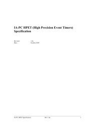
Package Mechanical Specifications3 Package MechanicalSpecificationsThe mobile <strong>Intel</strong> <strong>Pentium</strong> 4 processor <strong>with</strong> <strong>533</strong> <strong>MHz</strong> FSB is packaged in a 478-pin, FC-PGA2package. Components of the package include an integrated heat spreader (IHS), processor die, andthe substrate which is the pin carrier. Different views of the package are shown in Figure 7 throughFigure 12. Package dimensions are shown in Table 17.Note: For Figure 7 through Figure 12, the following notes apply:1. Unless otherwise specified, the following drawings are dimensioned in millimeters.2. Figures and drawings labeled as “Reference Dimensions” are provided for informational purposes only.Reference dimensions are extracted from the mechanical design database and are nominal dimensions <strong>with</strong>no tolerance information applied. Reference dimensions are NOT checked as part of the processormanufacturing process. Unless noted as such, dimensions in parentheses <strong>with</strong>out tolerances are referencedimensions.3. Drawings are not to scale.Note:The drawing below is not to scale and is for reference only. The socket and system board aresupplied as a reference only.Figure 7. Exploded View of <strong>Processor</strong> Components on a System BoardHeat Spreader31 mmSubstrate3.5mm2.0mm35mm square478 pinsSystem boardFC-PGA2Socket<strong>Mobile</strong> <strong>Intel</strong> ® <strong>Pentium</strong> ® 4 <strong>Processor</strong> <strong>with</strong> <strong>533</strong> <strong>MHz</strong> System <strong>Bus</strong> Datasheet 35
Package Mechanical SpecificationsFigure 8. <strong>Processor</strong> Package36 <strong>Mobile</strong> <strong>Intel</strong> ® <strong>Pentium</strong> ® 4 <strong>Processor</strong> <strong>with</strong> <strong>533</strong> <strong>MHz</strong> System <strong>Bus</strong> Datasheet
Package Mechanical SpecificationsTable 17. Description Table for <strong>Processor</strong> DimensionsCode LetterDimension (mm)Min Nominal MaxNotesA1 2.266 2.378 2.490 Original Package (6 layer)A2 0.980 1.080 1.180 Original Package (6 layer)A1 2.42 2.55 2.67 Equivalent Package (8 layer)A2 1.13 1.20 1.27 Equivalent Package (8 layer)B1 30.800 31.000 31.200B2 30.800 31.000 31.200C1 33.000 Includes Placement ToleranceC2 33.000 Includes Placement ToleranceD 34.900 35.000 35.100D1 31.500 31.750 32.000G1 13.970 Keep-In Zone DimensionG2 13.970 Keep-In Zone DimensionG3 1.250 Keep-In Zone DimensionH 1.270L 1.950 2.030 2.110P 0.280 0.305 0.330PIN TP 0.254 Diametric True Position (Pin-to-Pin)IHS Flatness 0.05Figure 9. Cross-Section and Keep-inFCPGA 2IHSSubstrateSocket must allow clearancefor pin shoulders and mateflush <strong>with</strong> this surface13.97mmComponent Keepin1.25mm<strong>Mobile</strong> <strong>Intel</strong> ® <strong>Pentium</strong> ® 4 <strong>Processor</strong> <strong>with</strong> <strong>533</strong> <strong>MHz</strong> System <strong>Bus</strong> Datasheet 37
Package Mechanical SpecificationsFigure 10. <strong>Processor</strong> Pin DetailØ 0.65 MAXPINHEAD DIAMETERØ 0.305±0.025Ø 1.032 MAXKEEP OUT ZONE0.3 MAXSOLDER FILLET HEIGHTALL DIMENSIONS ARE IN MILIMETERS2.03±0.08NOTES:1. Pin plating consists of 0.2 micrometers Au over 2.0 micrometer Ni.2. 0.254 mm diametric true position, pin to pin.Figure 11. IHS Flatness SpecificationIHSSUBSTRATENOTES:1. Flatness is specific as overall, not per unit of length.2. All dimensions are in millimeters.38 <strong>Mobile</strong> <strong>Intel</strong> ® <strong>Pentium</strong> ® 4 <strong>Processor</strong> <strong>with</strong> <strong>533</strong> <strong>MHz</strong> System <strong>Bus</strong> Datasheet
Package Mechanical SpecificationsFigure 12. FC-PGA2 Package - Bottom View14 (K3)AFAEADACABAAYWVUTRPNMLKJHGFEDCBA14 (K3)25X 1.27(e)1235 7 9 11 13 15 17 19 21 23 254 6 8 10 12 14 16 18 20 22 24 2625X 1.27(e)NOTE: All dimensions in millimeters. Values shown are for reference only.The mobile <strong>Intel</strong> <strong>Pentium</strong> 4 processor <strong>with</strong> <strong>533</strong> <strong>MHz</strong> FSB may contain pin side capacitors mountedto the processor package.<strong>Mobile</strong> <strong>Intel</strong> ® <strong>Pentium</strong> ® 4 <strong>Processor</strong> <strong>with</strong> <strong>533</strong> <strong>MHz</strong> System <strong>Bus</strong> Datasheet 39
Package Mechanical Specifications3.1 Package Load SpecificationsTable 18 provides dynamic and static load specifications for the processor IHS. These mechanicalload limits should not be exceeded during heatsink assembly, mechanical stress testing, or standarddrop and shipping conditions. The heatsink attach solutions must not induce continuous stress ontothe processor <strong>with</strong> the exception of a uniform load to maintain the heat sink-to-processor thermalinterface contact. It is not recommended to use any portion of the processor substrate as amechanical reference or load bearing surface for thermal solutions.Table 18. Package Dynamic and Static Load SpecificationsParameter Max Unit NotesStatic 100 lbf 1, 2Dynamic 200 lbf 1, 3NOTES:1. This specification applies to a uniform compressive load.2. This is the maximum static force that can be applied by the heatsink and clip to maintain the heatsink andprocessor interface.3. Dynamic loading specifications are defined assuming a maximum duration of 11 ms and 200 lbf is achievedby superimposing a 100-lbf dynamic load (1 lbm at 50 g) on the static compressive load.3.2 <strong>Processor</strong> Insertion SpecificationsThe mobile <strong>Intel</strong> <strong>Pentium</strong> 4 processor <strong>with</strong> <strong>533</strong> <strong>MHz</strong> FSB can be inserted and removed 15 timesfrom a mPGA478B socket meeting the <strong>Intel</strong> <strong>Pentium</strong> 4 processor 478-Pin (mPGA478B) SocketDesign Guidelines document.3.3 <strong>Processor</strong> Mass SpecificationsTable 19 specifies the processor’s mass. This includes all components which make up the entireprocessor product.Table 19. <strong>Processor</strong> Mass<strong>Processor</strong><strong>Intel</strong> <strong>Pentium</strong> 4 processor <strong>with</strong> 512-kB L2 Cache on0.13 micron processMass (grams)1940 <strong>Mobile</strong> <strong>Intel</strong> ® <strong>Pentium</strong> ® 4 <strong>Processor</strong> <strong>with</strong> <strong>533</strong> <strong>MHz</strong> System <strong>Bus</strong> Datasheet
Package Mechanical Specifications3.4 <strong>Processor</strong> MaterialsThe mobile <strong>Intel</strong> <strong>Pentium</strong> 4 processor <strong>with</strong> <strong>533</strong> <strong>MHz</strong> FSB is assembled from several components.The basic material properties are described in Table 22.Table 20. <strong>Processor</strong> Material PropertiesComponentIntegrated Heat SpreaderSubstrateSubstrate pinsMaterialNickel over copperFiber-reinforced resinGold over nickel3.5 <strong>Processor</strong> MarkingsThe following section details the processor top-side markings and is provided to aid in theidentification of the mobile <strong>Intel</strong> <strong>Pentium</strong> 4 processor <strong>with</strong> <strong>533</strong> <strong>MHz</strong> FSB.Figure 13. <strong>Processor</strong> MarkingsS-Spec/Country of AssyS-Spec/Country of AssyFPO - Serial#FPO - Serial#2-D Matrix Mark2-D Matrix MarkINTEL m © ‘02PENTIUM ® 4TBD2 A GHZ/512/<strong>533</strong>SYYYY XXXXXXFFFFFFFF - NNNNFrequency/Cache/<strong>Bus</strong>Frequency/Cache/Bu3.6 <strong>Processor</strong> Pin-OutFigure 14 shows the top view pinout of the mobile <strong>Intel</strong> <strong>Pentium</strong> 4 processor <strong>with</strong> <strong>533</strong> <strong>MHz</strong> FSB.<strong>Mobile</strong> <strong>Intel</strong> ® <strong>Pentium</strong> ® 4 <strong>Processor</strong> <strong>with</strong> <strong>533</strong> <strong>MHz</strong> System <strong>Bus</strong> Datasheet 41
Package Mechanical SpecificationsFigure 14. The Coordinates of the <strong>Processor</strong> Pins as Viewed From the Top of the Package.1 2 3 4 5 6 7 8 9 10 11 12 13 14 15 16 17 18 19 20 21 22 23 24 25 26ABCDEFGHJKLMNPRTUVWYAAABACADAEAFTHERMTRIP#VSSIGNNE# THRMDAVSSSENSEVCCSENSEVSS SMI# FERR#/PBE#GHI# NC VCC VSS VCC VSS VCC VSS VCC VSS VCC VSS VCC VSS VCC VSS NC D#[2] VSS D#[3] VSSVCC VSS VCC VSS VCC VSS VCC VSS VCC VSS VCC VSS VCC VSS D#[0] D#[1] VSS D#[6] D#[9] VSSTDI VSS PROCHOT# THRMDC VSS A20M# VSS VCC VSS VCC VSS VCC VSS VCC VSS VCC VSS VCC VSS VCC D#[4] VSS D#[7] D#[8] VSS D#[12]LINT0 BPRI# VSS TCK TDO VSS VCC VSS VCC VSS VCC VSS VCC VSS VCC VSS VCC VSS VCC VSS VSS D#[5] D#[13] VSS D#[15] D#[23]VSS DEFER# HITM# VSS LINT1 TRST# VSS VCC VSS VCC VSS VCC VSS VCC VSS VCC VSS VCC VSS VCC DBI#[0]RS#[0] VSS HIT# RS#[2] VSS GTLREF TMS VSS VCC VSS VCC VSS VCC VSS VCC VSS VCC VSS VCC GTLREF DSTBP#[0]DSTBN#[0] VSS D#[17] D#[21] VSSVSS D#[19] D#[20] VSS D#[22]ADS# BNR# VSS LOCK# RS#[1] VSS VSS D#[10] D#[18] VSS DBI#[1] D#[25]VSS DRDY# REQ#[4] VSS DBSY# BR0# D#[11] D#[16] VSS D#[26] D#[31] VSSREQ#[0] VSS REQ#[3]REQ#[2] VSS TRDY# D#[14] VSS DSTBP#[1]A#[6] A#[3] VSS A#[4] REQ#[1] VSS VSS DSTBN#[1]D#[29] VSS DP#[0]D#[30] VSS DP#[1] DP#[2]VSS A#[9] A#[7] VSS ADSTB#[0] A#[5] D#[24] D#[28] VSS COMP[0] DP#[3] VSSA#[13]VSS A#[10] A#[11] VSS A#[8] D#[27] VSS D#[32] D#[35] VSS D#[37]A#[12] A#[14] VSS A#[15] A#[16] VSS VSS D#[33] D#[36] VSS D#[39] D#[38]COMP[1] VSS A#[19] A#[20] VSS A#[24] D#[34] VSS DSTBP#[2]A#[28] D#[40] DSTBN#VSS A#[18] A#[21] VSS ADSTB#[1][2]D#[41] VSS DBI#[2]VSS D#[43] D#[42] VSSA#[17] A#[22] VSS A#[26] A#[30] VSS VSS D#[46] D#[47] VSS D#[45] D#[44]A#[23] VSS A#[25] A#[31] VSS TESTHI8D#[52] VSS D#[50] D#[49] VSS D#[48]VSS A#[27] A#[32] VSS AP#[1] MCERR# DBI#[3] D#[53] VSS D#[54] D#[51] VSSTESTHIA#[29] A#[33] VSS9A#[34] VSS TESTHI10STPCLK#TOP VIEWINIT# VSS VSS DSTBN#[3] DSTBP#[3]VSS D#[57] D#[55]VSS BPM#[3] D#[60] VSS D#[58] D#[59] VSS D#[56]VSS TESTHI1 BINIT# VSS BPM#[4] GTLREF VSS VCC VSS VCC VSS VCC VSS VCC VSS VCC VSS VCC VSS ITPCLKOUT GTLREF[0]D#[62] VSS D#[63] D#[61] VSSA#[35] RSP# VSS BPM#[5] BPM#[1] VSS VCC VSS VCC VSS VCC VSS VCC VSS VCC VSS VCC VSS VCC VSS VSS ITPCLKOU PWRGOODVSS RESET# SLP#T[1]AP#[0] VSS IERR# BPM#[2] VSS BPM#[0] VSS VCC VSS VCC VSS VCC VSS VCC VSS VCC VSS VCC VSS TESTHI3 TESTHI2 VSS TESTHI5 TESTHI4 VSS ITP_CLK0VSS NC NC VSS BSEL1 BSEL0 VCC VSS VCC VSS VCC VSS VCC VSS VCC VSS VCC VSS VCC VCCA VSS VSSA VSS TESTHI0VID4 VID3 VID2 VID1 VID0 VCC VSS VCC VSS VCC VSS VCC VSS VCC VSS VCC VSS VCC VSS VCC NC VSS VCCIO_PLLDPSLP# ITP_CLK1VSS DBR# VSSVSS VCC NC VCCVID VCC VSS VCC VSS VCC VSS VCC VSS VCC VSS VCC VSS VCC VSS VCC VSS VCC BCLK[0] BCLK[1] NC NCSKTOCC#ABCDEFGHJKLMNPRTUVWYAAABACADAEAF1 2 3 4 5 6 7 8 9 10 11 12 13 14 15 16 17 18 19 20 21 22 23 24 25 26VSS VCC Other42 <strong>Mobile</strong> <strong>Intel</strong> ® <strong>Pentium</strong> ® 4 <strong>Processor</strong> <strong>with</strong> <strong>533</strong> <strong>MHz</strong> System <strong>Bus</strong> Datasheet
Pin Listing and Signal Definitions4 Pin Listing and Signal Definitions4.1 <strong>Mobile</strong> <strong>Intel</strong> <strong>Pentium</strong> 4 <strong>Processor</strong> Pin AssignmentsSection 4.1 contains the preliminary pin list for the mobile <strong>Intel</strong> <strong>Pentium</strong> 4 processor <strong>with</strong> <strong>533</strong> <strong>MHz</strong>FSB in Table 21 and Table 22. Table 21 is a listing of all processor pins ordered alphabetically by pinname. Table 22 is also a listing of all processor pins but ordered by pin number.<strong>Mobile</strong> <strong>Intel</strong> ® <strong>Pentium</strong> ® 4 <strong>Processor</strong> <strong>with</strong> <strong>533</strong> <strong>MHz</strong> System <strong>Bus</strong> Datasheet 43
Pin Listing and Signal DefinitionsTable 21.Pin Listing by Pin NameTable 21.Pin NamePin Listing by Pin NamePinNumberSignal BufferTypeDirectionA#[03] K2 Source Synch Input/OutputA#[04] K4 Source Synch Input/OutputA#[05] L6 Source Synch Input/OutputA#[06] K1 Source Synch Input/OutputA#[07] L3 Source Synch Input/OutputA#[08] M6 Source Synch Input/OutputA#[09] L2 Source Synch Input/OutputA#[10] M3 Source Synch Input/OutputA#[11] M4 Source Synch Input/OutputA#[12] N1 Source Synch Input/OutputA#[13] M1 Source Synch Input/OutputA#[14] N2 Source Synch Input/OutputA#[15] N4 Source Synch Input/OutputA#[16] N5 Source Synch Input/OutputA#[17] T1 Source Synch Input/OutputA#[18] R2 Source Synch Input/OutputA#[19] P3 Source Synch Input/OutputA#[20] P4 Source Synch Input/OutputA#[21] R3 Source Synch Input/OutputA#[22] T2 Source Synch Input/OutputA#[23] U1 Source Synch Input/OutputA#[24] P6 Source Synch Input/OutputA#[25] U3 Source Synch Input/OutputA#[26] T4 Source Synch Input/OutputA#[27] V2 Source Synch Input/OutputA#[28] R6 Source Synch Input/OutputA#[29] W1 Source Synch Input/OutputA#[30] T5 Source Synch Input/OutputA#[31] U4 Source Synch Input/OutputA#[32] V3 Source Synch Input/OutputA#[33] W2 Source Synch Input/OutputA#[34] Y1 Source Synch Input/OutputA#[35] AB1 Source Synch Input/OutputA20M# C6 Asynch GTL+ InputADS# G1 Common Clock Input/OutputADSTB#[0] L5 Source Synch Input/OutputADSTB#[1] R5 Source Synch Input/OutputPin NamePinNumberSignal BufferTypeAP#[0] AC1 Common Clock Input/OutputAP#[1] V5 Common Clock Input/OutputBCLK[0] AF22 <strong>Bus</strong> Clock InputBCLK[1] AF23 <strong>Bus</strong> Clock InputBINIT# AA3 Common Clock Input/OutputBNR# G2 Common Clock Input/OutputBPM#[0] AC6 Common Clock Input/OutputBPM#[1] AB5 Common Clock Input/OutputBPM#[2] AC4 Common Clock Input/OutputBPM#[3] Y6 Common Clock Input/OutputBPM#[4] AA5 Common Clock Input/OutputBPM#[5] AB4 Common Clock Input/OutputBPRI# D2 Common Clock InputBR0# H6 Common Clock Input/OutputBSEL0 AD6 Power/Other OutputBSEL1 AD5 Power/Other OutputDirectionCOMP[0] L24 Power/Other Input/OutputCOMP[1] P1 Power/Other Input/OutputD#[0] B21 Source Synch Input/OutputD#[01] B22 Source Synch Input/OutputD#[02] A23 Source Synch Input/OutputD#[03] A25 Source Synch Input/OutputD#[04] C21 Source Synch Input/OutputD#[05] D22 Source Synch Input/OutputD#[06] B24 Source Synch Input/OutputD#[07] C23 Source Synch Input/OutputD#[08] C24 Source Synch Input/OutputD#[09] B25 Source Synch Input/OutputD#[10] G22 Source Synch Input/OutputD#[11] H21 Source Synch Input/OutputD#[12] C26 Source Synch Input/OutputD#[13] D23 Source Synch Input/OutputD#[14] J21 Source Synch Input/OutputD#[15] D25 Source Synch Input/OutputD#[16] H22 Source Synch Input/OutputD#[17] E24 Source Synch Input/OutputD#[18] G23 Source Synch Input/OutputD#[19] F23 Source Synch Input/OutputD#[20] F24 Source Synch Input/Output44 <strong>Mobile</strong> <strong>Intel</strong> ® <strong>Pentium</strong> ® 4 <strong>Processor</strong> <strong>with</strong> <strong>533</strong> <strong>MHz</strong> System <strong>Bus</strong> Datasheet
Pin Listing and Signal DefinitionsTable 21.Pin Listing by Pin NameTable 21.Pin Listing by Pin NamePin NamePinNumberSignal BufferTypeDirectionPin NamePinNumberSignal BufferTypeDirectionD#[21] E25 Source Synch Input/OutputD#[22] F26 Source Synch Input/OutputD#[23] D26 Source Synch Input/OutputD#[24] L21 Source Synch Input/OutputD#[25] G26 Source Synch Input/OutputD#[26] H24 Source Synch Input/OutputD#[27] M21 Source Synch Input/OutputD#[28] L22 Source Synch Input/OutputD#[29] J24 Source Synch Input/OutputD#[30] K23 Source Synch Input/OutputD#[31] H25 Source Synch Input/OutputD#[32] M23 Source Synch Input/OutputD#[33] N22 Source Synch Input/OutputD#[34] P21 Source Synch Input/OutputD#[35] M24 Source Synch Input/OutputD#[36] N23 Source Synch Input/OutputD#[37] M26 Source Synch Input/OutputD#[38] N26 Source Synch Input/OutputD#[39] N25 Source Synch Input/OutputD#[40] R21 Source Synch Input/OutputD#[41] P24 Source Synch Input/OutputD#[42] R25 Source Synch Input/OutputD#[43] R24 Source Synch Input/OutputD#[44] T26 Source Synch Input/OutputD#[45] T25 Source Synch Input/OutputD#[46] T22 Source Synch Input/OutputD#[47] T23 Source Synch Input/OutputD#[48] U26 Source Synch Input/OutputD#[49] U24 Source Synch Input/OutputD#[50] U23 Source Synch Input/OutputD#[51] V25 Source Synch Input/OutputD#[52] U21 Source Synch Input/OutputD#[53] V22 Source Synch Input/OutputD#[54] V24 Source Synch Input/OutputD#[55] W26 Source Synch Input/OutputD#[56] Y26 Source Synch Input/OutputD#[57] W25 Source Synch Input/OutputD#[58] Y23 Source Synch Input/OutputD#[59] Y24 Source Synch Input/OutputD#[60] Y21 Source Synch Input/OutputD#[61] AA25 Source Synch Input/OutputD#[62] AA22 Source Synch Input/OutputD#[63] AA24 Source Synch Input/OutputDBI#[0] E21 Source Synch Input/OutputDBI#[1] G25 Source Synch Input/OutputDBI#[2] P26 Source Synch Input/OutputDBI#[3] V21 Source Synch Input/OutputDBR# AE25 Power/Other OutputDBSY# H5 Common Clock Input/OutputDEFER# E2 Common Clock InputDP#[0] J26 Common Clock Input/OutputDP#[1] K25 Common Clock Input/OutputDP#[2] K26 Common Clock Input/OutputDP#[3] L25 Common Clock Input/OutputDPSLP# AD25 Asynch GTL+ InputDRDY# H2 Common Clock Input/OutputDSTBN#[0] E22 Source Synch Input/OutputDSTBN#[1] K22 Source Synch Input/OutputDSTBN#[2] R22 Source Synch Input/OutputDSTBN#[3] W22 Source Synch Input/OutputDSTBP#[0] F21 Source Synch Input/OutputDSTBP#[1] J23 Source Synch Input/OutputDSTBP#[2] P23 Source Synch Input/OutputDSTBP#[3] W23 Source Synch Input/OutputFERR#/PBE# B6 Asynch AGL+ OutputGHI# A6 Asynch GTL+ InputGTLREF AA21 Power/Other InputGTLREF AA6 Power/Other InputGTLREF F20 Power/Other InputGTLREF F6 Power/Other InputHIT# F3 Common Clock Input/OutputHITM# E3 Common Clock Input/OutputIERR# AC3 Common Clock OutputIGNNE# B2 Asynch GTL+ InputIMPSEL AE26 Power/Other InputINIT# W5 Asynch GTL+ InputITPCLKOUT[0] AA20 Power/Other OutputITPCLKOUT[1] AB22 Power/Other Output<strong>Mobile</strong> <strong>Intel</strong> ® <strong>Pentium</strong> ® 4 <strong>Processor</strong> <strong>with</strong> <strong>533</strong> <strong>MHz</strong> System <strong>Bus</strong> Datasheet 45
Pin Listing and Signal DefinitionsTable 21.Pin Listing by Pin NameTable 21.Pin Listing by Pin NamePin NamePinNumberSignal BufferTypeDirectionPin NamePinNumberSignal BufferTypeDirectionITP_CLK0 AC26 TAP inputITP_CLK1 AD26 TAP inputLINT0 D1 Asynch GTL+ InputLINT1 E5 Asynch GTL+ InputLOCK# G4 Common Clock Input/OutputMCERR# V6 Common Clock Input/OutputNCA22NCA7NCAD2NCAD3NCAE21NCAF3NCAF24NCAF25PROCHOT# C3 Asynch GTL+ Input/OutputPWRGOOD AB23 Power/Other InputREQ#[0] J1 Source Synch Input/OutputREQ#[1] K5 Source Synch Input/OutputREQ#[2] J4 Source Synch Input/OutputREQ#[3] J3 Source Synch Input/OutputREQ#[4] H3 Source Synch Input/OutputRESET# AB25 Common Clock InputRS#[0] F1 Common Clock InputRS#[1] G5 Common Clock InputRS#[2] F4 Common Clock InputRSP# AB2 Common Clock InputSKTOCC# AF26 Power/Other OutputSLP# AB26 Asynch GTL+ InputSMI# B5 Asynch GTL+ InputSTPCLK# Y4 Asynch GTL+ InputTCK D4 TAP InputTDI C1 TAP InputTDO D5 TAP OutputTESTHI0 AD24 Power/Other InputTESTHI1 AA2 Power/Other InputTESTHI2 AC21 Power/Other InputTESTHI3 AC20 Power/Other InputTESTHI4 AC24 Power/Other InputTESTHI5 AC23 Power/Other InputTESTHI8 U6 Power/Other InputTESTHI9 W4 Power/Other InputTESTHI10 Y3 Power/Other InputTHERMDA B3 Power/OtherTHERMDC C4 Power/OtherTHERMTRIP# A2 Asynch GTL+ OutputTMS F7 TAP InputTRDY# J6 Common Clock InputTRST# E6 TAP InputVCC A10 Power/OtherVCC A12 Power/OtherVCC A14 Power/OtherVCC A16 Power/OtherVCC A18 Power/OtherVCC A20 Power/OtherVCC A8 Power/OtherVCC AA10 Power/OtherVCC AA12 Power/OtherVCC AA14 Power/OtherVCC AA16 Power/OtherVCC AA18 Power/OtherVCC AA8 Power/OtherVCC AB11 Power/OtherVCC AB13 Power/OtherVCC AB15 Power/OtherVCC AB17 Power/OtherVCC AB19 Power/OtherVCC AB7 Power/OtherVCC AB9 Power/OtherVCC AC10 Power/OtherVCC AC12 Power/OtherVCC AC14 Power/OtherVCC AC16 Power/OtherVCC AC18 Power/OtherVCC AC8 Power/OtherVCC AD11 Power/OtherVCC AD13 Power/OtherVCC AD15 Power/OtherVCC AD17 Power/Other46 <strong>Mobile</strong> <strong>Intel</strong> ® <strong>Pentium</strong> ® 4 <strong>Processor</strong> <strong>with</strong> <strong>533</strong> <strong>MHz</strong> System <strong>Bus</strong> Datasheet
Pin Listing and Signal DefinitionsTable 21.Pin Listing by Pin NameTable 21.Pin Listing by Pin NamePin NamePinNumberSignal BufferTypeDirectionPin NamePinNumberSignal BufferTypeDirectionVCC AD19 Power/OtherVCC AD7 Power/OtherVCC AD9 Power/OtherVCC AE10 Power/OtherVCC AE12 Power/OtherVCC AE14 Power/OtherVCC AE16 Power/OtherVCC AE18 Power/OtherVCC AE20 Power/OtherVCC AE6 Power/OtherVCC AE8 Power/OtherVCC AF11 Power/OtherVCC AF13 Power/OtherVCC AF15 Power/OtherVCC AF17 Power/OtherVCC AF19 Power/OtherVCC AF2 Power/OtherVCC AF21 Power/OtherVCC AF5 Power/OtherVCC AF7 Power/OtherVCC AF9 Power/OtherVCC B11 Power/OtherVCC B13 Power/OtherVCC B15 Power/OtherVCC B17 Power/OtherVCC B19 Power/OtherVCC B7 Power/OtherVCC B9 Power/OtherVCC C10 Power/OtherVCC C12 Power/OtherVCC C14 Power/OtherVCC C16 Power/OtherVCC C18 Power/OtherVCC C20 Power/OtherVCC C8 Power/OtherVCC D11 Power/OtherVCC D13 Power/OtherVCC D15 Power/OtherVCC D17 Power/OtherVCC D19 Power/OtherVCC D7 Power/OtherVCC D9 Power/OtherVCC E10 Power/OtherVCC E12 Power/OtherVCC E14 Power/OtherVCC E16 Power/OtherVCC E18 Power/OtherVCC E20 Power/OtherVCC E8 Power/OtherVCC F11 Power/OtherVCC F13 Power/OtherVCC F15 Power/OtherVCC F17 Power/OtherVCC F19 Power/OtherVCC F9 Power/OtherVCCA AD20 Power/OtherVCCIOPLL AE23 Power/OtherVCCSENSE A5 Power/Other OutputVCCVID AF4 Power/Other InputVID0 AE5 Power/Other OutputVID1 AE4 Power/Other OutputVID2 AE3 Power/Other OutputVID3 AE2 Power/Other OutputVID4 AE1 Power/Other OutputVSS A11 Power/OtherVSS A13 Power/OtherVSS A15 Power/OtherVSS A17 Power/OtherVSS A19 Power/OtherVSS A21 Power/OtherVSS A24 Power/OtherVSS A26 Power/OtherVSS A3 Power/OtherVSS A9 Power/OtherVSS AA1 Power/OtherVSS AA11 Power/OtherVSS AA13 Power/OtherVSS AA15 Power/Other<strong>Mobile</strong> <strong>Intel</strong> ® <strong>Pentium</strong> ® 4 <strong>Processor</strong> <strong>with</strong> <strong>533</strong> <strong>MHz</strong> System <strong>Bus</strong> Datasheet 47
Pin Listing and Signal DefinitionsTable 21.Pin Listing by Pin NameTable 21.Pin Listing by Pin NamePin NamePinNumberSignal BufferTypeDirectionPin NamePinNumberSignal BufferTypeDirectionVSS AA17 Power/OtherVSS AA19 Power/OtherVSS AA23 Power/OtherVSS AA26 Power/OtherVSS AA4 Power/OtherVSS AA7 Power/OtherVSS AA9 Power/OtherVSS AB10 Power/OtherVSS AB12 Power/OtherVSS AB14 Power/OtherVSS AB16 Power/OtherVSS AB18 Power/OtherVSS AB20 Power/OtherVSS AB21 Power/OtherVSS AB24 Power/OtherVSS AB3 Power/OtherVSS AB6 Power/OtherVSS AB8 Power/OtherVSS AC11 Power/OtherVSS AC13 Power/OtherVSS AC15 Power/OtherVSS AC17 Power/OtherVSS AC19 Power/OtherVSS AC2 Power/OtherVSS AC22 Power/OtherVSS AC25 Power/OtherVSS AC5 Power/OtherVSS AC7 Power/OtherVSS AC9 Power/OtherVSS AD1 Power/OtherVSS AD10 Power/OtherVSS AD12 Power/OtherVSS AD14 Power/OtherVSS AD16 Power/OtherVSS AD18 Power/OtherVSS AD21 Power/OtherVSS AD23 Power/OtherVSS AD4 Power/OtherVSS AD8 Power/OtherVSS AE11 Power/OtherVSS AE13 Power/OtherVSS AE15 Power/OtherVSS AE17 Power/OtherVSS AE19 Power/OtherVSS AE22 Power/OtherVSS AE24 Power/OtherVSS AE7 Power/OtherVSS AE9 Power/OtherVSS AF1 Power/OtherVSS AF10 Power/OtherVSS AF12 Power/OtherVSS AF14 Power/OtherVSS AF16 Power/OtherVSS AF18 Power/OtherVSS AF20 Power/OtherVSS AF6 Power/OtherVSS AF8 Power/OtherVSS B10 Power/OtherVSS B12 Power/OtherVSS B14 Power/OtherVSS B16 Power/OtherVSS B18 Power/OtherVSS B20 Power/OtherVSS B23 Power/OtherVSS B26 Power/OtherVSS B4 Power/OtherVSS B8 Power/OtherVSS C11 Power/OtherVSS C13 Power/OtherVSS C15 Power/OtherVSS C17 Power/OtherVSS C19 Power/OtherVSS C2 Power/OtherVSS C22 Power/OtherVSS C25 Power/OtherVSS C5 Power/OtherVSS C7 Power/OtherVSS C9 Power/Other48 <strong>Mobile</strong> <strong>Intel</strong> ® <strong>Pentium</strong> ® 4 <strong>Processor</strong> <strong>with</strong> <strong>533</strong> <strong>MHz</strong> System <strong>Bus</strong> Datasheet
Pin Listing and Signal DefinitionsTable 21.Pin Listing by Pin NameTable 21.Pin Listing by Pin NamePin NamePinNumberSignal BufferTypeDirectionPin NamePinNumberSignal BufferTypeDirectionVSS D10 Power/OtherVSS D12 Power/OtherVSS D14 Power/OtherVSS D16 Power/OtherVSS D18 Power/OtherVSS D20 Power/OtherVSS D21 Power/OtherVSS D24 Power/OtherVSS D3 Power/OtherVSS D6 Power/OtherVSS D8 Power/OtherVSS E1 Power/OtherVSS E11 Power/OtherVSS E13 Power/OtherVSS E15 Power/OtherVSS E17 Power/OtherVSS E19 Power/OtherVSS E23 Power/OtherVSS E26 Power/OtherVSS E4 Power/OtherVSS E7 Power/OtherVSS E9 Power/OtherVSS F10 Power/OtherVSS F12 Power/OtherVSS F14 Power/OtherVSS F16 Power/OtherVSS F18 Power/OtherVSS F2 Power/OtherVSS F22 Power/OtherVSS F25 Power/OtherVSS F5 Power/OtherVSS F8 Power/OtherVSS G21 Power/OtherVSS G24 Power/OtherVSS G3 Power/OtherVSS G6 Power/OtherVSS H1 Power/OtherVSS H23 Power/OtherVSS H26 Power/OtherVSS H4 Power/OtherVSS J2 Power/OtherVSS J22 Power/OtherVSS J25 Power/OtherVSS J5 Power/OtherVSS K21 Power/OtherVSS K24 Power/OtherVSS K3 Power/OtherVSS K6 Power/OtherVSS L1 Power/OtherVSS L23 Power/OtherVSS L26 Power/OtherVSS L4 Power/OtherVSS M2 Power/OtherVSS M22 Power/OtherVSS M25 Power/OtherVSS M5 Power/OtherVSS N21 Power/OtherVSS N24 Power/OtherVSS N3 Power/OtherVSS N6 Power/OtherVSS P2 Power/OtherVSS P22 Power/OtherVSS P25 Power/OtherVSS P5 Power/OtherVSS R1 Power/OtherVSS R23 Power/OtherVSS R26 Power/OtherVSS R4 Power/OtherVSS T21 Power/OtherVSS T24 Power/OtherVSS T3 Power/OtherVSS T6 Power/OtherVSS U2 Power/OtherVSS U22 Power/OtherVSS U25 Power/OtherVSS U5 Power/OtherVSS V1 Power/OtherVSS V23 Power/Other<strong>Mobile</strong> <strong>Intel</strong> ® <strong>Pentium</strong> ® 4 <strong>Processor</strong> <strong>with</strong> <strong>533</strong> <strong>MHz</strong> System <strong>Bus</strong> Datasheet 49
Pin Listing and Signal DefinitionsTable 21.Pin Listing by Pin NameTable 22. Pin Listing by Pin NumberPin NamePinNumberSignal BufferTypeDirectionPinNumberPin NameSignal BufferTypeDirectionVSS V26 Power/OtherVSS V4 Power/OtherVSS W21 Power/OtherVSS W24 Power/OtherVSS W3 Power/OtherVSS W6 Power/OtherVSS Y2 Power/OtherVSS Y22 Power/OtherVSS Y25 Power/OtherVSS Y5 Power/OtherVSSA AD22 Power/OtherVSSSENSE A4 Power/Other OutputTable 22. Pin Listing by Pin NumberPinNumberPin NameSignal BufferTypeA2 THERMTRIP# Asynch GTL+ OutputA3 VSS Power/OtherA4 VSSSENSE Power/Other OutputA5 VCCSENSE Power/Other OutputA6 GHI# Asynch GTL+ InputA7NCA8 VCC Power/OtherA9 VSS Power/OtherA10 VCC Power/OtherA11 VSS Power/OtherA12 VCC Power/OtherA13 VSS Power/OtherA14 VCC Power/OtherA15 VSS Power/OtherA16 VCC Power/OtherA17 VSS Power/OtherA18 VCC Power/OtherA19 VSS Power/OtherA20 VCC Power/OtherA21 VSS Power/OtherA22NCDirectionA23 D#[02] Source Synch Input/OutputA24 VSS Power/OtherA25 D#[03] Source Synch Input/OutputA26 VSS Power/OtherAA1 VSS Power/OtherAA2 TESTHI1 Power/Other InputAA3 BINIT# Common Clock Input/OutputAA4 VSS Power/OtherAA5 BPM#[4] Common Clock Input/OutputAA6 GTLREF Power/Other InputAA7 VSS Power/OtherAA8 VCC Power/OtherAA9 VSS Power/OtherAA10 VCC Power/OtherAA11 VSS Power/OtherAA12 VCC Power/OtherAA13 VSS Power/OtherAA14 VCC Power/OtherAA15 VSS Power/OtherAA16 VCC Power/OtherAA17 VSS Power/OtherAA18 VCC Power/OtherAA19 VSS Power/OtherAA20ITPCLKOUT[0]Power/OtherOutputAA21 GTLREF Power/Other InputAA22 D#[62] Source Synch Input/OutputAA23 VSS Power/OtherAA24 D#[63] Source Synch Input/OutputAA25 D#[61] Source Synch Input/OutputAA26 VSS Power/OtherAB1 A#[35] Source Synch Input/OutputAB2 RSP# Common Clock InputAB3 VSS Power/OtherAB4 BPM#[5] Common Clock Input/OutputAB5 BPM#[1] Common Clock Input/OutputAB6 VSS Power/OtherAB7 VCC Power/OtherAB8 VSS Power/OtherAB9 VCC Power/OtherAB10 VSS Power/Other50 <strong>Mobile</strong> <strong>Intel</strong> ® <strong>Pentium</strong> ® 4 <strong>Processor</strong> <strong>with</strong> <strong>533</strong> <strong>MHz</strong> System <strong>Bus</strong> Datasheet
Pin Listing and Signal DefinitionsTable 22. Pin Listing by Pin NumberTable 22. Pin Listing by Pin NumberPinNumberPin NameSignal BufferTypeDirectionPinNumberPin NameSignal BufferTypeDirectionAB11 VCC Power/OtherAB12 VSS Power/OtherAB13 VCC Power/OtherAB14 VSS Power/OtherAB15 VCC Power/OtherAB16 VSS Power/OtherAB17 VCC Power/OtherAB18 VSS Power/OtherAB19 VCC Power/OtherAB20 VSS Power/OtherAB21 VSS Power/OtherAB22ITPCLKOUT[1]Power/OtherOutputAB23 PWRGOOD Power/Other InputAB24 VSS Power/OtherAB25 RESET# Common Clock InputAB26 SLP# Asynch GTL+ InputAC1 AP#[0] Common Clock Input/OutputAC2 VSS Power/OtherAC3 IERR# Common Clock OutputAC4 BPM#[2] Common Clock Input/OutputAC5 VSS Power/OtherAC6 BPM#[0] Common Clock Input/OutputAC7 VSS Power/OtherAC8 VCC Power/OtherAC9 VSS Power/OtherAC10 VCC Power/OtherAC11 VSS Power/OtherAC12 VCC Power/OtherAC13 VSS Power/OtherAC14 VCC Power/OtherAC15 VSS Power/OtherAC16 VCC Power/OtherAC17 VSS Power/OtherAC18 VCC Power/OtherAC19 VSS Power/OtherAC20 TESTHI3 Power/Other InputAC21 TESTHI2 Power/Other InputAC22 VSS Power/OtherAC23 TESTHI5 Power/Other InputAC24 TESTHI4 Power/Other InputAC25 VSS Power/OtherAC26 ITP_CLK0 TAP inputAD1 VSS Power/OtherAD2 NCAD3 NCAD4 VSS Power/OtherAD5 BSEL1 Power/Other OutputAD6 BSEL0 Power/Other OutputAD7 VCC Power/OtherAD8 VSS Power/OtherAD9 VCC Power/OtherAD10 VSS Power/OtherAD11 VCC Power/OtherAD12 VSS Power/OtherAD13 VCC Power/OtherAD14 VSS Power/OtherAD15 VCC Power/OtherAD16 VSS Power/OtherAD17 VCC Power/OtherAD18 VSS Power/OtherAD19 VCC Power/OtherAD20 VCCA Power/OtherAD21 VSS Power/OtherAD22 VSSA Power/OtherAD23 VSS Power/OtherAD24 TESTHI0 Power/Other InputAD25 DPSLP# Asynch GTL+ InputAD26 ITP_CLK1 TAP inputAE1 VID4 Power/Other OutputAE2 VID3 Power/Other OutputAE3 VID2 Power/Other OutputAE4 VID1 Power/Other OutputAE5 VID0 Power/Other OutputAE6 VCC Power/OtherAE7 VSS Power/OtherAE8 VCC Power/OtherAE9 VSS Power/Other<strong>Mobile</strong> <strong>Intel</strong> ® <strong>Pentium</strong> ® 4 <strong>Processor</strong> <strong>with</strong> <strong>533</strong> <strong>MHz</strong> System <strong>Bus</strong> Datasheet 51
Pin Listing and Signal DefinitionsTable 22. Pin Listing by Pin NumberTable 22. Pin Listing by Pin NumberPinNumberPin NameSignal BufferTypeDirectionPinNumberPin NameSignal BufferTypeDirectionAE10 VCC Power/OtherAE11 VSS Power/OtherAE12 VCC Power/OtherAE13 VSS Power/OtherAE14 VCC Power/OtherAE15 VSS Power/OtherAE16 VCC Power/OtherAE17 VSS Power/OtherAE18 VCC Power/OtherAE19 VSS Power/OtherAE20 VCC Power/OtherAE21 NCAE22 VSS Power/OtherAE23 VCCIOPLL Power/OtherAE24 VSS Power/OtherAE25 DBR# Asynch GTL+ OutputAE26 IMPSEL Power/Other InputAF1 VSS Power/OtherAF2 VCC Power/OtherAF3 NCAF4 VCCVID Power/Other InputAF5 VCC Power/OtherAF6 VSS Power/OtherAF7 VCC Power/OtherAF8 VSS Power/OtherAF9 VCC Power/OtherAF10 VSS Power/OtherAF11 VCC Power/OtherAF12 VSS Power/OtherAF13 VCC Power/OtherAF14 VSS Power/OtherAF15 VCC Power/OtherAF16 VSS Power/OtherAF17 VCC Power/OtherAF18 VSS Power/OtherAF19 VCC Power/OtherAF20 VSS Power/OtherAF21 VCC Power/OtherAF22 BCLK[0] <strong>Bus</strong> Clock InputAF23 BCLK[1] <strong>Bus</strong> Clock InputAF24 NCAF25 NCAF26 SKTOCC# Power/Other OutputB2 IGNNE# Asynch GTL+ InputB3 THERMDA Power/OtherB4 VSS Power/OtherB5 SMI# Asynch GTL+ InputB6 FERR#/PBE# Asynch AGL+ OutputB7 VCC Power/OtherB8 VSS Power/OtherB9 VCC Power/OtherB10 VSS Power/OtherB11 VCC Power/OtherB12 VSS Power/OtherB13 VCC Power/OtherB14 VSS Power/OtherB15 VCC Power/OtherB16 VSS Power/OtherB17 VCC Power/OtherB18 VSS Power/OtherB19 VCC Power/OtherB20 VSS Power/OtherB21 D#[0] Source Synch Input/OutputB22 D#[01] Source Synch Input/OutputB23 VSS Power/OtherB24 D#[06] Source Synch Input/OutputB25 D#[09] Source Synch Input/OutputB26 VSS Power/OtherC1 TDI TAP InputC2 VSS Power/OtherC3 PROCHOT# Asynch GTL+ Input/OutputC4 THERMDC Power/OtherC5 VSS Power/OtherC6 A20M# Asynch GTL+ InputC7 VSS Power/OtherC8 VCC Power/OtherC9 VSS Power/OtherC10 VCC Power/Other52 <strong>Mobile</strong> <strong>Intel</strong> ® <strong>Pentium</strong> ® 4 <strong>Processor</strong> <strong>with</strong> <strong>533</strong> <strong>MHz</strong> System <strong>Bus</strong> Datasheet
Pin Listing and Signal DefinitionsTable 22. Pin Listing by Pin NumberTable 22. Pin Listing by Pin NumberPinNumberPin NameSignal BufferTypeDirectionPinNumberPin NameSignal BufferTypeDirectionC11 VSS Power/OtherC12 VCC Power/OtherC13 VSS Power/OtherC14 VCC Power/OtherC15 VSS Power/OtherC16 VCC Power/OtherC17 VSS Power/OtherC18 VCC Power/OtherC19 VSS Power/OtherC20 VCC Power/OtherC21 D#[04] Source Synch Input/OutputC22 VSS Power/OtherC23 D#[07] Source Synch Input/OutputC24 D#[08] Source Synch Input/OutputC25 VSS Power/OtherC26 D#[12] Source Synch Input/OutputD1 LINT0 Asynch GTL+ InputD2 BPRI# Common Clock InputD3 VSS Power/OtherD4 TCK TAP InputD5 TDO TAP OutputD6 VSS Power/OtherD7 VCC Power/OtherD8 VSS Power/OtherD9 VCC Power/OtherD10 VSS Power/OtherD11 VCC Power/OtherD12 VSS Power/OtherD13 VCC Power/OtherD14 VSS Power/OtherD15 VCC Power/OtherD16 VSS Power/OtherD17 VCC Power/OtherD18 VSS Power/OtherD19 VCC Power/OtherD20 VSS Power/OtherD21 VSS Power/OtherD22 D#[05] Source Synch Input/OutputD23 D#[13] Source Synch Input/OutputD24 VSS Power/OtherD25 D#[15] Source Synch Input/OutputD26 D#[23] Source Synch Input/OutputE1 VSS Power/OtherE2 DEFER# Common Clock InputE3 HITM# Common Clock Input/OutputE4 VSS Power/OtherE5 LINT1 Asynch GTL+ InputE6 TRST# TAP InputE7 VSS Power/OtherE8 VCC Power/OtherE9 VSS Power/OtherE10 VCC Power/OtherE11 VSS Power/OtherE12 VCC Power/OtherE13 VSS Power/OtherE14 VCC Power/OtherE15 VSS Power/OtherE16 VCC Power/OtherE17 VSS Power/OtherE18 VCC Power/OtherE19 VSS Power/OtherE20 VCC Power/OtherE21 DBI#[0] Source Synch Input/OutputE22 DSTBN#[0] Source Synch Input/OutputE23 VSS Power/OtherE24 D#[17] Source Synch Input/OutputE25 D#[21] Source Synch Input/OutputE26 VSS Power/OtherF1 RS#[0] Common Clock InputF2 VSS Power/OtherF3 HIT# Common Clock Input/OutputF4 RS#[2] Common Clock InputF5 VSS Power/OtherF6 GTLREF Power/Other InputF7 TMS TAP InputF8 VSS Power/OtherF9 VCC Power/OtherF10 VSS Power/Other<strong>Mobile</strong> <strong>Intel</strong> ® <strong>Pentium</strong> ® 4 <strong>Processor</strong> <strong>with</strong> <strong>533</strong> <strong>MHz</strong> System <strong>Bus</strong> Datasheet 53
Pin Listing and Signal DefinitionsTable 22. Pin Listing by Pin NumberTable 22. Pin Listing by Pin NumberPinNumberPin NameSignal BufferTypeDirectionPinNumberPin NameSignal BufferTypeDirectionF11 VCC Power/OtherF12 VSS Power/OtherF13 VCC Power/OtherF14 VSS Power/OtherF15 VCC Power/OtherF16 VSS Power/OtherF17 VCC Power/OtherF18 VSS Power/OtherF19 VCC Power/OtherF20 GTLREF Power/Other InputF21 DSTBP#[0] Source Synch Input/OutputF22 VSS Power/OtherF23 D#[19] Source Synch Input/OutputF24 D#[20] Source Synch Input/OutputF25 VSS Power/OtherF26 D#[22] Source Synch Input/OutputG1 ADS# Common Clock Input/OutputG2 BNR# Common Clock Input/OutputG3 VSS Power/OtherG4 LOCK# Common Clock Input/OutputG5 RS#[1] Common Clock InputG6 VSS Power/OtherG21 VSS Power/OtherG22 D#[10] Source Synch Input/OutputG23 D#[18] Source Synch Input/OutputG24 VSS Power/OtherG25 DBI#[1] Source Synch Input/OutputG26 D#[25] Source Synch Input/OutputH1 VSS Power/OtherH2 DRDY# Common Clock Input/OutputH3 REQ#[4] Source Synch Input/OutputH4 VSS Power/OtherH5 DBSY# Common Clock Input/OutputH6 BR0# Common Clock Input/OutputH21 D#[11] Source Synch Input/OutputH22 D#[16] Source Synch Input/OutputH23 VSS Power/OtherH24 D#[26] Source Synch Input/OutputH25 D#[31] Source Synch Input/OutputH26 VSS Power/OtherJ1 REQ#[0] Source Synch Input/OutputJ2 VSS Power/OtherJ3 REQ#[3] Source Synch Input/OutputJ4 REQ#[2] Source Synch Input/OutputJ5 VSS Power/OtherJ6 TRDY# Common Clock InputJ21 D#[14] Source Synch Input/OutputJ22 VSS Power/OtherJ23 DSTBP#[1] Source Synch Input/OutputJ24 D#[29] Source Synch Input/OutputJ25 VSS Power/OtherJ26 DP#[0] Common Clock Input/OutputK1 A#[06] Source Synch Input/OutputK2 A#[03] Source Synch Input/OutputK3 VSS Power/OtherK4 A#[04] Source Synch Input/OutputK5 REQ#[1] Source Synch Input/OutputK6 VSS Power/OtherK21 VSS Power/OtherK22 DSTBN#[1] Source Synch Input/OutputK23 D#[30] Source Synch Input/OutputK24 VSS Power/OtherK25 DP#[1] Common Clock Input/OutputK26 DP#[2] Common Clock Input/OutputL1 VSS Power/OtherL2 A#[09] Source Synch Input/OutputL3 A#[07] Source Synch Input/OutputL4 VSS Power/OtherL5 ADSTB#[0] Source Synch Input/OutputL6 A#[05] Source Synch Input/OutputL21 D#[24] Source Synch Input/OutputL22 D#[28] Source Synch Input/OutputL23 VSS Power/OtherL24 COMP[0] Power/Other Input/OutputL25 DP#[3] Common Clock Input/OutputL26 VSS Power/OtherM1 A#[13] Source Synch Input/OutputM2 VSS Power/Other54 <strong>Mobile</strong> <strong>Intel</strong> ® <strong>Pentium</strong> ® 4 <strong>Processor</strong> <strong>with</strong> <strong>533</strong> <strong>MHz</strong> System <strong>Bus</strong> Datasheet
Pin Listing and Signal DefinitionsTable 22. Pin Listing by Pin NumberTable 22. Pin Listing by Pin NumberPinNumberPin NameSignal BufferTypeDirectionPinNumberPin NameSignal BufferTypeDirectionM3 A#[10] Source Synch Input/OutputM4 A#[11] Source Synch Input/OutputM5 VSS Power/OtherM6 A#[08] Source Synch Input/OutputM21 D#[27] Source Synch Input/OutputM22 VSS Power/OtherM23 D#[32] Source Synch Input/OutputM24 D#[35] Source Synch Input/OutputM25 VSS Power/OtherM26 D#[37] Source Synch Input/OutputN1 A#[12] Source Synch Input/OutputN2 A#[14] Source Synch Input/OutputN3 VSS Power/OtherN4 A#[15] Source Synch Input/OutputN5 A#[16] Source Synch Input/OutputN6 VSS Power/OtherN21 VSS Power/OtherN22 D#[33] Source Synch Input/OutputN23 D#[36] Source Synch Input/OutputN24 VSS Power/OtherN25 D#[39] Source Synch Input/OutputN26 D#[38] Source Synch Input/OutputP1 COMP[1] Power/Other Input/OutputP2 VSS Power/OtherP3 A#[19] Source Synch Input/OutputP4 A#[20] Source Synch Input/OutputP5 VSS Power/OtherP6 A#[24] Source Synch Input/OutputP21 D#[34] Source Synch Input/OutputP22 VSS Power/OtherP23 DSTBP#[2] Source Synch Input/OutputP24 D#[41] Source Synch Input/OutputP25 VSS Power/OtherP26 DBI#[2] Source Synch Input/OutputR1 VSS Power/OtherR2 A#[18] Source Synch Input/OutputR3 A#[21] Source Synch Input/OutputR4 VSS Power/OtherR5 ADSTB#[1] Source Synch Input/OutputR6 A#[28] Source Synch Input/OutputR21 D#[40] Source Synch Input/OutputR22 DSTBN#[2] Source Synch Input/OutputR23 VSS Power/OtherR24 D#[43] Source Synch Input/OutputR25 D#[42] Source Synch Input/OutputR26 VSS Power/OtherT1 A#[17] Source Synch Input/OutputT2 A#[22] Source Synch Input/OutputT3 VSS Power/OtherT4 A#[26] Source Synch Input/OutputT5 A#[30] Source Synch Input/OutputT6 VSS Power/OtherT21 VSS Power/OtherT22 D#[46] Source Synch Input/OutputT23 D#[47] Source Synch Input/OutputT24 VSS Power/OtherT25 D#[45] Source Synch Input/OutputT26 D#[44] Source Synch Input/OutputU1 A#[23] Source Synch Input/OutputU2 VSS Power/OtherU3 A#[25] Source Synch Input/OutputU4 A#[31] Source Synch Input/OutputU5 VSS Power/OtherU6 TESTHI8 Power/Other InputU21 D#[52] Source Synch Input/OutputU22 VSS Power/OtherU23 D#[50] Source Synch Input/OutputU24 D#[49] Source Synch Input/OutputU25 VSS Power/OtherU26 D#[48] Source Synch Input/OutputV1 VSS Power/OtherV2 A#[27] Source Synch Input/OutputV3 A#[32] Source Synch Input/OutputV4 VSS Power/OtherV5 AP#[1] Common Clock Input/OutputV6 MCERR# Common Clock Input/OutputV21 DBI#[3] Source Synch Input/OutputV22 D#[53] Source Synch Input/Output<strong>Mobile</strong> <strong>Intel</strong> ® <strong>Pentium</strong> ® 4 <strong>Processor</strong> <strong>with</strong> <strong>533</strong> <strong>MHz</strong> System <strong>Bus</strong> Datasheet 55
Pin Listing and Signal DefinitionsTable 22. Pin Listing by Pin NumberPinNumberPin NameSignal BufferTypeDirectionV23 VSS Power/OtherV24 D#[54] Source Synch Input/OutputV25 D#[51] Source Synch Input/OutputV26 VSS Power/OtherW1 A#[29] Source Synch Input/OutputW2 A#[33] Source Synch Input/OutputW3 VSS Power/OtherW4 TESTHI9 Power/Other InputW5 INIT# Asynch GTL+ InputW6 VSS Power/OtherW21 VSS Power/OtherW22 DSTBN#[3] Source Synch Input/OutputW23 DSTBP#[3] Source Synch Input/OutputW24 VSS Power/OtherW25 D#[57] Source Synch Input/OutputW26 D#[55] Source Synch Input/OutputY1 A#[34] Source Synch Input/OutputY2 VSS Power/OtherY3 TESTHI10 Power/Other InputY4 STPCLK# Asynch GTL+ InputY5 VSS Power/OtherY6 BPM#[3] Common Clock Input/OutputY21 D#[60] Source Synch Input/OutputY22 VSS Power/OtherY23 D#[58] Source Synch Input/OutputY24 D#[59] Source Synch Input/OutputY25 VSS Power/OtherY26 D#[56] Source Synch Input/Output56 <strong>Mobile</strong> <strong>Intel</strong> ® <strong>Pentium</strong> ® 4 <strong>Processor</strong> <strong>with</strong> <strong>533</strong> <strong>MHz</strong> System <strong>Bus</strong> Datasheet
Pin Listing and Signal Definitions4.2 Alphabetical Signals ReferenceTable 23. Signal Description (Sheet 1 of 8)Name Type DescriptionA[35:3]#A20M#ADS#Input/OutputInputInput/OutputA[35:3]# (Address) define a 2 36 -byte physical memory address space. In subphase1 of the address phase, these pins transmit the address of a transaction. Insub-phase 2, these pins transmit transaction type information. These signals mustconnect the appropriate pins of all agents on the <strong>Mobile</strong> <strong>Intel</strong> <strong>Pentium</strong> 4<strong>Processor</strong> FSB. A[35:3]# are protected by parity signals AP[1:0]#. A[35:3]# aresource synchronous signals and are latched into the receiving buffers byADSTB[1:0]#.On the active-to-inactive transition of RESET#, the processor samples a subset ofthe A[35:3]# pins to determine power-on configuration. See Section 6.1 for moredetails.If A20M# (Address-20 Mask) is asserted, the processor masks physical address bit20 (A20#) before looking up a line in any internal cache and before driving a read/write transaction on the bus. Asserting A20M# emulates the 8086 processor'saddress wrap-around at the 1-Mbyte boundary. Assertion of A20M# is onlysupported in real mode.A20M# is an asynchronous signal. However, to ensure recognition of this signalfollowing an Input/Output write instruction, it must be valid along <strong>with</strong> the TRDY#assertion of the corresponding Input/Output Write bus transaction.ADS# (Address Strobe) is asserted to indicate the validity of the transactionaddress on the A[35:3]# and REQ[4:0]# pins. All bus agents observe the ADS#activation to begin parity checking, protocol checking, address decode, internalsnoop, or deferred reply ID match operations associated <strong>with</strong> the new transaction.Address strobes are used to latch A[35:3]# and REQ[4:0]# on their rising and fallingedges. Strobes are associated <strong>with</strong> signals as shown below.ADSTB[1:0]#Input/OutputSignalsREQ[4:0]#, A[16:3]#Associated StrobeADSTB0#A[35:17]#ADSTB1#AP[1:0]#Input/OutputAP[1:0]# (Address Parity) are driven by the request initiator along <strong>with</strong> ADS#,A[35:3]#, and the transaction type on the REQ[4:0]#. A correct parity signal is high ifan even number of covered signals are low and low if an odd number of coveredsignals are low. This allows parity to be high when all the covered signals are high.AP[1:0]# should connect the appropriate pins of all mobile <strong>Intel</strong> <strong>Pentium</strong> 4processor FSB agents. The following table defines the coverage model of thesesignals.Request Signals subphase 1 subphase 2A[35:24]# AP0# AP1#A[23:3]# AP1# AP0#REQ[4:0]# AP1# AP0#BCLK[1:0]InputThe differential pair BCLK (<strong>Bus</strong> Clock) determines the FSB frequency. All processorFSB agents must receive these signals to drive their outputs and latch their inputs.All external timing parameters are specified <strong>with</strong> respect to the rising edge ofBCLK0 crossing V CROSS .<strong>Mobile</strong> <strong>Intel</strong> ® <strong>Pentium</strong> ® 4 <strong>Processor</strong> <strong>with</strong> <strong>533</strong> <strong>MHz</strong> System <strong>Bus</strong> Datasheet 57
Pin Listing and Signal DefinitionsTable 23. Signal Description (Sheet 2 of 8)Name Type DescriptionBINIT#BNR#BPM[5:0]#BPRI#BR0#BSEL[1:0]COMP[1:0]Input/OutputInput/OutputInput/OutputInputInput/OutputOutputAnalogBINIT# (<strong>Bus</strong> Initialization) may be observed and driven by all processor FSB agentsand if used, must connect the appropriate pins of all such agents. If the BINIT#driver is enabled during power-on configuration, BINIT# is asserted to signal anybus condition that prevents reliable future operation.If BINIT# observation is enabled during power-on configuration, and BINIT# issampled asserted, symmetric agents reset their bus LOCK# activity and busrequest arbitration state machines. The bus agents do not reset their IOQ andtransaction tracking state machines upon observation of BINIT# activation. Oncethe BINIT# assertion has been observed, the bus agents will re-arbitrate for the FSBand attempt completion of their bus queue and IOQ entries.If BINIT# observation is disabled during power-on configuration, a central agentmay handle an assertion of BINIT# as appropriate to the error handling architectureof the system.BNR# (Block Next Request) is used to assert a bus stall by any bus agent who isunable to accept new bus transactions. During a bus stall, the current bus ownercannot issue any new transactions.BPM[5:0]# (Breakpoint Monitor) are breakpoint and performance monitor signals.They are outputs from the processor which indicate the status of breakpoints andprogrammable counters used for monitoring processor performance. BPM[5:0]#should connect the appropriate pins of all mobile <strong>Intel</strong> <strong>Pentium</strong> 4 processor FSBagents.BPM4# provides PRDY# (Probe Ready) functionality for the TAP port. PRDY# is aprocessor output used by debug tools to determine processor debug readiness.BPM5# provides PREQ# (Probe Request) functionality for the TAP port. PREQ# isused by debug tools to request debug operation of the processor.Please refer to the appropriate platform design guidelines listed in Table 1 andITP700 Debug Port Design Guide for more detailed information.These signals do not have on-die termination and must be terminated on thesystem board.BPRI# (<strong>Bus</strong> Priority Request) is used to arbitrate for ownership of the processorFSB. It must connect the appropriate pins of all processor FSB agents. ObservingBPRI# active (as asserted by the priority agent) causes all other agents to stopissuing new requests, unless such requests are part of an ongoing lockedoperation. The priority agent keeps BPRI# asserted until all of its requests arecompleted, then releases the bus by deasserting BPRI#.BR0# drives the BREQ0# signal in the system and is used by the processor torequest the bus. During power-on configuration this pin is sampled to determine theagent ID = 0.This signal does not have on-die termination and must be terminated.BSEL[1:0] (<strong>Bus</strong> Select) are used to select the processor input clock frequency.Table 5 defines the possible combinations of the signals and the frequencyassociated <strong>with</strong> each combination. The required frequency is determined by theprocessor, chipset and clock synthesizer. All agents must operate at the samefrequency. The mobile <strong>Intel</strong> <strong>Pentium</strong> 4 processor operates at a <strong>533</strong> <strong>MHz</strong> FSBfrequency (133-<strong>MHz</strong> BCLK[1:0] frequency). For more information about these pins,including termination recommendations refer to Section 2 and the appropriateplatform design guidelines.COMP[1:0] must be terminated on the system board using precision resistors.Refer to the appropriate platform design guidelines listed in Table 1 for details onimplementation.58 <strong>Mobile</strong> <strong>Intel</strong> ® <strong>Pentium</strong> ® 4 <strong>Processor</strong> <strong>with</strong> <strong>533</strong> <strong>MHz</strong> System <strong>Bus</strong> Datasheet
Pin Listing and Signal DefinitionsTable 23. Signal Description (Sheet 3 of 8)Name Type DescriptionD[63:0]# (Data) are the data signals. These signals provide a 64-bit data pathbetween the processor FSB agents, and must connect the appropriate pins on allsuch agents. The data driver asserts DRDY# to indicate a valid data transfer.D[63:0]# are quad-pumped signals and will thus be driven four times in a commonclock period. D[63:0]# are latched off the falling edge of both DSTBP[3:0]# andDSTBN[3:0]#. Each group of 16 data signals correspond to a pair of one DSTBP#and one DSTBN#. The following table shows the grouping of data signals to datastrobes and DBI#.Quad-Pumped Signal GroupsD[63:0]#Input/OutputData GroupDSTBN#/DSTBP#DBI#D[15:0]# 0 0D[31:16]# 1 1D[47:32]# 2 2D[63:48]# 3 3DBI[3:0]#Input/OutputFurthermore, the DBI# pins determine the polarity of the data signals. Each groupof 16 data signals corresponds to one DBI# signal. When the DBI# signal is active,the corresponding data group is inverted and therefore sampled active high.DBI[3:0]# (Data <strong>Bus</strong> Inversion) are source synchronous and indicate the polarity ofthe D[63:0]# signals. The DBI[3:0]# signals are activated when the data on the databus is inverted. If more than half the data bits, <strong>with</strong>in a 16-bit group, would havebeen asserted electrically low, the bus agent may invert the data bus signals for thatparticular sub-phase for that 16 bit group.DBI[3:0] Assignment To Data <strong>Bus</strong><strong>Bus</strong> SignalDBI3#Data <strong>Bus</strong> SignalsD[63:48]#DBI2#DBI1#DBI0#D[47:32]#D[31:16]#D[15:0]#DBR#DBSY#DEFER#DP[3:0]#OutputInput/OutputInputInput/OutputDBR# (Data <strong>Bus</strong> Reset) is used only in processor systems where no debug port isimplemented on the system board. DBR# is used by a debug port interposer so thatan in-target probe can drive system reset. If a debug port is implemented in thesystem, DBR# is a no connect in the system. DBR# is not a processor signal.DBSY# (Data <strong>Bus</strong> <strong>Bus</strong>y) is asserted by the agent responsible for driving data on theprocessor FSB to indicate that the data bus is in use. The data bus is released afterDBSY# is deasserted. This signal must connect the appropriate pins on allprocessor FSB agents.DEFER# is asserted by an agent to indicate that a transaction cannot beguaranteed in-order completion. Assertion of DEFER# is normally the responsibilityof the addressed memory or Input/Output agent. This signal must connect theappropriate pins of all processor FSB agents.DP[3:0]# (Data parity) provide parity protection for the D[63:0]# signals. They aredriven by the agent responsible for driving D[63:0]#, and must connect theappropriate pins of all mobile <strong>Intel</strong> <strong>Pentium</strong> 4 processor FSB agents.<strong>Mobile</strong> <strong>Intel</strong> ® <strong>Pentium</strong> ® 4 <strong>Processor</strong> <strong>with</strong> <strong>533</strong> <strong>MHz</strong> System <strong>Bus</strong> Datasheet 59
Pin Listing and Signal DefinitionsTable 23. Signal Description (Sheet 4 of 8)Name Type DescriptionDPSLP#DRDY#InputInput/OutputDPSLP# when asserted on the platform causes the processor to transition from theSleep State to the Deep Sleep state. In order to return to the Sleep State, DPSLP#must be deasserted and BCLK[1:0] must be running.DRDY# (Data Ready) is asserted by the data driver on each data transfer,indicating valid data on the data bus. In a multi-common clock data transfer, DRDY#may be deasserted to insert idle clocks. This signal must connect the appropriatepins of all processor FSB agents.Data strobe used to latch in D[63:0]#.SignalsAssociated StrobeDSTBN[3:0]#Input/OutputD[15:0]#, DBI0#D[31:16]#, DBI1#DSTBN0#DSTBN1#D[47:32]#, DBI2#DSTBN2#D[63:48]#, DBI3#DSTBN3#Data strobe used to latch in D[63:0]#.SignalsAssociated StrobeDSTBP[3:0]#Input/OutputD[15:0]#, DBI0#D[31:16]#, DBI1#DSTBP0#DSTBP1#D[47:32]#, DBI2#DSTBP2#D[63:48]#, DBI3#DSTBP3#FERR#/PBE#GHI#GTLREFOutputInputInputFERR#/PBE# (floating point error/pending break event) is a multiplexed signal andits meaning is qualified by STPCLK#. When STPCLK# is not asserted, FERR#/PBE# indicates a floating-point error and will be asserted when the processordetects an unmasked floating-point error. When STPCLK# is not asserted, FERR#/PBE# is similar to the ERROR# signal on the INTEL 387 coprocessor, and isincluded for compatibility <strong>with</strong> systems using MS-DOS*-type floating-point errorreporting. When STPCLK# is asserted, an assertion of FERR#/PBE# indicates thatthe processor has a pending break event waiting for service. The assertion ofFERR#/PBE# indicates that the processor should be returned to the Normal state.When FERR#/PBE# is asserted, indicating a break event, it will remain asserteduntil STPCLK# is deasserted. For additional information on the pending breakevent functionality, including the identification of support of the feature and enable/disable information, refer to volume 3 of the <strong>Intel</strong> Architecture Software Developer'sManual and the <strong>Intel</strong> <strong>Processor</strong> Identification and the CPUID Instruction applicationnote.The GHI# signal controls the selection of the operating mode bus ratio and voltagein the mobile <strong>Intel</strong> <strong>Pentium</strong> 4 processor. On the mobile <strong>Intel</strong> <strong>Pentium</strong> 4 processorfeaturing Enhanced <strong>Intel</strong> SpeedStep technology, this signal is latched on entry toSleep state and is observed during the Deep Sleep state. GHI# determines which oftwo performance states is selected for operation. This signal is ignored when theprocessor is not in the Deep Sleep state. This signal should be driven <strong>with</strong> anOpen-drain driver. Refer to the appropriate platform design guidelines listed inTable 1 for termination and connection guidelines.GTLREF determines the signal reference level for GTL+ input pins. GTLREF shouldbe set at 2/3 V CC. GTLREF is used by the GTL+ receivers to determine if a signal isa logical 0 or logical 1. Refer to the appropriate platform design guidelines listed inTable 1 for more information.60 <strong>Mobile</strong> <strong>Intel</strong> ® <strong>Pentium</strong> ® 4 <strong>Processor</strong> <strong>with</strong> <strong>533</strong> <strong>MHz</strong> System <strong>Bus</strong> Datasheet
Pin Listing and Signal DefinitionsTable 23. Signal Description (Sheet 5 of 8)Name Type DescriptionHIT#HITM#IERR#IGNNE#IMPSELINIT#ITPCLKOUT[1:0]ITP_CLK[1:0]LINT[1:0]Input/OutputInput/OutputOutputInputInputInputOutputInputInputHIT# (Snoop Hit) and HITM# (Hit Modified) convey transaction snoop operationresults. Any FSB agent may assert both HIT# and HITM# together to indicate that itrequires a snoop stall, which can be continued by reasserting HIT# and HITM#together.IERR# (Internal Error) is asserted by a processor as the result of an internal error.Assertion of IERR# is usually accompanied by a SHUTDOWN transaction on theprocessor FSB. This transaction may optionally be converted to an external errorsignal (e.g., NMI) by system core logic. The processor will keep IERR# asserteduntil the assertion of RESET#.This signal does not have on-die termination and must be terminated on thesystem board.IGNNE# (Ignore Numeric Error) is asserted to force the processor to ignore anumeric error and continue to execute noncontrol floating-point instructions. IfIGNNE# is deasserted, the processor generates an exception on a noncontrolfloating-point instruction if a previous floating-point instruction caused an error.IGNNE# has no effect when the NE bit in control register 0 (CR0) is set.IGNNE# is an asynchronous signal. However, to ensure recognition of this signalfollowing an Input/Output write instruction, it must be valid along <strong>with</strong> the TRDY#assertion of the corresponding Input/Output Write bus transaction.IMPSEL input will determine whether the processor uses a 50 ohm or 60 ohmbuffer. This pin must be tied to GND on 50 ohm platforms and left as NC on 60 ohmplatforms.INIT# (Initialization), when asserted, resets integer registers inside the processor<strong>with</strong>out affecting its internal caches or floating-point registers. The processor thenbegins execution at the power-on Reset vector configured during power-onconfiguration. The processor continues to handle snoop requests during INIT#assertion. INIT# is an asynchronous signal and must connect the appropriate pinsof all processor FSB agents.If INIT# is sampled active on the active to inactive transition of RESET#, then theprocessor executes its Built-in Self-Test (BIST).ITPCLKOUT[1:0] is an uncompensated differential clock output that is a delayedcopy of the BCLK[1:0], which is an input to the processor. This clock output can beused as the differential clock into the ITP port that is designed onto themotherboard. If ITPCLKOUT[1:0] outputs are not used, they must be terminatedproperly. Refer to Section 2.5 for additional details and termination requirements.Refer to the ITP700 Debug Port Design Guide for details on implementing a debugport.ITP_CLK[1:0] are copies of BCLK that are used only in processor systems whereno debug port is implemented on the system board. ITP_CLK[1:0] are used asBCLK[1:0] references for a debug port implemented on an interposer. If a debugport is implemented in the system, ITP_CLK[1:0] are no connects in the system.These are not processor signals.LINT[1:0] (Local APIC Interrupt) must connect the appropriate pins of all APIC <strong>Bus</strong>agents. When the APIC is disabled, the LINT0 signal becomes INTR, a maskableinterrupt request signal, and LINT1 becomes NMI, a nonmaskable interrupt. INTRand NMI are backward compatible <strong>with</strong> the signals of those names on the <strong>Pentium</strong>processor. Both signals are asynchronous.Both of these signals must be software configured via BIOS programming of theAPIC register space to be used either as NMI/INTR or LINT[1:0]. Because the APICis enabled by default after Reset, operation of these pins as LINT[1:0] is the defaultconfiguration.<strong>Mobile</strong> <strong>Intel</strong> ® <strong>Pentium</strong> ® 4 <strong>Processor</strong> <strong>with</strong> <strong>533</strong> <strong>MHz</strong> System <strong>Bus</strong> Datasheet 61
Pin Listing and Signal DefinitionsTable 23. Signal Description (Sheet 6 of 8)Name Type DescriptionLOCK#MCERR#PROCHOT#PWRGOODREQ[4:0]#RESET#Input/OutputInput/OutputInput/OutputInputInput/OutputInputLOCK# indicates to the system that a transaction must occur atomically. This signalmust connect the appropriate pins of all processor FSB agents. For a lockedsequence of transactions, LOCK# is asserted from the beginning of the firsttransaction to the end of the last transaction.When the priority agent asserts BPRI# to arbitrate for ownership of the processorFSB, it will wait until it observes LOCK# deasserted. This enables symmetric agentsto retain ownership of the processor FSB throughout the bus locked operation andensure the atomicity of lock.MCERR# (Machine Check Error) is asserted to indicate an unrecoverable error<strong>with</strong>out a bus protocol violation. It may be driven by all processor FSB agents.MCERR# assertion conditions are configurable at a system level. Assertion optionsare defined by the following options:• Enabled or disabled.• Asserted, if configured, for internal errors along <strong>with</strong> IERR#.• Asserted, if configured, by the request initiator of a bus transaction after itobserves an error.• Asserted by any bus agent when it observes an error in a bus transaction.For more details regarding machine check architecture, please refer to the IA-32Software Developer’s Manual, Volume 3: System Programming Guide.As an output, PROCHOT# (<strong>Processor</strong> Hot) will go active when the processortemperature monitoring sensor detects that the processor has reached itsmaximum safe operating temperature. This indicates that the processor ThermalControl Circuit has been activated, if enabled. As an input, assertion of PROCHOT#by the system will activate the TCC, if enabled. The TCC will remain active until thesystem deasserts PROCHOT#. See Section 6 for more details.PWRGOOD (Power Good) is a processor input. The processor requires this signalto be a clean indication that the clocks and power supplies are stable and <strong>with</strong>intheir specifications. ‘Clean’ implies that the signal will remain low (capable ofsinking leakage current), <strong>with</strong>out glitches, from the time that the power supplies areturned on until they come <strong>with</strong>in specification. The signal must then transitionmonotonically to a high state. Figure 14 illustrates the relationship of PWRGOOD tothe RESET# signal. PWRGOOD can be driven inactive at any time, but clocks andpower must again be stable before a subsequent rising edge of PWRGOOD. Itmust also meet the minimum pulse width specification in Table 22, and be followedby a 1 to 10 ms RESET# pulse.The PWRGOOD signal must be supplied to the processor; it is used to protectinternal circuits against voltage sequencing issues. It should be driven highthroughout boundary scan operation.REQ[4:0]# (Request Command) must connect the appropriate pins of all processorFSB agents. They are asserted by the current bus owner to define the currentlyactive transaction type. These signals are source synchronous to ADSTB0#. Referto the AP[1:0]# signal description for details on parity checking of these signals.Asserting the RESET# signal resets the processor to a known state and invalidatesits internal caches <strong>with</strong>out writing back any of their contents. For a power-on Reset,RESET# must stay active for at least one millisecond after VCC and BCLK havereached their proper specifications. On observing active RESET#, all FSB agentswill deassert their outputs <strong>with</strong>in two clocks. RESET# must not be kept asserted formore than 10 ms while PWRGOOD is asserted.A number of bus signals are sampled at the active-to-inactive transition of RESET#for power-on configuration. These configuration options are described in theSection 6.1.This signal does not have on-die termination and must be terminated on thesystem board.62 <strong>Mobile</strong> <strong>Intel</strong> ® <strong>Pentium</strong> ® 4 <strong>Processor</strong> <strong>with</strong> <strong>533</strong> <strong>MHz</strong> System <strong>Bus</strong> Datasheet
Pin Listing and Signal DefinitionsTable 23. Signal Description (Sheet 7 of 8)Name Type DescriptionRS[2:0]#RSP#SKTOCC#SLP#SMI#STPCLK#TCKTDITDOTESTHI[10:8]TESTHI[5:0]InputInputOutputInputInputInputInputInputOutputInputRS[2:0]# (Response Status) are driven by the response agent (the agentresponsible for completion of the current transaction), and must connect theappropriate pins of all processor FSB agents.RSP# (Response Parity) is driven by the response agent (the agent responsible forcompletion of the current transaction) during assertion of RS[2:0]#, the signals forwhich RSP# provides parity protection. It must connect to the appropriate pins of allprocessor FSB agents.A correct parity signal is high if an even number of covered signals are low and lowif an odd number of covered signals are low. While RS[2:0]# = 000, RSP# is alsohigh, since this indicates it is not being driven by any agent guaranteeing correctparity.SKTOCC# (Socket Occupied) will be pulled to ground by the processor. Systemboard designers may use this pin to determine if the processor is present.SLP# (Sleep), when asserted in Stop-Grant state, causes the processor to enter theSleep state. During Sleep state, the processor stops providing internal clock signalsto all units, leaving only the Phase-Locked Loop (PLL) still operating. <strong>Processor</strong>s inthis state will not recognize snoops or interrupts. The processor will only recognizethe assertion of the RESET# signal, deassertion of SLP#, and assertion of DPSLP#input while in Sleep state. If SLP# is deasserted, the processor exits Sleep stateand returns to Stop-Grant state, restarting its internal clock signals to the bus andprocessor core units. If the BCLK input is stopped or if DPSLP# is asserted while inthe Sleep state, the processor will exit the Sleep state and transition to the DeepSleep state.SMI# (System Management Interrupt) is asserted asynchronously by system logic.On accepting a System Management Interrupt, the processor saves the currentstate and enter System Management Mode (SMM). An SMI Acknowledgetransaction is issued, and the processor begins program execution from the SMMhandler.If SMI# is asserted during the deassertion of RESET# the processor will tristate itsoutputs.Assertion of STPCLK# (Stop Clock) causes the processor to enter a low powerStop-Grant state. The processor issues a Stop-Grant Acknowledge transaction, andstops providing internal clock signals to all processor core units except the FSB andAPIC units. The processor continues to snoop bus transactions and serviceinterrupts while in Stop-Grant state. When STPCLK# is deasserted, the processorrestarts its internal clock to all units and resumes execution. The assertion ofSTPCLK# has no effect on the bus clock; STPCLK# is an asynchronous input.TCK (Test Clock) provides the clock input for the processor Test <strong>Bus</strong> (also knownas the Test Access Port).TDI (Test Data In) transfers serial test data into the processor. TDI provides theserial input needed for JTAG specification support.TDO (Test Data Out) transfers serial test data out of the processor. TDO providesthe serial output needed for JTAG specification support.TESTHI[10:8] and TESTHI[5:0] must be connected to a V CC power source througha resistor for proper processor operation. See Section 2.5 for more details.THERMDA Other Thermal Diode Anode. See Section 5.THERMDC Other Thermal Diode Cathode. See Section 5.<strong>Mobile</strong> <strong>Intel</strong> ® <strong>Pentium</strong> ® 4 <strong>Processor</strong> <strong>with</strong> <strong>533</strong> <strong>MHz</strong> System <strong>Bus</strong> Datasheet 63
Pin Listing and Signal DefinitionsTable 23. Signal Description (Sheet 8 of 8)Name Type DescriptionTHERMTRIP#OutputAssertion of THERMTRIP# (Thermal Trip) indicates the processor junctiontemperature has reached a level beyond which permanent silicon damage mayoccur. Measurement of the temperature is accomplished through an internalthermal sensor which is configured to trip at approximately 135°C. Upon assertionof THERMTRIP#, the processor will shut off its internal clocks (thus halting programexecution) in an attempt to reduce the processor junction temperature. To protectthe processor, its core voltage (Vcc) must be removed following the assertion ofTHERMTRIP#. Driving of the THERMTRIP# signal is enabled <strong>with</strong>in 10us of theassertion of PWRGOOD and is disabled on deassertion of PWRGOOD. Onceactivated, THERMTRIP# remains latched until PWRGOOD is de-asserted. Whilethe deassertion of the PWRGOOD signal will de-assert THERMTRIP#, if theprocessor’s junction temperature remains at or above the trip level, THERMTRIP#will again be asserted <strong>with</strong>in 10us of the assertion of PWRGOOD.TMSTRDY#TRST#V CCAV CCIOPLLV CCSENSEVCCVIDVID[4:0]InputInputInputInputInputOutputInputOutputTMS (Test Mode Select) is a JTAG specification support signal used by debugtools.TRDY# (Target Ready) is asserted by the target to indicate that it is ready to receivea write or implicit writeback data transfer. TRDY# must connect the appropriate pinsof all FSB agents.TRST# (Test Reset) resets the Test Access Port (TAP) logic. TRST# must be drivenlow during power on Reset. This can be done <strong>with</strong> a 680-ohm, pull-down resistor.V CCA provides isolated power for the internal processor core PLL’s. Refer to theappropriate platform design guidelines listed in Table 1 for complete implementationdetails.V CCIOPLL provides isolated power for internal processor FSB PLL’s. Follow theguidelines for V CCA , and refer to the appropriate platform design guidelines listed inTable 1 for complete implementation details.V CCSENSE is an isolated low impedance connection to processor core power (V CC ). Itcan be used to sense or measure power near the silicon <strong>with</strong> little noise.Independent 1.2-V supply must be routed to VCCVID pin for the mobile <strong>Intel</strong><strong>Pentium</strong> 4 processor’s Voltage Identification circuit.VID[4:0] (Voltage ID) pins are used to support automatic selection of power supplyvoltages (Vcc). Unlike some previous generations of processors, these are opendrain signals that are driven by the mobile <strong>Intel</strong> <strong>Pentium</strong> 4 processor and must bepulled up to 3.3 V (max.) <strong>with</strong> 1-kohm resistors. The voltage supply for these pinsmust be valid before the VR can supply Vcc to the processor. Conversely, the VRoutput must be disabled until the voltage supply for the VID pins becomes valid.The VID pins are needed to support the processor voltage specification variations.See Table 3 for definitions of these pins. The VR must supply the voltage that isrequested by the pins, or disable itself.V SSA Input V SSA is the isolated ground for internal PLLs.V SSSENSEOutputV SSSENSEis an isolated low impedance connection to processor core V SS. It can beused to sense or measure ground near the silicon <strong>with</strong> little noise.64 <strong>Mobile</strong> <strong>Intel</strong> ® <strong>Pentium</strong> ® 4 <strong>Processor</strong> <strong>with</strong> <strong>533</strong> <strong>MHz</strong> System <strong>Bus</strong> Datasheet
Thermal Specifications and Design Considerations5 Thermal Specifications andDesign Considerations5.1 <strong>Processor</strong> Thermal SpecificationsThe mobile <strong>Intel</strong> <strong>Pentium</strong> 4 processor <strong>with</strong> <strong>533</strong> <strong>MHz</strong> FSB processor requires a thermal solution tomaintain temperatures <strong>with</strong>in the operating limits as set forth in Section 5.1.1. Any attempt tooperate the processor outside these operating limits may result in permanent damage to theprocessor and potentially other components <strong>with</strong>in the system. As processor technology changes,thermal management becomes increasingly crucial when building computer systems. Maintainingthe proper thermal environment is key to reliable, long-term system operation.A complete thermal solution includes both component and system level thermal managementfeatures. Component level thermal solutions can include active or passive heatsinks attached to theprocessor Integrated Heat Spreader (IHS). Typical system level thermal solutions may consist ofsystem fans combined <strong>with</strong> ducting and venting.For more information on designing a component level thermal solution, refer to the <strong>Mobile</strong> <strong>Intel</strong> ®<strong>Pentium</strong> ® 4 <strong>Processor</strong> Thermal Design Guidelines for Transportable Systems.5.1.1 Thermal SpecificationsTo allow for the optimal operation and long-term reliability of <strong>Intel</strong> processor-based systems, thesystem/processor thermal solution should be designed such that the processor remains between theminimum and maximum case temperature (TC) specifications when operating at or below thecorresponding Thermal Design Power (TDP) value listed per frequency in Table 24 . Thermalsolutions not designed to provide this level of thermal capability may affect the long-termreliability of the processor and system. For more details on thermal solution design, please refer tothe appropriate processor thermal design guidelines.The case temperature is defined at the geometric top center of the processor IHS. Analysisindicates that real applications are unlikely to cause the processor to consume maximum powerdissipation for sustained periods of time. <strong>Intel</strong> recommends that complete thermal solution designstarget the TDP indicated in Table 24 instead of the maximum processor power consumption. The<strong>Intel</strong> ® Thermal Monitor feature is intended to help protect the processor in the unlikely event thatan application exceeds the TDP recommendation for a sustained period of time. For more detailson the usage of this feature, refer to Section 6.2. To ensure maximum flexibility for futurerequirements, systems should be designed to the Fixed <strong>Mobile</strong> Solution (FMS) guidelines, even if aprocessor <strong>with</strong> a lower thermal dissipation is currently planned. In all cases, the <strong>Intel</strong> ThermalMonitor feature must be enabled for the processor to remain <strong>with</strong>in specification.<strong>Mobile</strong> <strong>Intel</strong> ® <strong>Pentium</strong> ® 4 <strong>Processor</strong> <strong>with</strong> <strong>533</strong> <strong>MHz</strong> System <strong>Bus</strong> Datasheet 65
Thermal Specifications and Design ConsiderationsTable 24. <strong>Processor</strong> Thermal Design Power<strong>Processor</strong> andCore Frequency 3Thermal DesignPower 1,2 (W)MinimumTCASE(°C)MaximumTCASE(°C)Notes<strong>Processor</strong>s <strong>with</strong>multiple VIDs:2.40 GHz2.66 GHz2.80 GHz3.06 GHz3.20 GHzFMS0FMS0.559.866.168.470767076555555571747574727472555544NOTES:1. These values are specified at V CC_MAXfor the processor. Systems must be designed to ensure that theprocessor is not subjected to any static V CC and I CC combination wherein V CC exceeds V CC_MAX at specifiedI CC . Please refer to loadline specifications in Section 2.2. The numbers in this column reflect <strong>Intel</strong>’s recommended design point and are not indicative of the maximumpower the processor can dissipate under worst case conditions. For more details refer to the <strong>Mobile</strong> <strong>Intel</strong> ®<strong>Pentium</strong> ® 4 <strong>Processor</strong> Thermal Design Guidelines for Transportable Systems.3. Listed frequency and VID combinations are not necessarily committed production frequency and VIDcombinations.4. FMS, or Fixed <strong>Mobile</strong> Solution guidelines provide a design target for meeting future thermal requirements.5. This product is also available <strong>with</strong> Hyper-Threading Technology.5.1.2 Measurements for Thermal Specifications5.1.2.1 <strong>Processor</strong> Case Temperature MeasurementThe maximum and minimum case temperature (T C ) for the mobile <strong>Intel</strong> <strong>Pentium</strong> 4 processor <strong>with</strong><strong>533</strong> <strong>MHz</strong> FSB is specified in Table 24. This temperature specification is meant to help ensureproper operation of the processor. Figure 15 illustrates where <strong>Intel</strong> recommends T C thermalmeasurements should be made.66 <strong>Mobile</strong> <strong>Intel</strong> ® <strong>Pentium</strong> ® 4 <strong>Processor</strong> <strong>with</strong> <strong>533</strong> <strong>MHz</strong> System <strong>Bus</strong> Datasheet
Thermal Specifications and Design ConsiderationsFigure 15. Guideline Locations for Case Temperature (T CASE ) Thermocouple Placement0.689”17.5 mmMeasure TcaseAt this point0.689”17.5 mm35 mm PackageThermal InterfaceMaterial should cover theentire surface of theIntegrated Heat Spreader5.2 <strong>Processor</strong> Thermal Features5.2.1 <strong>Intel</strong> Thermal MonitorThe <strong>Intel</strong> Thermal Monitor feature helps control the processor temperature by activating thethermal control circuit (TCC) when the processor silicon reaches its maximum operatingtemperature. The TCC reduces processor power consumption by modulating (starting andstopping) the internal processor core clocks. The <strong>Intel</strong> Thermal Monitor feature must beenabled for the processor to be operating <strong>with</strong>in specifications. The temperature at which <strong>Intel</strong>Thermal Monitor activates the thermal control circuit is not user configurable and is not softwarevisible. <strong>Bus</strong> traffic is snooped in the normal manner, and interrupt requests are latched (andserviced during the time that the clocks are on) while the TCC is active.When the <strong>Intel</strong> Thermal Monitor feature is enabled, and a high temperature situation exists (i.e.TCC is active), the clocks will be modulated by alternately turning the clocks off and on at a dutycycle specific to the processor (typically 30-50%). Clocks often will not be off for more than 3.0microseconds when the TCC is active. Cycle times are processor speed dependent and willdecrease as processor core frequencies increase. A small amount of hysteresis has been included toprevent rapid active/inactive transitions of the TCC when the processor temperature is near itsmaximum operating temperature. Once the temperature has dropped below the maximumoperating temperature, and the hysteresis timer has expired, the TCC goes inactive and clockmodulation ceases.With a properly designed and characterized thermal solution, it is anticipated that the TCC wouldonly be activated for very short periods of time when running the most power intensiveapplications. The processor performance impact due to these brief periods of TCC activation isexpected to be so minor that it would be immeasurable. An under-designed thermal solution that isnot able to prevent excessive activation of the TCC in the anticipated ambient environment may<strong>Mobile</strong> <strong>Intel</strong> ® <strong>Pentium</strong> ® 4 <strong>Processor</strong> <strong>with</strong> <strong>533</strong> <strong>MHz</strong> System <strong>Bus</strong> Datasheet 67
Thermal Specifications and Design Considerationscause a noticeable performance loss, and in some cases may result in a T C that exceeds thespecified maximum temperature and may affect the long-term reliability of the processor. Inaddition, a thermal solution that is significantly under designed may not be capable of cooling theprocessor even when the TCC is active continuously. Refer to the <strong>Mobile</strong> <strong>Intel</strong> ® <strong>Pentium</strong> ® 4<strong>Processor</strong> Thermal Design Guidelines for Transportable Systems for information on designing athermal solution.The duty cycle for the TCC, when activated by the <strong>Intel</strong> Thermal Monitor, is factory configuredand cannot be modified. The <strong>Intel</strong> Thermal Monitor does not require any additional hardware,software drivers, or interrupt handling routines.5.2.2 On-Demand ModeThe mobile <strong>Intel</strong> <strong>Pentium</strong> 4 processor <strong>with</strong> <strong>533</strong> <strong>MHz</strong> FSB provides an auxiliary mechanism thatallows system software to force the processor to reduce its power consumption. This mechanism isreferred to as "On-Demand" mode and is distinct from the <strong>Intel</strong> Thermal Monitor feature. On-Demand mode is intended as a means to reduce system level power consumption. Systems utilizingthe mobile <strong>Intel</strong> <strong>Pentium</strong> 4 processor <strong>with</strong> <strong>533</strong> <strong>MHz</strong> FSB must not rely on software usage of thismechanism to limit the processor temperature.If bit 4 of the ACPI P_CNT Control register (located in the processor IA32_THERM_CONTROLMSR) is written to a 1, the processor will immediately reduce its power consumption viamodulation (starting and stopping) of the internal core clock, independent of the processortemperature. When using On-Demand mode, the duty cycle of the clock modulation isprogrammable via bits 3:1 of the same ACPI P_CNT Control register. In On-Demand mode, theduty cycle can be programmed from 12.5% on/ 87.5% off, to 87.5% on/12.5% off in 12.5%increments. On-Demand mode may be used in conjunction <strong>with</strong> the <strong>Intel</strong> Thermal Monitor. If thesystem tries to enable On-Demand mode at the same time the TCC is engaged, the factoryconfigured duty cycle of the TCC will override the duty cycle selected by the On-Demand mode.5.2.3 PROCHOT# Signal PinAn external signal, PROCHOT# (processor hot), is asserted when the processor die temperaturehas reached its maximum operating temperature. If the <strong>Intel</strong> Thermal Monitor is enabled (note thatthe <strong>Intel</strong> Thermal Monitor must be enabled for the processor to be operating <strong>with</strong>in specification),the TCC will be active when PROCHOT# is asserted. The processor can be configured to generatean interrupt upon the assertion or deassertion of PROCHOT#. Refer to the <strong>Intel</strong> ArchitectureSoftware Developer's Manuals and <strong>Intel</strong> NetBurst micro-architecture BIOS Writer’s Guide forspecific register and programming details.The mobile <strong>Intel</strong> <strong>Pentium</strong> 4 processor <strong>with</strong> <strong>533</strong> <strong>MHz</strong> FSB implements a bi-directionalPROCHOT# capability to allow system designs to protect various components from overtemperaturesituations. The PROCHOT# signal is bi-directional in that it can either signal when theprocessor has reached its maximum operating temperature or be driven from an external source toactivate the TCC. The ability to activate the TCC via PROCHOT# can provide a means for thermalprotection of system components.One application is the thermal protection of voltage regulators (VR). System designers can create acircuit to monitor the VR temperature and activate the TCC when the temperature limit of the VRis reached. By asserting PROCHOT# (pulled-low) and activating the TCC, the VR can cool downas a result of reduced processor power consumption. Bi-directional PROCHOT# can allow VRthermal designs to target maximum sustained current instead of maximum current. Systems shouldstill provide proper cooling for the VR, and rely on bi-directional PROCHOT# only as a backup in68 <strong>Mobile</strong> <strong>Intel</strong> ® <strong>Pentium</strong> ® 4 <strong>Processor</strong> <strong>with</strong> <strong>533</strong> <strong>MHz</strong> System <strong>Bus</strong> Datasheet
Thermal Specifications and Design Considerationscase of system cooling failure. The system thermal design should allow the power deliverycircuitry to operate <strong>with</strong>in its temperature specification even while the processor is operating at itsTDP. With a properly designed and characterized thermal solution, it is anticipated thatPROCHOT# would only be activated for very short periods of time when running the most powerintensive applications. An under-designed thermal solution that is not able to prevent excessiveassertion of PROCHOT# in the anticipated ambient environment may cause a noticeableperformance loss. Refer to the <strong>Intel</strong>® 852GM/852PM Chipset Platform Design Guide for detailson implementing the bi-directional PROCHOT# feature.5.2.4 THERMTRIP# Signal PinRegardless of whether or not the <strong>Intel</strong> Thermal Monitor feature is enabled, in the event of acatastrophic cooling failure, the processor will automatically shut down when the silicon hasreached an elevated temperature (refer to the THERMTRIP# definition in Table 23). At this point,the FSB signal THERMTRIP# will go active and stay active as described in Table 23.THERMTRIP# activation is independent of processor activity and does not generate any buscycles. If THERMTRIP# is asserted, processor core voltage (Vcc) must be removed <strong>with</strong>in thetimeframe defined in Table 22.5.2.5 Thermal DiodeThe mobile <strong>Intel</strong> <strong>Pentium</strong> 4 processor <strong>with</strong> <strong>533</strong> <strong>MHz</strong> FSB incorporates an on-die thermal diode. Athermal sensor located on the system board may monitor the die temperature of the processor forthermal management/long term die temperature change purposes. Table 25 andTable 26 provide the diode parameter and interface specifications. This thermal diode is separatefrom the <strong>Intel</strong> Thermal Monitor’s thermal sensor and cannot be used to predict the behavior of the<strong>Intel</strong> Thermal Monitor.Note:The reading of the thermal sensor connected to the thermal diode does not reflect the temperatureof the hottest location on the die. This is due to inaccuracies in the thermal diode, on-dietemperature gradients between the location of the thermal diode and the hottest location on the die,and time based variations in the die temperature. Time based variations can occur since thesampling rate of the sensor is much slower than the die level temperature changes.<strong>Mobile</strong> <strong>Intel</strong> ® <strong>Pentium</strong> ® 4 <strong>Processor</strong> <strong>with</strong> <strong>533</strong> <strong>MHz</strong> System <strong>Bus</strong> Datasheet 69
Thermal Specifications and Design ConsiderationsTable 25. Thermal Diode ParametersSymbol Parameter Min Typ Max Unit NotesI FWnForward BiasCurrentDiode IdealityFactor5 300 uA 11.0011 1.0021 1.0030 2,3,4R T Series Resistance 3.64 2,3,4, 5NOTES:1. <strong>Intel</strong> does not support or recommend operation of the thermal diode under reverse bias.2. Characterized at 75C.3. Not 100% tested. Specified by design characterization.4. The ideality factor, n, represents the deviation from ideal diode behavior as exemplified by the diodeequation:I FW =I s *(e (qVD/nkT) -1)Where I S = saturation current, q = electronic charge, V D = voltage across the diode, k = Boltzmann Constant,and T = absolute temperature (Kelvin).5. The series resistance, R T , is provided to allow for a more accurate measurement of the diode junctiontemperature. R T as defined includes the pins of the processor but does not include any socket resistance orboard trace resistance between the socket and the external remote diode thermal sensor. R T can be used byremote diode thermal sensors <strong>with</strong> automatic series resistance cancellation to calibrate out this error term.Another application is that a temperature offset can be manually calculated and programmed into an offsetregister in the remote diode thermal sensors as exemplified by the equation:T error = [R T *(N-1)*I FWmin ]/[(nk/q)*ln N]Where T error = sensor temperature error, N = sensor current ratio, k = Boltzmann Constant, q = electroniccharge.Table 26. Thermal Diode InterfacePin Name Pin Number Pin DescriptionTHERMDA B3 diode anodeTHERMDC C4 diode cathode70 <strong>Mobile</strong> <strong>Intel</strong> ® <strong>Pentium</strong> ® 4 <strong>Processor</strong> <strong>with</strong> <strong>533</strong> <strong>MHz</strong> System <strong>Bus</strong> Datasheet
Configuration and Low Power Features6 Configuration and Low PowerFeatures6.1 Power-On Configuration OptionsSeveral configuration options can be configured by hardware. The mobile <strong>Intel</strong> <strong>Pentium</strong> 4processor samples its hardware configuration at reset, on the active-to-inactive transition ofRESET#. For specifications on these options, please refer to Table 27.Frequency determination functionality will exist on engineering sample processors which meansthat samples can run at varied frequencies. Production material will have the bus to core ratiolocked during manufacturing and can only be operated at the rated frequency.The sampled information configures the processor for subsequent operation. These configurationoptions cannot be changed except by another reset. All resets reconfigure the processor.Table 27. Power-On Configuration Option PinsOutput tristateExecute BISTConfiguration Option Pin 1SMI#INIT#In Order Queue pipelining (set IOQ depth to 1) A7#Disable MCERR# observation A9#Disable BINIT# observation A10#APIC Cluster ID (0-3)A[12:11]#Disable bus parking A15#Symmetric agent arbitration IDBR0#NOTE: Asserting this signal during RESET# will select the corresponding option.6.2 Clock Control and Low Power StatesThe use of AutoHALT, Stop-Grant, Sleep, Deep Sleep and Deeper Sleep states is allowed in mobile<strong>Intel</strong> <strong>Pentium</strong> 4 processor based systems to reduce power consumption by stopping the clock tointernal sections of the processor, depending on each particular state. See Figure 16 for a visualrepresentation of the processor low-power states.6.2.1 Normal StateThis is the normal operating state for the processor.<strong>Mobile</strong> <strong>Intel</strong> ® <strong>Pentium</strong> ® 4 <strong>Processor</strong> <strong>with</strong> <strong>533</strong> <strong>MHz</strong> System <strong>Bus</strong> Datasheet 71
Configuration and Low Power Features6.2.2 AutoHALT Powerdown StateAutoHALT is a low-power state entered when the processor executes the HALT instruction. Theprocessor will transition to the Normal state upon the occurrence of SMI#, BINIT#, INIT#,LINT[1:0] (NMI, INTR), or PSB interrupt message. RESET# will cause the processor toimmediately initialize itself.The return from a System Management Interrupt (SMI) handler can be to either Normal mode orthe AutoHALT Powerdown state. See the <strong>Intel</strong> Architecture Software Developer's Manual, VolumeIII: System Programmer's Guide for more information.The system can generate a STPCLK# while the processor is in the AutoHALT Powerdown state.When the system deasserts the STPCLK# interrupt, the processor will return execution to theHALT state.While in AutoHALT Power Down state, the processor will process FSB snoops and interrupts.Figure 16. Clock Control StatesSTPCLK# assertedSLP# assertedNormalSTPCLK# de-assertedStopGrantSleepSLP# de-assertedhaltbreak HLTinstructionSTPCLK#assertedSTPCLK#de-assertedsnoopserviced snoopoccursDPSLP#de-assertedDPSLP#assertedAuto HaltsnoopoccurssnoopservicedHALT/GrantSnoopDeeperSleepcore voltage raisedcore voltage loweredDeepSleepV0001-04Halt break - A20M#, BINIT#, INIT#, INTR, NMI, PREQ#, RESET#, SMI#, or APIC interrupt6.2.3 Stop-Grant StateWhen the STPCLK# pin is asserted, the Stop-Grant state of the processor is entered 20 bus clocksafter the response phase of the processor-issued Stop Grant Acknowledge special bus cycle.Since the GTL+ signal pins receive power from the FSB, these pins should not be driven (allowingthe level to return to V CC ) for minimum power drawn by the termination resistors in this state. Inaddition, all other input pins on the FSB should be driven to the inactive state.BINIT# will not be serviced while the processor is in Stop-Grant state. The event will be latchedand can be serviced by software upon exit from the Stop-Grant state.72 <strong>Mobile</strong> <strong>Intel</strong> ® <strong>Pentium</strong> ® 4 <strong>Processor</strong> <strong>with</strong> <strong>533</strong> <strong>MHz</strong> System <strong>Bus</strong> Datasheet
Configuration and Low Power FeaturesRESET# will cause the processor to immediately initialize itself, but the processor will stay inStop-Grant state. A transition back to the Normal state will occur <strong>with</strong> the deassertion of theSTPCLK# signal. When re-entering the Stop-Grant state from the Sleep state, STPCLK# shouldonly be deasserted ten or more bus clocks after the de-assertion of SLP#.A transition to the HALT/Grant Snoop state will occur when the processor detects a snoop on theFSB (see Section 6.2.4). A transition to the Sleep state (see Section 6.2.5) will occur <strong>with</strong> theassertion of the SLP# signal.While in the Stop-Grant State, SMI#, INIT#, BINIT#, and LINT[1:0] will be latched by theprocessor, and only serviced when the processor returns to the Normal state. Only one occurrenceof each event will be recognized upon return to the Normal state.While in Stop-Grant state, the processor will process snoops on the FSB and it will latch interruptsdelivered on the FSB.The PBE# signal can be driven when the processor is in Stop-Grant state. PBE# will asserted ifthere is any pending interrupt latched <strong>with</strong>in the processor. Pending interrupts that are blocked bythe EFLAGS.IF bit being clear will still cause assertion of PBE#. Assertion of PBE# indicates tosystem logic that it should return the processor to the Normal state.6.2.4 HALT/Grant Snoop StateThe processor will respond to snoop or interrupt transactions on the FSB while in Stop-Grant stateor in AutoHALT Power Down state. During a snoop or interrupt transaction, the processor entersthe HALT/Grant Snoop state. The processor will stay in this state until the snoop on the FSB hasbeen serviced (whether by the processor or another agent on the FSB) or the interrupt has beenlatched. After the snoop is serviced or the interrupt has been latched, the processor will return tothe Stop-Grant state or AutoHALT Power Down state, as appropriate.6.2.5 Sleep StateThe Sleep state is a low-power state in which the processor maintains its context, maintains thephase-locked loop (PLL), and has stopped all internal clocks. The Sleep state can only be enteredfrom Stop-Grant state. Once in the Stop-Grant state, the processor will enter the Sleep state uponthe assertion of the SLP# signal. The SLP# pin should only be asserted when the processor is in theStop Grant state. SLP# assertions while the processor is not in the Stop-Grant state is out ofspecification and may result in unapproved operation.Snoop events that occur while in Sleep state or during a transition into or out of Sleep state willcause unpredictable behavior.In the Sleep state, the processor is incapable of responding to snoop transactions or latchinginterrupt signals. No transitions or assertions of signals (<strong>with</strong> the exception of SLP#, DPSLP#, orRESET#) are allowed on the FSB while the processor is in Sleep state. Any transition on an inputsignal before the processor has returned to Stop-Grant state will result in unpredictable behavior.If RESET# is driven active while the processor is in the Sleep state, and held active as specified inthe RESET# pin specification, then the processor will reset itself, ignoring the transition throughStop-Grant state. If RESET# is driven active while the processor is in the Sleep state, the SLP# andSTPCLK# signals should be deasserted immediately after RESET# is asserted to ensure theprocessor correctly executes the Reset sequence.<strong>Mobile</strong> <strong>Intel</strong> ® <strong>Pentium</strong> ® 4 <strong>Processor</strong> <strong>with</strong> <strong>533</strong> <strong>MHz</strong> System <strong>Bus</strong> Datasheet 73
Configuration and Low Power FeaturesWhile in the Sleep state, the processor is capable of entering an even lower power state, the DeepSleep state, by asserting the DPSLP# pin. (See Section 6.2.6.) Once in the Sleep or Deep Sleepstates, the SLP# pin must be de-asserted if another asynchronous FSB event needs to occur. TheSLP# pin has a minimum assertion of one BCLK period.When the processor is in Sleep state, it will not respond to interrupts or snoop transactions.6.2.6 Deep Sleep StateDeep Sleep state is a very low power state the processor can enter while maintaining context. DeepSleep state is entered by asserting the DPSLP# pin. The DPSLP# pin must be deasserted to re-enterthe Sleep state. A period of 30 microseconds (to allow for PLL stabilization) must occur before theprocessor can be considered to be in the Sleep State. Once in the Sleep state, the SLP# pin can bedeasserted to re-enter the Stop-Grant state.The clock may be stopped when the processor is in the Deep Sleep state in order to support theACPI S1 state. The clock may only be stopped after DPSLP# is asserted and must be restartedbefore DPSLP# is deasserted. To provide maximum power conservation when stopping the clockduring Deep Sleep, hold the BLCK0 input at V OL and the BCLK1 input at V OH .While in Deep Sleep state, the processor is incapable of responding to snoop transactions orlatching interrupt signals. No transitions of signals are allowed on the FSB while the processor is inDeep Sleep state. Any transition on an input signal before the processor has returned to Stop-Grantstate will result in unpredictable behavior.6.2.7 Deeper Sleep StateThe Deeper Sleep state is the lowest state power the processor can enter. This state is functionallyidentical to the Deep Sleep state but at a lower core voltage. The control signals to the voltageregulator to initiate a transition to the Deeper Sleep state are provided on the platform. Please referthe appropriate platform design guidelines listed in Table 1.6.3 Enhanced <strong>Intel</strong> SpeedStep TechnologyThe mobile <strong>Intel</strong> <strong>Pentium</strong> 4 processor, when used in conjunction <strong>with</strong> the requisite <strong>Intel</strong> SpeedSteptechnology applet or its equivalent, supports Enhanced <strong>Intel</strong> SpeedStep technology. Enhanced <strong>Intel</strong>SpeedStep technology allows the processor to switch between two core frequencies automaticallybased on CPU demand, <strong>with</strong>out having to reset the processor or change the FSB frequency. Theprocessor has two bus ratios and voltages programmed into it instead of one and the GHI# signalcontrols which bus ratio and voltage is used. After reset, the processor will start in the lower of itstwo core frequencies, the Battery Optimized mode. An operating mode transition to the high corefrequency can be made by setting GHI# low, putting the processor into the Deep Sleep state,regulating to the new VID output, and returning to the Normal state. This puts the processor intothe high core frequency, or Maximum Performance mode. Going through these steps <strong>with</strong> GHI# sethigh, transitions the processor back to the low core frequency operating mode. The processor willdrive the VID[4:0] pins <strong>with</strong> the VID of the current operating mode and the system logic isrequired to regulate the core voltage <strong>with</strong>in specification for the driven VID.74 <strong>Mobile</strong> <strong>Intel</strong> ® <strong>Pentium</strong> ® 4 <strong>Processor</strong> <strong>with</strong> <strong>533</strong> <strong>MHz</strong> System <strong>Bus</strong> Datasheet
Debug Tools Specifications7 Debug Tools SpecificationsPlease refer to the ITP700 Debug Port Design Guide and the appropriate platform designguidelines listed in Table 1 for more detailed information regarding debug tools specifications.7.1 Logic Analyzer Interface (LAI)<strong>Intel</strong> is working <strong>with</strong> two logic analyzer vendors to provide logic analyzer interfaces (LAIs) for usein debugging mobile <strong>Intel</strong> <strong>Pentium</strong> 4 processor systems. Tektronix* and Agilent* should becontacted to get specific information about their logic analyzer interfaces. The followinginformation is general in nature. Specific information must be obtained from the logic analyzervendor.Due to the complexity of mobile <strong>Intel</strong> <strong>Pentium</strong> 4 processor systems, the LAI is critical in providingthe ability to probe and capture FSB signals. There are two sets of considerations to keep in mindwhen designing a mobile <strong>Intel</strong> <strong>Pentium</strong> 4 processor system that can make use of an LAI:mechanical and electrical.7.1.1 Mechanical ConsiderationsThe LAI is installed between the processor socket and the mobile <strong>Intel</strong> <strong>Pentium</strong> 4 processor. TheLAI pins plug into the socket, while the mobile <strong>Intel</strong> <strong>Pentium</strong> 4 processor pins plug into a socket onthe LAI. Cabling that is part of the LAI egresses the system to allow an electrical connectionbetween the mobile <strong>Intel</strong> <strong>Pentium</strong> 4 processor and a logic analyzer. The maximum volumeoccupied by the LAI, known as the keepout volume, as well as the cable egress restrictions, shouldbe obtained from the logic analyzer vendor. System designers must make sure that the keepoutvolume remains unobstructed inside the system. Note that it is possible that the keepout volumereserved for the LAI may differ from the space normally occupied by the mobile <strong>Intel</strong> <strong>Pentium</strong> 4processor <strong>with</strong> <strong>533</strong> <strong>MHz</strong> FSB heatsink. If this is the case, the logic analyzer vendor will provide acooling solution as part of the LAI.7.1.2 Electrical ConsiderationsThe LAI will also affect the electrical performance of the FSB; therefore, it is critical to obtainelectrical load models from each of the logic analyzer vendors to be able to run system levelsimulations to prove that their tool will work in the system. Contact the logic analyzer vendor forelectrical specifications and load models for the LAI solution they provide.<strong>Mobile</strong> <strong>Intel</strong> ® <strong>Pentium</strong> ® 4 <strong>Processor</strong> <strong>with</strong> <strong>533</strong> <strong>MHz</strong> System <strong>Bus</strong> Datasheet 75