1994 Honda Goldwing GL1500 Service Manual.pdf
1994 Honda Goldwing GL1500 Service Manual.pdf
1994 Honda Goldwing GL1500 Service Manual.pdf

Create successful ePaper yourself
Turn your PDF publications into a flip-book with our unique Google optimized e-Paper software.
®HONDALAbout this PublicationThe <strong>GL1500</strong> <strong>Service</strong> <strong>Manual</strong> and Electrical Troubleshooting<strong>Manual</strong> are combined in this single reference source. Thismanual features a seven-ring binder for easy use.<strong>Service</strong> <strong>Manual</strong>The <strong>GL1500</strong> <strong>Service</strong> <strong>Manual</strong> includes all three <strong>1994</strong> models:Aspencade, SE, and Interstate.Most service procedures are based on the <strong>GL1500</strong> Aspencademodel. In those instances where service information forthe SE and/or Interstate model differs, the text identifies theapplicable model or models by the following codes: A(Aspencade), SE (SE), and I (Interstate).The <strong>GL1500</strong> <strong>Service</strong> <strong>Manual</strong> is divided into twenty sections.The first (index) page of each section is marked with a blacksymbol tab identical to the tab seen on this page. The sectionsymbol also appears at the top of each right-hand page of thesection as a reference aid.Section index pages list the contents of each section andgive specific page references. Except for the Specificationsand General Information sections, "<strong>Service</strong> Information" followseach index; be sure to read those few lines before youstart any procedure to avoid any difficulty once you're in themiddle of a job. In most cases a torque reference drawing willappear in <strong>Service</strong> Information. Torque values are given in themetric standard newton-meters (N-m) and also in footpounds(ft-Ib.) (See page 1-9 for a specific explanation of theuse of metric equivalents.) A system troubleshooting list followsthe torque reference drawing, and then the service proceduresbegin.Wiring information is found in the appropriate section. Referto the circuit diagrams in Sections 4,5, 12, 16, 17, 18, 19,20.Sections 1-3 of this manual apply to the whole motorcycle,while sections 4-20 describe parts of the <strong>GL1500</strong> groupedaccording to location. Refer to the Maintenance Schedule(Section 3) to know when service is needed to keep thevehicle in peak operating condition and within EPA-establishedemissions standards. The first scheduled maintenanceis especially important since it helps compensate forthe initial wear that occurs during the break-in period.Electrical Troubleshooting <strong>Manual</strong> (ETM)The ETM is located after section 20 of the <strong>Service</strong> <strong>Manual</strong>.It includes information for all three models, noting variationsbetween the models. The manual divides the <strong>GL1500</strong>'s electricalsystems into individual sections which include circuitschematics.Three handy reference sections appear at the rear of theETM: Component Location Photographs, Component LocationIndex (which gives the number of the photograph inwhich the component appears), and Component Index(which lists all pages referring to the component).All information, illustrations, directions and specificationsincluded in this publication are based on the latest productinformation available at the time of approval for printing.<strong>Honda</strong> Motor Co., Ltd. reserves the right to make changes atany time without notice and without incurring any obligationwhatever.No part of this publication may be reproduced without writtenpermission.goldwingdocs.com3. Maintenance4. Fuel System5. Cooling System[-":7. ~Cylinde~ H~~Xhaust Syste[ 8.::Crank~ha~;;._t_o_n~__~_[ 9. Clutch10. Transmission~1. Final Drive[!""2. Fra~m~sus~en~ion13. Fairing/Body Suspension~5. WheelslTires17. Charging19. lightsiSwitchesilnstrument:s~. AUdi~:
General Information<strong>Service</strong> Safety .... D • • • •• 1..2Model Identification . D • •• 1..4Emission ControlSystems D • • • •• 1..5Emission ControlInformation labels .. .. 1..8Metric Conversions 1..9N.P.S. Part Numbers 1..10Tools 1..11goldwingdocs.com1..1
General Information<strong>Service</strong> SafetyIMPORTANT SAFETY NOTICE.-------------Detailed descriptions of standard workshop procedures, safety principles and service operations are not included. Itis important to note that this manual contains some warnings and cautions against some specific service methodswhich could cause PERSONAL INJURY to service personnel or could damage a vehicle or render it unsafe. Pleaseunderstand that these warnings could not cover all conceivable ways in which service, whether or not recommendedby <strong>Honda</strong>, might be done or of the possibly hazardous consequences of each conceivable way, nor could<strong>Honda</strong> investigate all such ways. Anyone using service procedures or tools, whether or not recommended by<strong>Honda</strong>, must satisfy himself thoroughly that neither personal safety nor vehicle safety will be jeopardized by theservice methods or tools selected.Pay special attention to statements preceded by thesesymbolsoIndicates a strong possibility of severe personalinjury or death if instructions are notfollowed.CAUTION.. Indicates a possibility of personal injury orequipment damage if instructions are notfollowed.NOTE$ Gives helpful information.Some specific warnings and cautions found in thismanual follow:Carbon MonoxideIf the engine must be running to do some work, makesure the area is well ventilated. Never run the engine inan enclosed area.---------_...._--"The exhaust contains poisonous carbonmonoxide gas that can cause loss of consciommessand may lead to death.Run the engine in an open area or with an exhaust evacuationsystem in an enclosed area.GasolineWork in a well ventilated area. Keep cigarettes, flamesor sparks away from the work area or where gasoline isstored.$ Gasoline is extremely flammable and is explosiveunder certain conditions. KEEP OUT OFREACH OF CHILDREN.Hot ComponentsrBII_...." Engine and exhaust system parts become veryhot and remain hot for some time after theengine is run. Wear insulated gloves or waituntil the engine and exhaust system havecooled before handling these parts._----------Used Enginerrransmission on.. Used engine on (or transmission oil in twostrokes)may cause skin cancer if repeatedlyleft in contact with the skin for prolonged periods.Although this is unlikely unless you handleused oU on a daily basis, it is still advisableto thoroughly wash your hands with soap andwater as soon as possible after handling usedoil. KEEP OUT OF REACH OF CHILDREN._L.....Battery Hydrogen Gas & Electrolyte_o The battery gives off explosive gases; keepsparks, flames and cigarettes away. Provideadequate ventilation when charging." The battery contains sulfuric acid (electrolyte).Contact with skin or eyes may cause severeburns. Wear protective clothing and a faceshield.- If electrolyte gets on your skin, flush withwater.- If electrolyte gets in your eyes, flush withwater for at least 15 minutes and call aphysician... Electrolyte is poisonous- If swallowed, drink large quantities of wateror milk and follow with milk of magnesia orvegetable oil and call a physician. KEEP OUTOF REACH OF CHILDREN.1=2goldwingdocs.com
Brake DustBrake dust may contain asbestos. Never use an airhose or dry brush to clean brake assemblies. Use anOSHA approved vacuum cleaner or alternate methodapproved by OSHA, designed to minimize the hazardcaused by airborne asbestos fibers.o Inhaled asbestos fibers have been found tocause respiratory disease and cancer.Brake FluidCAUTION" Spilling fluid on painted, plastic or rubber partswill damage them. Place a clean shop towel overthese parts whenever the system is serviced.KEEP OUT OF REACH OF CHILDREN.CoolantUnder some conditions, the ethylene glycol in enginecoolant is combustible and its flame is not visible. If theethylene glycol does ignite, you will not see any flame,but you can be burned.CAUTION" Avoid spilling engine coolant on the exhaustsystem or engine parts. They may be hotenough to cause the coolant to ignite and bumwithout a visible flame.@Coolant (ethylene glycol) can cause some skinirritation and is poisonous if swallowed. KEEPOUT OF REACH OF CHILDREN.o Do not remove the radiator cap when theengine is hot. The coolant is under pressureand could scald you.@Keep hands and clothing away from the cool·ing fan, as it starts automatically.Coolant (cont'd)If coolant contacts your skin, wash the affected areasimmediately with soap and water. If it contacts youreyes, flush them thoroughly with fresh water and getimmediate medical attention. If it is swallowed, the victimmust be forced to vomit then rinse mouth and throatwith fresh water before obtaining medical attention.Because of these dangers, always store coolant in asafe place, away from the reach of children.Nitrogen PressureFor shock absorbers with a gas-filled reservoir:!BIL,o Use only nitrogen to pressurize the shockabsorber. The use of an unstable gas cancause a fire or explosion resulting in seriousinjury... The shock absorber contains nitrogen lmderhigh pressure. Allowing fire or heat near theshock absorber could lead to an explosion thatcould result in serious injury... Failure to release the pressure from a shockabsorber before disposing of it may lead to apossible explosion and serious injury if it isheated or pierced.To prevent the possibility of an explosion, release thenitrogen by pressing the valve core. Then remove thevalve stem from the shock absorber reservoir. Disposeof the oil in a manner acceptable to the EnvironmentalProtection Agency (EPA).Before disposal of the shock absorber, release the nitrogenby pressing the valve core. Then remove the valvestem from the shock absorber._General <strong>Service</strong> Rules1. Use genuine HONDA or HONDA-recommendedparts and lubricants or their equivalents. Parts thatdo not meet HONDA's design specifications maydamage the motorcycle.2. Use the special tools designed for this prodUCt.3. Use only metric tools when servicing this motorcycle.Metric bolts, nuts, and screws are not interchangeablewith English fasteners. The use of incorrecttools and fasteners may damage the motorcycle.4. Install new gaskets, O-rings, cotter pins, lock plates,etc. when reassembling.5. When tightening a series of bolts or nuts, begin withthe larger-diameter or inner bolts first, and tighten tothe specified torque diagonally, unless a particularsequence is specified.6. Clean parts in cleaning solvent upon disassembly.Lubricate any sliding surfaces before reassembly.7. After reassembly, check all parts for proper installationand operations.goldwingdocs.com1-3
General InformationModel Identification ~,~,~,,~,,_===="W~ ~ =ww<strong>GL1500</strong>:AspencadeSEInterstateThe frame serial number is stamped on the right side ofthe steering head.The engine serial number is stamped on the rear rightside of the engine case.The carburetor identification numbers are stamped onthe carburetor bodies.19J\ -"'-,,II'VEHICLE 1D9ITIFICATlOOJIIlUM8ERMIIlIThe Vehicle Identification Number (VIN) is located onthe right side of the frame near the steering head on theSafety Certification Label.The final drive serial number is found on the final drivecase, near the pinion flange as shown.The color label is attached as shown. When ordering acolor-coded part, always specify its designated color.goldwingdocs.com
Emission Control SystemsThe U.S. Environmental Protection Agency and California Air Resources Board (CARB) require manufacturers tocertify that their motorcycles comply with applicable exhaust emissions standards during their useful life, whenoperated and maintained according to the instructions provided, and that motorcycles built after January 1,1983comply with applicable noise emission standards for one year or 6,000 km (3,730 miles) after the time of sale to theultimate purchaser, when operated and maintained according to the instructions provided. Compliance with theterms of the Distributor's Warranties for <strong>Honda</strong> Motorcycle Emission Control Systems is necessary in order to keepthe emissions system warranty in effect.Source of EmissionsThe combustion process produces carbon monoxide and hydrocarbons. Control of hydrocarbons is very importantbecause, under certain conditions, they react to form photochemical smog when subjected to sunlight. Carbonmonoxide does not react in the same way, but it is toxic.<strong>Honda</strong> Motor Co., Ltd. utilizes lean carburetor settings, as well as other systems, to reduce carbon monoxide andhydrocarbons.Crankcase Emission Control SystemThe <strong>GL1500</strong> engine is equipped with a crankcase emission control system which routes crankcase emissionsthrough the air cleaner and into the combustion chamber. Condensed crankcase vapors are accumulated in acrankcase breather storage tank which must be emptied periodically. See the Maintenance Schedule in Section 3.CRANKCASE ~BREATHER _____TUBECRANKCASEBREATHERTUBE PLUGgoldwingdocs.com
General InformationExhaust Emission Control Systems (Pulse Secondary Air Injection [PAIR] System)The exhaust emission control system consists of a pulse secondary air injection system which introduces filtered airinto the exhaust gases in the exhaust port. Fresh air is drawn into the exhaust port whenever there is a negativepressure pulse in the exhaust system. This charge of fresh air promotes burning of the unburned exhaust gases andchanges a considerable amount of hydrocarbons and carbon monoxide into carbon dioxide and water.The PAIR check valve prevents reverse air flow through the system. The engine control module reacts to highintake manifold vacuum and signals the PAIR solenoid valve. The manifold vacuum is applied to the PAIR controlvalve and the PAIR will cut off the supply of fresh air during engine deceleration, thereby preventing afterburn in theexhaust system.No adjustments to the pulse secondary air injection system should be made, although periodic inspection of thecomponents is recommended.PAIRSOLENOID VALVE\PAIRCONTROL VALVEPAIRCHECK VALVESEXHAUSTPORTgoldwingdocs.com
Evaporative Emission Control System (California. model only)This model complies with California Air Resources Board requirements for evaporative emission regulations. Fuelvapor from the fuel tank and carburetors is routed into an evaporative emission (EVAP) canister and an EVAPstorage element in the air cleaner where it is absorbed and stored while the engine is stopped. When the engine isrunning and the EVAP purge control valve is open, fuel vapor in the EVAP canister and EVAP storage element in theair cleaner is drawn into the engine through the carburetor.CARBURETORFLOAT CHAMBERFRESH AIRFUEL VAPORMANIFOLDVACUUM~EVAPCARBURETOR"'--~~+""'i=---~ AIR VENTCONTROL VALVEFUELFILLCAPEVAPPURGECONTROLVALVENoise Emission Control SystemTAMPERING WITH THE NOISE CONTROL SYSTEM IS PROHIBITED: Federal law prohibits the following acts orthe causing thereof: (1) The removal or rendering inoperative by any person, other than for purposes of maintenance,repair or replacement, of any device or element of design incorporated into any new vehicle for the purposeof noise control prior to its sale or delivery to the ultimate purchaser or while it is in use; (2) the use of the vehicleafter such device or element of design has been removed or rendered inoperative by any person.AMONG THOSE ACTS PRESUMED TO CONSTITUTE TAMPERING ARE THE ACTS LISTED BELOW:1. Removal of, or puncturing the muffler, baffles, header pipes or any other component which conducts exhaustgases.2. Removal of, or puncturing of any part of the intake system.3. Lack of proper maintenance4. Replacing any moving parts of the vehicle, or parts of the exhaust or intake system, with parts other than thosespecified by the manufacturer.goldwingdocs.com1=7
General InformationEmission Control Information labels (U.S.A. only)An Emission Control Information Label is located on theright side of the frame as shown. It gives basic tune-upspecifications.EMISSIONCONTROL INFOR·MATHON LABELVacuum Hose Routing Diagram label(Califomi«:n model only)The Vacuum Hose Routing Diagram Label is on the fueltank. The seat must be removed to view it. Route thevacuum hoses as shown on this label.REED VALVE~ CAllE4 ~. fUEL fiLLER CAPCANISTE~Il'j:J!i-i1n:J-7401-8goldwingdocs.com
Metric ConversionsTo convert from metric to English equivalents, use the following conversion factors.Given Multiply By To ObtainTorque:Newton-meters (N-m) 0.723 Foot Pounds (ft-Ib)Foot Pounds (ft-Ib) 1.383 Newton-meters (N-m)Length:Meter (m) 3.281 Feet (ft)Millimeter (mm) 0.03937 Inches (in)Feet (ft) 0.3048 Meter (m)Inches (in) 25.40 Millimeter (mm)Kilometer (km) 0.6214 Mile (mi)Mile (mi) 1.609 Kilometer (km)Pressure:Kilogram/Sq. centimeter 14.22 Pounds/Sq. inch(kg/cm 2 )(psi)Pounds/Sq. inch (psi) 0.0703 Kilograms/Sq. centimeter (kg/cm 2 )lemperature:Centigrade (CO) (CO x 1.8) + 32 Fahrenheit (FO)Fahrenheit (P) (FO - 32) 7 1.8 Centigrade (CO)Capacity:Liter (I) 0.2642 Gallon (gal)Liter (I) 1.0568 Quart (qt)Quart (qt) 0.9463 Liter (I)Gallon (gal) 3.785 Liter (I)Ounce 29.57 Cubic centimeters (cc)Cubic centimeter 0.339 Ounce (oz)Volume:Cubic centimeter (cc) 0.061 Cubic inches (cu in)Cubic inches (cu in) 16.39 Cubic centimeters (cc)Weight:Kilogram (kg) 2.205 Pounds (Ib)Gram (g) 0.03527 Ounces (oz)Pounds (Ib) 0.4536 Kilogram (kg)Ounces (oz) 23.34945 Gram (g)Speed:Kilometer/hour (km/h) 0.6214 Miles/hour (mph)Miles/hour (mph) 1.609 Kilometer/hour (km/h)goldwingdocs.com1-9
General Information<strong>Honda</strong>N.P.S. Part Numbers<strong>Honda</strong> N.P.S. numbers contain significant information about the parts they represent. The following examples illustratethe three basic types of N.P.S. numbers.Standard Numbers (Common Items)6x42 Hex Bolt92120-060420:ZFunction Number 92Method of Manufacture 1Length of Thread 20Normal Diameter 06Length Under the Head 042Material 0Surface TreatmentZSemi-Standard Numbers (seals, O~rings, bearings, etc.)Front Wheel Dust Seal 91251-300-003Function 91Type 2Detail Number 51Product Number (where first used) 300Classification 00Manufacturer 3Special Numbers (Non-interchangeable parts)left Side Cover83100-311-305ZAFunction 83Component 700Product 371Classification 305Color CodeZAgoldwingdocs.com
ToolsSpecialDESCRIPTIONOil filter wrenchPilot screw wrenchHydraulic tappet bleederValve guide reamer, 5.5 mmShim selection gaugePiston base headPiston basePiston pin driver insertAdj. piston pin driver headAdj. piston pin driver shaftPilot collarLock nut wrench, 46 mmSnap ring pliersClutch center holderOil seal driver attachmentClutch outer holderLock nut wrench, 46 mmMainshaft holderLock nut wrench, 30 x 64 mmBearing removerRemover handleRemover weightAttachment, 28 x 30 mmBearing driver attachmentPiston ring compressore piston base Ae piston base BSteering stem socketSteering stem driverBall rave removerBearing race removerFork seal driverFork seal driver attachmentCompressor attachmentOil seal driverOil seal driver attachmentLock nut wrenchPivot bearing outer race removerFork bolt assembly toolPinion joint holder attachmentPinion joint holderRetainer wrenchOil seal driver attachmentShaft pullerAttachment (ring gear bearing)Inner baseTOOL NUMBER.~~~~-+---07HAA-PJ70100LMA-MT8010A or 07MMA-MT301 OA07973-MJOOOOO07984-200000C or 07984-200000007974-MG9000007JGF-001 01 OA07973-657050007974-657040007973-657021007973-657030007KMF-MT2020007JMA-MN5010007914-323000107HGB-001000A09765-MA1020007JMB-MN501 0007JMA-MN501 0007JMB-MN5020007916-MB0000109736-371030007936-371010007936-371020007946-187010007GAO-SD4010107JMG-MN50000A01 JMG-MN5012A07JMG-MN50111 (1 pc.)07916-371010007946-MBOOOOO07953-425000207946-371050007947-KA501 0007947-KF0010007959-MB1000007965-KE8010007965-MA60100KS-HBA-08-46907936-415000007KMF-MT2030007924-9690101 (Modified) or 07924-969010207924-ME4000007910-463010007965-MB0010007931-ME4000A07947-634010007965-3710300REF. SECTiON(S)3477788888889, 14998,9, 10, 1891017171717171710101015151512121212121212121211111111111111~'-~_._-----_--JL..-._--- .__........l --Jgoldwingdocs.com1-11
General InformationTools (cont'd)CommonDESCRIPTIONOil pressure gaugeOil pressure gauge attachmentCarburetor vacuum gauge setVacuum probe 2"E.S.1. #320 TachometerFloat level gaugeVacuum pumpPressure pumpValve spring compressorValve guide driver, 5.5 mmUniversal holderDriverAttachment, 32 x 35 mmPilot, 28 mmInner driver BAttachment, 17 mm 1.0.Attachment, 42 x 47 mmPilot, 22 mmAttachment, 62 x 68 mmPilot, 30 mmPilot, 17 mmPilot, 12 mmPiston ring compressorBearing removerPilot, 20 mmAttachment, 52 x 55 mmShock absorber compressorSeal remover pumpAttachment, 3"1 x 40 mmUniversal bearing pullerDriver, 40 mm 1.0.Attachment, 25 mm 1.0.Attachment, 30 mm 1.0.Adjustable bearing pullerDigital multimeterChristie battery chargerBattery testerAttachment, 35 mm 1.0.Torx bit, T30Flywheel holderAttachment, 20 mm 1.0.Attachment, 24 x 26 mmTOOL NUMBER0"1506-3000000 - or equivalent07510-4220100 - commercially available07LMJ-001 OOOA or M937B-021-XXXXX07LMJ-001 01 OA or M983X-350-XXXXXE.S.1. No. 32007401-0010000ST-AH-260-MC"1ST-AH-255-MC"107757-001000007742-001010007725-003000007749-001 000007746-001010007746-004110007746-002010007749-002030007746-001030007746-004100007746-001050007746-004070007746-004040007746-0040200Commercially availableCommercially available07746-004050007746-001 040007959-3290001 or 07GME-001 000007971-M01000B07746-001020007631-0010000 (or equivalent commerciallyavailable)07746-003010007746-003020007746-003030007736-A01000A07411-0020000 or KS-AHM-32-003MC1012/207GMJ-001000007746-0030400Commercially available07725-004000007746-002040000746-0010700._-------+33REF. SECTiON(S)33444,12,164, 1277"1,17,189, 10, 11,12,15,17, 189,10,171010,171712, 15, 1710, 1811,1"117171781515,17,1811, 12121212, 181111, 17111711171718181818181-12goldwingdocs.com
SpecificationsGeneral """""""""" .. "... " 2..2Standards/<strong>Service</strong>Limits ." ... ""."." .. "". 2..4Torque Values ."......... 2..8goldwingdocs.com
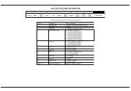
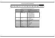
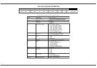
SpecificationsGeneralFrameItemFrame TypeFront SuspensionRear SuspensionFront tireRear tireFront brakeRear brakeFuel capacityFuel reserve capacityCaster angleTrail lengthFront fork oil capacityTravelTravelAir pressureSizeAir pressureSizeAir pressureLeft:Standard...._ ..__ _ .._-- ._.._ ..__ _ ....•..- __ _.__....••._ _----------------/Dimensions Overall length 2,615 mm (103.0 in)Overall width955 mm (37.6 in)EngineOverall heightWheelbaseSeat heightGround clearanceDry weightCurb Weight1,495 mm (58.9 in)1,690 mm (66.5 in)740 mm (29.1 in)115 mm (4.5 in)A: 364 kg (802 Ibs), California rnodel: 365 kg (805 Ibs)SE: 370 kg (816 Ibs), California model: 371 kg (818 Ibs)I: 349 kg (769 Ibs), California model: 350 kg (771 Ibs)A: 399 kg (879 Ibs), California model: 400 kg (882 Ibs)SE: 405 kg (893 Ibs), California model: 406 kg (895 Ibs)I: 385 kg (848 Ibs), California model: 386 kg (851 Ibs)..•.- _ _ .._-- ._.- _ _ ..- _ _ ..- _ .....•._ .._ - ._...•_ .....•_ - _ _ _-_..•_ _ ..-Double cradleTelescopic, 140 mm (5.5 in)Swing arm, 105 mm (4.1 in)0-4.0 kg/cm 2 (0·57 psi)130/70-18 63H2.25 kg/cm 2 (33 psi)160/80-1675HUp to 90 kg (200 Ibs) load: 2.50 kglcm 2 (36 psi)Up to maximurn weight limit: 2.80 kg/cm 2 (41 psi)Double disc brakeDisc brake24.0 lit. (6.3 US gal, 5.3 Imp gal)5.3 lit (1.4 US gal, 1.2 Imp gal)30°111 mm (4.4 in)A & SE: 372 cc (12.6 US oz, 13.1 Imp oz)I: 361 cc (12.2 US OZ, 12.7 Imp oz)377 cc (12.7 US OZ, 13.2 Imp oz)Right:.._ _ _ _ _ - _ _ .....•_ - _ _ _ .._ - _ _ _ _ _ _ ..- _ _ _._.•.._ .._ __.Water cooled, 4-stroke O.H.C.Flat six71 x 64 mm (2.8 x 2.5 in)Engine typeCylinder arrangementBore and strokeDisplacementCompression ratioValve trainOil capacityLubrication systemCooling system capacityCylinder compressionEngine weightAt disassemblyAfter oil/filter changeCamshaft Intake valve OpensClosesCamshaft Exhaust valve OpensClosesValve clearanceIntake/ExhaustIdle speed._-~------1,520 cc (92.7 cu-in)9.8:1Belt-driven overhead camshaft4.3 lit. (4.5 US qt, 3.8 Imp qt)3.7 lit. (3.9 US qt, 3.3 Imp qt)Forced and wet sump4.1 lit. (4.3 US qt, 3.6 Imp qt)15.0 kg/cm 2 (213 psi)A & SE: 126 kg (278Ibs)I: 124 kg (273Ibs)5° ATDC (At 1 mm lift)30° ABDC (At 1 mm lift)40° BBDC (At 1 mm lift)5° BTDC (At 1 mm lift)Hydraulic valve adjuster system800±80 rpm2-2goldwingdocs.com
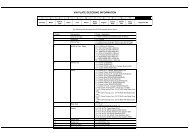
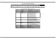
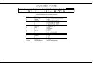
---"~-"'-"'---'-----------''''''-''''--r------------'-'''''---~-----1-------..._-_.._Unit: mm (in) .._--------_.----_...-CarburetionItem.._-_._------------_.._ .._ ...._-Standard..__..._ .....__....•-Carburetor typeCV down-draft - (2)Throttle bore36 mm (1.42 in)Carburetor identification No.A & SE: VO GWE; California model: VO GYO; Canada model: VO G9CI: VO GWF; California model: VO GYE; Canada model: VO G9CPilot screw opening See page 4-39Float level7.5 mm (0.3 in)Main jet pri: #80 2nd: #148Slow jet #65Throttle grip free play5-8 mm (3/16-5/16 in)Fuel pump flow capacity640 cc (21.6 oz)/minuteCarburetor vacuum differenceWithin 40 mm (1.6 in)Hg of each otherr------j·-···-·-·-·-··-·--..-···--·--·--····-· - ....- ...- ..-.-.....__... _Drive Train Clutch typeWet, multi-plateTransmission5-speed, constant meshPrimary reduction ratio 1.592 (78/49)Secondary reduction ratio 0.971 (34/35)Gear ratioFinal reduction ratioGearshift patternFinal drive gear oil capacity1st 2.666(40/15)2nd 1.722(31/18)3rd 1.272 (28/22)4th 0.964 (27/28)00 0.758 (22/29)2.833 (34/12)Left foot operated return system 1-N-2-3-4-00140 cc (4.7 US oz, 4.9 Imp oz) (After draining)170 cc (5.7 US oz, 6.0 Imp oz) (After disassembly)r-----t---------·-----------t----..- ..--....--------------- -1ElectricalBattery Ignition (Full transistor)TOC @ 800 ± 80 rpmStarting motorA.C. generator, S50 W/S,OOO rpmIgnitionIgnition timing "F" markStarting systemAlternatorAlternator driven gear damper springfree lengthBattery capacitySpark plug - StandardSpark plug gapFiring orderFuses FuseboxMain fuse- For cold climate (Below SO°C, 41°F)- For extended high speed riding20.8 mm (0.82 in)12V-20AHOPR7EA-9 (NGK)X22EPR-U9 (Nippondenso)OPR6EA-9 (NGK)X20EPR-U9 (Nippondenso)OPR8EA-9 (NGK)X24EPR-U9 (Nippondenso)0.8.-0.9 mm (0.031-0.035)1-4-5-2-3-6A & SE: 5A x 4, 10A x 4, 15A x 5; I: 5A x 3, 10A x 3, 15A x 530A,55AA & SE: 5A x 2, 65AReverse fuset-----..------1-------------------_.._ ..- .....- ..- ...--..- ....---.- . .._ ..__.._ ..._Lights Headlight 12V 45/45W x 2Position light 12V 2cp (3.4W) x 2Turn signal/position light 12V 32cp (23W)/3cp (8W) x 2Indicator light A & SE: 12V 3.4W x 5; 12V 1.7W x 4; I: 12V 3.4 x 3, 12V 1.7W x 2Turn signal indicator 12V 3W x 2Meter illumination 12V 3.4W x 4LCD unit illumination 12V 3W x 2License light12V 3cp (5W)Accessory light 12V 3W x 2Brake and taillight 12V 32/2cp (27/7W) x 4Rear turn signal 12V 32cp (23W) x 2~,,_._""" ~,,0__rn_e_ri_ng;;....;lig'-h_t..;.(S~E..;.) "'__.__-L1:..:2:.;V....:2:.:S:..::W..:....:.,;x.;;;2:..-- .....J.'_goldwingdocs.com
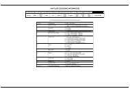
SpecificationsStandards/<strong>Service</strong> limits--c r d~ ym ar HaadItem Standard Unit: mm (in)~--- -------_._..._.. ...._ ..•._ ....._......_ .....- ._..~.._.__...._ ..__._.._ <strong>Service</strong> limit___...__..~".-f----------------Cylinder Cylinder head warpage 0_10 (0.004)Head Valve stem 0.0. IN 5.475-5.490 (0.2156-0.2161) 5.45 (0.215)EX 5.455-5.470 (0.2148-0.2154) 5.44 (0.214)Valve guide 1.0. IN, EX 5.500-5.512 (0.2165-0.2170) 5.55 (0.219)Valve stem-to-guide clearance IN 0.010-0.037 (0.0004-0.0015) 0.08 (0.003)EX 0.030-0.057 (0.0012-0.0022) 0.10(0.004)Valve seat width 1.2 (0.05)Valve spring tree length 44.6 (1.76) 43.3 (1.70)Valve spring preload/length15.6-18.2/37.5 kglmm(34.49-40.12/1.48 Ibs/in)Rocker arm 1.0. 25.000-25.021 (0.9843-0.9851) 25.05 (0.986)Rocker arm shaft 0.0. 11.966-11.984 (0.4711-0.4718) 11.95 (0.470)Rocker arm lobe 1.0. 11.996-12.031 (0.4723-0.4734) 12.07 (0.475)0.0. 20.945-20.980 (0.8246-0.8260) 20.93 (0.824)Hydraulic valve adjuster compression stroke 0-0.30 (0-0.012) 0.30 (0.012)with kerosene-- ._----..._."._....._._..._ .._ ...,._....- ---_......_max..._--- --..__._---------Camshaft Cam lobe height 36.110-36.190 (1.4217-1.42480) 35.9 (1.41)Runout (at inner journals) 0.10(0.004)Journal 0.0. Both inner 26.934-26.955 (1.0604-1.0612) 26.91 (1.059)Both ends 26.949-26.970 (1.0610-1.0618) 26.91 (1.059)Holder, Journal 1.0. 27.000-27.021 (1.0630-1.0638) 27.05 (1.065)Journal oil clearance Both inner 0.045-0.087 (0.0018-0.0034) 0.14 (0.006)Both ends 0.030-0.072 (0.0012-0.0028) 0.14 (0.006)Cylinder Cylinder compression pressure 13.0-17.0 kg/cm 2 (185-242 psi)10 kg/cm 2(142 psi)Cylinder 1.0. 71.010-71.025 (2.7957-2.7963) 71.1 (2.80)Out-ot-round 0.15 (0.006)Taper 0.05 (0.002)Top warpage 0.05 (0.002)~-----------t-----------------------..----------- I-------------........-----..--- .. --------------------....---t--....-_Piston Piston 0.0. (at skirt) 70.960-70.990 (2.7937-2.7949) 70.85 (2.789)Piston pin bore 18.010-18.016 (0.7091-0.'7093) 18.03 (0.710)Piston-to-cylinder clearance 0.015-0.065 (0.0006-0.0026) 0.10 (0.004)Piston ring End gap Top and second 0.15-0.30 (0.006-0.012) 0.5 (0.02)Oil ring side rail 0.20-0'-70 (0.008-0.028) 0.9 (0.04)Ring-to-ring Top 0.025-0.055 (0.0010-0.0022) 0.10(0.004)land clearance Second 0.015-0.045 (0.0006-0.0018) 0.10(0.004)Piston pin 0.0. (at sliding surfaces) 17.994-18.000 (0.7084-0.7087) 18.99 (0.748)Pin-to-piston clearance 0.010-0.022 (0.0004-0.0009) 0.05 (0.002)Pin-to-rod interferencef------ -----0.015-0.039 (0.0006-0.0015). ... .. .. ... .. _Crankshaft Main journal bearing oil clearance 0.020-0.038 (0.0008-0.0015) 0.06 (0.002)Crankpin bearing oil clearance 0.027-0.045 (0.0011-0.0018) 0.06 (0.002)Crankshaft runout (at center journal) 0.03 (0.001)Connecting rod side clearance 0.15-0.30 (0.006-0.012) 0.40 (0.016)Crankpin and main journal Taper 0.003 (0.0001)Out-ot-round 0.005 (0.0002)goldwingdocs.com
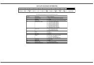
~CIuc t h,-~'"~"""~Item~.... ......_...-Standard_._.....Unit: mm (in) <strong>Service</strong> LimitClutch master Cylinder 1.0. 15.870-15.913 (0.6248-0.6265) 15.93 (0.627)cylinder Piston 0.0. 15.827-15.854 (0.6231-0.6242) 15.82 (0.623)..._-_....-._---Clutch Plate warpage 0.30 (0.012)Disc thickness 3.72-3.88 (0.146-0.153) 3.5 (0.14)Clutch spring free height 5.38 (0.212) 5.1 (0.20)Clutch fluid DOT 4Oil PumpsMain oil pump Tip clearance 0.15 (0.006) max. 0.35 (0.014)Pump body clearance 0.15-0.23 (0.006-0.009) 0.43 (0.017)Pump side clearance._---0.02-0.07 (0.001-0.003) 0.12 (0.005)Scavenging Tip clearance 0.15 (0.006) max. 0.35 (0.014)pumpPump body clearance 0.15-0.23 (0.006-0.009) 0.43 (0.017)Pump side clearance....._.....0.02-0.07 (0.001-0.003)._._.0.12 (0.005)Pressure Relief pressure4.7-5.7 kg/cm 2 , 67-81 psirelief valve Relief valve spring free length_ ......_.._.._..90.8 (3.57) 84.0 (3.31)Oil pressure Cold ( At 35°C/95°F) Idle speed 1.3 kg/cm 2 , (18 psi)(at oil pressure switch) 5,000 rpm 5.0 kg/cm 2 , (71 psi)Hot (At 80°C/176°F) Idle speed 0.8 kg/cm 2 , (11 psi)(at oil pressure switch) 5,000 rpm 5.0 kg/cm 2 , (71 psi)Oil pressure switch continuity pressure0.1-0.2 kglcm 2 , (1-3 psi).~ Transmlsslon --Transmission Gear I.D. C2, C3, M4, M5 34.000-34.016 (1 .3386-1.3392) 34.04 (1.340)Gear bushing 0.0. C2, C3, M4, M5 33.940-33.965 (1.3362-1.3372) 33.92 (1.335)Gear-to-bushing clearance_..__.0.035-0.076 (0.0014-0.0030) 0.10 (0.004)Gearshift Shift fork shaft 0.0. 13.966-13.984 (0.5498-0.5506) 13.90 (0.547)Shift fork 1.0. 14.000-14.021 (0.5512-0.5520) 14.04 (0.553)Claw thickness 5.93-6.00 (0.233-0.236) 5.6 (0.22)CoolingCoolingRadiator cap relief pressureThermostat Begins to open temperatureFully opened temperatureValve lift (heated to 95°C/5 minutesCarburetor coolant thermal valve Starts to closeThermostatic fan motor switchCoolant temperature sensorresistanceFreezing point (Hydrometer test)California modelStarts to close60°C (140° F)85°C (185°F)110°C (230°F)120°C (248°F)Radiator After disassemblycoolant After draining (including reserve tank).capacity Reserve tankBoiling point (with 50-50 mixture)0.75-1.05 kg/cm 2 (11-15 psi)80 c -84°C (176°-182°F)93°-9rC (199°-206°F)8.0 (0.31) min.78°-82°C (172°-180°F)58°-62°C (136°-144°F)98°-102°C (208°-216°F)104 ohms44 ohms20 ohms16 ohms4.1 lit (4.3 US qt, 3.6 Imp qt)3.8 lit (4.0 US qt, 3.3 Imp qt)0.55 lit (0.6 US qt, 0.5 Imp qt)Unpressurized: 107,rC (226°F)Cap on pressurized: 125.6°C (258°F)55% Distilled water + 45% ethylene glycol:-32°C (-26° F)50% Distilled water + 50% ethylene glycol:-3rC (-35°F)45% Distilled water + 55% ethylene glycol:-44.5°C (-48° F)goldwingdocs.com2-5
SpecificationsStandards/<strong>Service</strong> limits (ccmt'd)F ID" ,- ~,,~Item Standard Unit: mm (in) <strong>Service</strong> Limit1----- ------_._---_.. -Final Drive Final gear oil Recommended oil Hypoid gear oil, SAE #80Capacity: After disassembly 170 cc (5.7 US oz, 6.0 Imp oz)After draining140 cc (4.7 US oz, 4.9 Imp oz)Final gear backlash 0.05-0.15 (0.002-0.006) 0.3 (0.01)Difference at 3 points 0.10(0.004)Ring gear-to-stop pin clearance---_.._-----_.._---_....0.30-0.60 (0.012-0.024)Output Shaft Damper spring free length 60.82 (2.394) 57.0 (2.24)Shaft 0.0. 22.008-22.021 (0.8665-0.8670) 21.99 (0.866)Collar 1.0. 22.026-22.041 (0.8672-0.8678) 22.05 (0.868)0.0. 25.959-25.980 (1.0220-1.0228) 25.95 (1.022)Drive gear 1.0. 26.000-26.016 (1.0236-1.0242) 26.03 (1.025)="-~r--- S Uspension -,~~~-==,~Fork Forl< spring free length 390.6 (15.38) 382.8 (15.07)Forl< oil capacity Left A & SE: 372 cc (12.6 US OZ, 13.1 Imp oz)I: 361 cc (12.2 US oz, 12.7 Imp oz)Right377 cc (12.7 US oz, 13.2 Imp oz)Fork oil level (from top of tube) 194 (7.6)_.Fork oilPro <strong>Honda</strong> Suspension Fluid SS-8Fork tube runout 0.2 (0.01)Shocks Right shock absorber air pressure 0-4.0 kg/cm 2 (0-57 psi)Right shock absorber oil capacity140 cc (4.7 US oz, 4.9 Imp oz)Right shock absorber oilPro <strong>Honda</strong> Suspension Fluid SS-7"Front Brakes Front brake master cylinder Cylinder 1.0.Piston 0.0.12.700-12.743 (0.5000-0.5017)12.657-12.684 (0.4983-0.4994)12.755 (0.5022)12.645 (0.4978)Front brake caliperFront brake discLeftRightCylinder 1.0.Piston 0.0Cylinder 1.0.Piston 0.0.ThicknessRunout25.400-25.450 (1.0000-1.0020)25.335-25.368 (0.9974-0.9987)30.230-30.280 (1.1902-1.1921)30.165-30.198 (1.1876-1.1889)5.8-6.2 (0.23-0.24)25.460 (1.0024)25.310 (0.9965)30.290 (1.1925)30.140 (1.1866)5.0 (0.20)0.3 (0.01)Front brake pad thickness 5.5 (0.22)~-----~------'----------------It-----'-'------_...-._...__...- ...-1.0 (0.04)----+-_.__..-_..-Rear Brake Rear brake master cylinder Cylinder 1.0. 15.870-15.913 (0.6248-0.6265) 15.925 (0.6270)Piston 0.0. 15.827-15.854 (0.6231-0.6242) 15.815 (0.6226)Brake rod clevis 100 (3.9)installed lengthRear brake caliperRear brake discCylinder 1.0.Piston 0.0.ThicknessRunout32.030-32.080 (1.2610-1.2630)31.948-31.998 (1.2578-1.2598)7.3-7.7 (0.29-0.30)32.090 (1.2634)31.940 (1.2575)6.0 (0.24)0.3 (0.01)1.0 (0.04)2-6goldwingdocs.com
- Whees lIT" Ires -Item Standard Unit: mm (in)_.-<strong>Service</strong> LimitWheel axle runout 0.2 (0.01)Wheel rim runout Axial 2.0 (0.08)Radial 2.0 (0.08)Tire tread depth Front 1.5 (0.06)Rear 2.0 (0.08)ChargingStarter/ReverseBattery capacityBattery specific gravity(At 20 c C/68° F)Battery charging currentAlternatorRegulator/Rectifier(into alternator)Firing orderIgnition timingIgnition coilresistance(At 20°C/68°F)Full chargedNeeds chargingCapacityStator coil resistanceRotor coil resistanceRotor coil slip ring 0.0.Charging startTypeRegulated Voltage(At20"C/68 C F)VacuumadvancePrimary coilSecondary coil900 rpm1,850 rpmr--'~~~'-I--~~~~~~~~~~~~~~~~~'--IgnitionF markAdvance startAdvance ceaseWith spark plugwireWithout sparkplug wireIgnition pulse generator coil resistance (At 20°C/68°F)Engine coolant temperature sensor/Intake air temperature sensor--~~~~~~~~~._-+----_.._-Starter motor brush lengthReverse System Starter relay regulator/regulated currentResister Between relay and unitterminalsBetween relay terminaland ground12V-20AH1.270-1.290Below 1.2602.0 Amperes max.0.55 kW/5,000 rpm0.1-0.3 ohms (20°C, 68°F)2.9-4.0 ohms (20°C, 68°F)27.0 (1.06)800-1,000 rpmTransistorized non-adjustable reg.lrecti.0-2A, 13.5··15.5 V1.5 A min, 13.5-15.5 V1-4-5-2-3-6-100 TOC at 800 ± 80 rpm650-750 mmHg (25.6-29.5 inHg)380-480 mmHg (15.0-18.9 inHg)2.6-3.2 ohms20.2-26.8 k ohms11.7-14.3 k ohms400-500 ohms2.0-3.0 k ohms200-400 ohms12.5 (0.49)0.7-1.0A0.06-0.09 ohms0.1-0.2 ohms26.0 (1.02).--------+-----------f6.0 (0.24)I--~~~~--t~~-~~~~....-- ....--_.-..- ..._...~~~~~~- -~~~--~~~_+~~~~~~__IElectricalOil pressure switch continuity pressure0.1-0.2 kg/cm 2 (1-3 psi)Fuel gauge level sensor Empty 90-100 ohmsresistance (At 20°C/68°F) Reserve 66-81 ohmsFull4-10 ohmsgoldwingdocs.com
SpecificationsTorque Values="",,,Engine._-~,~,,- "'=.'.,........=,=..~..,."""',"=""=.,"--~'"....__.-Item",= " .............."'--...__..__..-QtyThreadTorquedia (mm) N-m kg-m ft-IbRemarks6 12 15 1.6--- ----_.11Spark plugCarburetor insulator band screw 4 5 5 0.5 3.6Intake manifold vacuum tube joint 4 5 2.8 0.28 2Water hose clamp screw 2 4 2.0 0.2 1.4Coolant temperature sensor 1 PT 1:8 12 1.2 9 NOTE 1Thermostatic fan motor switch 1 16 18 1.8 13Engine coolant temperature sensor 1 12 28 2.8 20Reverse switch 1 10 12 1.2 9Reverse shifter shaft bolt 1 6 14 1.4 10 NOTE 2lubricationOil pressure switch PT 1/8 12 1.2 9 NOTE 1Engine oil drain bolt 14 35 3.5 25Engine oil filter cartridge 20 10 1.0 7Engine oil filter boss 20 17 7.7 12 NOTE 2Cylinder HeadCylinder head bolt (9 mm bolt) 16 9 45 4.5 33 NOTE 3Timing belt driven pulley bolt 2 8 27 2.7 20Camshaft holder bolt 16 8 20 2.0 14Hydraulic valve adjuster stopper plug 12 14 30 3.0 22Cylinder head cover bolt 12 6 12 1.2 9Timing belt tensioner bolt 4 8 26 2.6 19 NOTE 2Cylinder head sealing bolt 6 18 45 4.5 33 NOTE 2ClutchClutch hose/pipe oil bolt 3 10 35 3.5 25Clutch slave cylinder bleed valve 1 8 9 0.9 7Clutch bleed pipe bolt 1 6 12 1.2 9 NOTE 2Clutch center lock nut 1 22 130 13.0 94Clutch outer lock nut 1 40 190 19.0 137 NOTE 2/5AlternatorFront cover attaching screw 3 4 2 0.2 1.4 NOTE 2Couple A mounting nut 1 14 58 5.8 42 NOTE 2Couple B mounting nut 1 14 58 5.8 42Rear Engine CaseStarter one-way clutch socket bolt 6 6 16 1.6 12 NOTE 2Starter clutch mounting bolt 1 12 75 7.5 54Alternator drive gear bolt 6 8 27 2.7 20 NOTE 6Final drive gear lock nut 1 22 190 19.0 137 NOTE 2/4/5Output shaft lock nut 1 30 190 19.0 137 NOTE 5Oil pump driven sprocket bolt 1 6 18 1.8 13 NOTE 2GearshiftShift arm lock bolt 8 25 2.5 18Shift drum center bolt 8 28 2.8 20Shift drum lock arm bolt 6 12 1.2 9 NOTE 2Shift arm return spring pin 8 25 2.5 18Engine Case/CrankshaftlTransmissionEngine case bolt (10 mm) 8 10 35 3.5 25 NOTE 6(8mm) 4 8 26 2.6 19(6mm) 10 6 12 1.2 9Engine case sealing bolt (20 mm) 4 20 45 4.5 33 NOTE 2Mainshaft lock nut(18 mm) 2 18 45 4.5 33 NOTE 21 22 190 19.0 137 NOTE 4/5Crankshaft main bearing cap bolt 8 10 70 7.0 51 NOTE 6Connecting rod cap nut 8 8 32 3.2 23 NOTE 6Timing belt drive pulley bolt 1 12.._-_.75 7.5 54NOTES:1. Apply sealant to the threads. 5. Stake (2 places).2. Apply locking agent to the threads. 6. Apply oil to the threads and flange surfaces.3. Apply molybdenum disulfide oil to the threads 7. Torque wrench scale reading using a special tool.and flange surfaces.8. Apply grease to the threads and flange surfaces.4. left-handed threads...._ ..=~,~~"'''=--~ "~"=..m=",,,,==,,,,,~=,,,,,_.._,,,,2~8goldwingdocs.com
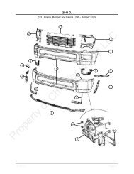
Frame,,~---~ , .~
SpecificationsTorque Values (ccmt'd)FrameItemHydraulic Brake:Caliper bleed valveFront caliper bracket bolt (A & SE)Anti-dive piston bolt (A & SE)(I)Left front caliper bracket bolt (I)Right front caliper bracket bolt (I)Front pad pin plugFront pad pinBrake hose boltRear caliper retainer boltRear caliper boltRear caliper pin boltMetal brake line nutOther~:Brake disc boltMiscellaneous:Side stand pivot boltSide stand lock nutSide stand switch mounting boltCenter stand pivot boltExhaust pipe joint nutTail spoiler mounting bolt (SE)Passenger footrest bracket bolt (SE)Passenger footrest cover bolt (I)Flairing inner cover boltAir cleaner tube joint screwStarter motor cable nutAntenna lock nutQty3221214461114181111124422221ThreadTorquedia (mm) N-m k9-m.~. ..·..u_••"'_.-'...__..._ ......a 6 o.a623 2. 36 12 1. 26 12 1. 2a 31 3. 1a 23 2. 31010102.51835O. 251. 83. 56 11 1. 1a 23 2. 3121028172. 81. 7a 40 4.oo9o8o610 10 1.10 29 2.6 10 1.a 18 1.6 10 1.6 6 o.a 26 2. 66 10 1. o6 10 1. o5 0.3 O. 03- 0.5 O. 058 10 1. oft-Ib4179922171.8132581720122972171374.319770.20.47RemarksTorque specifications listed above are for important fasteners. Others should be tightened to standard torque values listed below.Standard Torque ValuesItem5 mm bolt and nut6 mm bolt and nuta mm bolt and nut10 mm bolt and nut12 mm bolt and nutTorque ValuesN-m (kg-m, ft-Ib)..- ...- ....__..._._....~.._ .._ ..__....-5 (0.5, 4)19 (1.0, 7)22 (2.2,16)35 (3.5, 25)55 (5.5, 40)_ ........ . _.l..-_. ~Item5 mm screw6 mm screw and 6 mmflange bolt with 8mm head6 mm flange bolt and nuta mm flange bolt and nut10 mm flange bolt and nutTorque ValuesN-m (kg-m, ft-Ib).._ ....---"_....._ ..._ .._ ...,_.-._.4 (0.4, 3)9 (0.9, 7)12 (1.2, 9)27 (2.7, 20)40 (4.0, 29).b___• .. .......goldwingdocs.com
Maintenance<strong>Service</strong> Information 3..2Lubrication Points 3..3Troubleshooting 3..7Maintenance Schedule .. 3..12Engine Oil Level 3..13Engine on and FilterChange 3..13Oil Pressure Check 3..14Final Drive Oil 3..15Fuel Line . 3..16Throttle Operation 3..16Carburetor Choke 3..17Air Cleaner 3..18Crankcase Breather 3..19Spark Plugs 3..19CarburetorSynchronization 3..20Carburetor Idle Speed .. 3..21Cylinder Compression .. 3..21Radiator Coolant 3..22Cooling System 3..23Pulse Secondary AirInjection System 3..24Evaporative EmissionControl System 3..24Battery 3..25Brake Fluid 3..26Brake Pad Wear 3..26Brake System 3..27Brake Light Switch 3..28Headlight Aim 3..28Clutch System 3..29Clutch Fluid 3..29Reverse Operation 3..30Side Stand 3..31Suspension 3..31Air Pump Element 3..33Air Drier 3..34Cruise Valve Element 3..35Nuts, Bolts, Fasteners .. 3..35WheelsfTires 3..36Steering Head Bearings .3..37goldwingdocs.com
Maintenance<strong>Service</strong> Information ~~~~""""~~~----------""'"eeeSupport the motorcycle on the center stand on a level surface before starting any work.When the engine must be running to do some work, make sure the area is well ventilated. Never run theengine in a closed area. The exhaust contains poisonous carbon monoxide gas that may cause loss ofconsciousness and lead to death.Any attempt to mount passenger car tires on a motorcycle rim may cause the tire bead to separate fromthe rim with enough explosive force to cause serious injury or death.Always use the center stand when adjusting ail' pressures. Do not use the side stand when adjusting@~,,~air pressur~, as you will get false pressure""readings. ,_~_,__,,~ _@ For engine oil capacity, see page 2-2.@ For engine oil filter, see page 3-13.@ For final drive oil capacity, see page 2-6.@ For coolant capacity, see page 2-5.o For oil pressure switch inspection, see page 19-23.o The lubrication system uses two oil pumps; main and scavenging. The main pump picks up oil from the crankcaseand delivers it under pressure to the bearings and other important parts of the engine. It is equipped with apressure relief valveo The scavenging pump draws oil from the clutch housing in the rear engine cover and sends it to the primary driveand driven gears to lubricate and cool them.@ To remove the main oil pump and scavenging pump, see Section 8@ The following abbreviations are used to identify wire colors in the circuit schematics:BLKBLUBRNGRNGRYLT BLUblackbluebrowngreengraylight blueLT GRNORNPNKREDWHTYELlight greenorangepinkredwhiteyellow@The fuel tank does not have a drain bolt. While installed on the motorcycle, the fuel tank may be drained by usinga vacuum pump to drain fuel from the fuel filler mouth or by jumping a power source to the fuel pump to drain fuelfrom the fuel tube at the carburetor.@This motorcycle is equipped with tubeless tires, valves, and wheel rims. Use only tires marked "TUBELESS" andtubeless valves on rims marked 'TUBELESS TIRE APPLICABLE." Never mount tires designed for use on automobileson a motorcycle rim.Torque ValuesOil pressure switchEngine oil drain boltEngine oil filter cartridgeFinal drive gear case filler cap12 N-m (1.2 kg-m, 9 ft-Ib) .- Apply sealant.38 N-m (3.8 kg-m, 27 ft-Ib)10 N-m (1.0 kg-m, 7 ft-Ib)12 N-m (1.2 kg-m, 9 ft-Ib)goldwingdocs.com
~,m"~lubrication Pointslubrication PointEngineFinal drive gearForkRear shock absorber (riShock absorber air hase joint a-rings"""~~"~''''''--''''- -~,Brake fluid (clutch fluid)Steering head bearingsSteering head bearing dust sealBrake lever pivotClutch lever pivotSpeedometer gearboxSwing arm pivot bearings and dust sealsFront and rear wheel bearingsFront and rear wheel bearing dust seal lipsThrottle grip sliding surfacelubricantRemarks-, ",HONDA 4-stroke Oil orequivalent. API serviceclassification: SF or SGSAE 10WAOHypoid gear oil, SAE 80Pro-<strong>Honda</strong> SuspensionFluid SS-8 or equivalent4.3 lit (5.4 US qt, 3.8 Imp qt)at engine assembly 3.5 lit(3.7 US qt, 3.1 Imp qt,oil changes 3.7 lit (3.0 US qt,3.3 Imp qt) at oil filter and oilchange,--,,-- "140 cc (4.7 oz) after draining170 cc (5.7 oz) at assemblyLeft: 325 cc (11.0 US oz,11.4 Imp oz)<strong>GL1500</strong> I: 320 cc (10.8 US oz,11.2 Imp oz)Right: 320 cc (10.8 US oz,11.2 Imp oz)<strong>GL1500</strong> I: 330 cc (11.2 US oz,11.6 Imp oz)'''='--'='''''"'' .. -~ght) Pro-<strong>Honda</strong> Suspension 140 cc (4.7 US OZ, 4.9 Imp oz)Fluid SS-7 or equivalent- -" -Pro-<strong>Honda</strong> SuspensionFluid SS-7DOT4" ==- , ,--"'''''''' ,.,,,.=--".,,-_..- ,,,,,,,""'-----,,"',"" ~--------Center stand pivotSide stand pivotBrake pedal pivotWindshield adjuster tension plate pivotrenceReverse drum circumfeReverse drum pivot= ..=-"~--~Multipurpose greaseDrive shaft, universal joint<strong>Honda</strong> Moly 60 paste orDrive shaft pinion joint splines and oil seal equivalentFinal driven flange splines ,Brake caliper pivot bolts sliding surface Hi-Temperature siliconeBrake caliper side collarsgrease,-,- ,,~~'""~,--,Speedometer cableLight weight oil,,,,,,nunThrottle and choke cablesReverse cablesm,=,,,,,,'"''''''''''---"""".._-goldwingdocs.com3-3
Maintenance. I formation (cont'd)<strong>Service</strong> n~~~----<strong>Service</strong> Access Guide3..4goldwingdocs.com
<strong>Service</strong> Access GuideRemove the top compartment, trim holder, and/or fairing cover pieces as indicated when service is required for oneof the following. Refer to section 13 for component removal.~umb~;-~ It;;Requiring Remov.;il.~·_,,_1=__ ."-T~-=:.~~~~t__=- "-2 Ignition switch cover...~,="-~.,..".,,,== --~''''''=,-"~=="=».",~ .."."...,,,,,=,,,,,-,,,, ,,,,,=,"',,""""""'.=,............."3".".....='''=,_.~.".~....Top compartment cover=,,---_._~" ..........=4 Top inner cover"="==-=~='=-'~'.~'. ,.,~--=",.=-==,=,="=",........",, '"5 Front grille'''-'''".=",...~,=-~, "',,-" ''''-''''=''''"""",,"''=''''6 Radiator shroud._",,="'=....,...-" = '''='''"-,,,,,---,, "7 Rear side cover8 Front side cover9 Fairing inner cover10 Fairing lower cover11 Under cover12._=,----,=,,~.,,~"'~~13141516-~=,-Disc coverFairing front cover-",,_...._-SaddlebagSeat._....__.. ~." ............,Left Right <strong>Service</strong>._-_...~ ~_... ,,,,,==-- - Fuel lineAir cleaner housi...---,,,,=, ........,,,,.='.,,,-,=.1--..._ ...._._.__...- ..._. - Radiator coolant- - Cooling system ( hoses)- m=._._* Air pump elementBrake system (hoses)* Air drier (desiccant replacement)"-_._"~~. ."-"--,,,,,- - Air drier (inspection window)ng- - Carburetor idle speed---_.~-.-_..__._~'"f----.--... -_.~_.._.....---------- * Cooling system ( radiator cap and hoses. -_....... '"- - Headlight aim,,,,,,,,,,,,-,,, ,,,,,,-=,,=--..- -...._Cooling system ( radiator core)....~.,-f--.* * Clutch system (metalline)BatteryBrake fluid (left front/rear)* * Brake system (hoses),,==,=,>' .I--~...__•..__.._--'''~_._"--~-_.__._--_....;"""".....,"=~""''=''''''- ............'".••===,"""""'",,= f--"-_._~--"'.........."* * Brake system (hoses),==,,,-'-'-'_._._....-=~"==~...~mn* Clutch system (metaI line)* Brake light switch* Reverse operation (cable adjustment)* * Brake system (hoses).- -'-"-'-* Carburetor synchronization* Reverse operation (cable adjustment)* Clutch system ( metal line)* Cruise valve element* * Brake system (hoses)* * Pulse secondary air injection (tubes)~.-.-.->--" .....* * Cooling system ( hoses)* * Pulse secondary air injection system* * (tubes)* * Spark plugs**__._m ****Brake system (hoses)Carburetor synchronizationCylinder compression- - Engine oil filterCooling system ( hoses)* Brake system .tb,--,,-'----....--",-~---"'----lrake pedal height)-----,,,,,goldwingdocs.com3-5
MaintenanceLubrication Diagram~ HVDRAUUCVALVE~ ADJUSTERgoldwingdocs.com
Troubleshooting '=• .-._-~Engln~ will not crank• Battery or charging system faulty (see Section 17)• Starter or starter system faulty (see Section 18)• Engine seized• Switches or accessory faultyEngln~ cranks but will not start• Out of fuel or incorrect fuel• Engine stop switch off• Ignition system faulty (see Section 16)• Fuel filter clogged• Fuel cap vent cloggedEngln~cranks but will not start - cold w~ath~r• Battery weak due to low temperature (see Section 17)• Incorrect choke cable adjustment• Ice in fuel lines, carburetors, fuel tank, or fuel filter• Incorrect engine oil• Water pump iced (incorrect antifreeze ratio)Engine cranks but will not start - ~ngln~ hot• Fuel flow stopped by percolation (vapor lock) in lines, carburetor, orfuel pump• Incorrect starting procedure• EVAP purge control valve faulty (California model only)Runmon (continues to run with Ignition off)• Excessive carbon build-up in engine• Intake pipe leak• Old or incorrect fuellack of power or high speed periormanc~(See "Engine lacks power" and "Poor performance at high speed" formore detailed troubleshooting information.)• Altemator voltage low or battery low• Ignition system faulty (see Section 17)• Improper ignition timing• Intake pipe leaks• Not enough fuel• Valve springs weak or broken• Cylinder head gasket blown• Carburetor malfunction (see Section 4)Misfir~sat idl~• Dirty air cleaner• Spark plugs gapped incorrectly• Spark plug caps faulty• Ignition cables deteriorated• Carburetor problems (choke, clogged jets, high float level, air system,etc.)Midmrange p~riormancepoor• Incorrect spark plug heat range• Faulty spark plugs• Improper ignition timing (see Section 17)• Low engine compression• Low fuel pump pressure• Improperly adjusted throttle linkageAfterlires, ~xplosions In muffler• Ignition system faulty (see Section 171• Retarded ignition timing (see Section 17)• Valve timing faulty• Lean mixture (often due to dirt or water in fuel, or intake air leak)• Leaky or sticking intake valve or weak or broken intake valve spring• Faulty hydraulic valve• Weak or broken exhaust valve spring(s)• Burnt exhaust valve(s)• Carburetor malfunction (Section 4)Pre-Ignition (mixture ignit~s b~for~ spark plugfires)• Hot spot in combustion chamber (carbon particle)• Overheated valve (sticking in guide)• Overheated engineOil level too low• Oil level not replenished frequently enough• External oil leaks• Oil-Up- Worn piston rings- Irnproperly installed piston rings- Worn cylinder• Oil-down- Worn stern seal- Worn valve guideOil I~veltoo high• Pressure relief valve stuck closed• Clogged oil filter, gallery, or metering orifice• Incorrect oil being usedlow oil pressur~• Oil level low• Plugged oil filter or screen• Pressure relief valve stuck open• Oil pump faulty• Internal oil leakage• Incorrect oil being usedOil contamination• Oil or filter not changed often enough• Worn piston ringsOil emulsification• Entry of radiator coolant- Blown cylinder head gasket- Leaky core plug". Leaky coolant passage• Entry of waterNo oil pressure• Oil level too low; no oil• Broken oil pump drive chain• Broken oil pump drive shaft• Internal leaks• Faulty oil pumpgoldwingdocs.com3-7
MaintenanceTroubleshooting (ccmt'd) ~~~Poor Handling1. If steering is heavyCheck tire and suspension pressures-----------.------------"'i!'!'. Steering bearing adjustment nut tootight• Damaged steering head bearings2. If either wheel is wobbling...... • Excessive wheel bearing play• Bent rim• Improperly balanced ormisaligned wheels• Swing arm pivot bearingexcessively worn• Bent frame3. If the motorcycle pulls to one side -=======----~======-__;II!'II!' • Bent frame• Front and rear wheelsnot aligned• Bent front fork• Bent swing armEngine Does Not Sta.rt or Is Hard to Sta.rt1. Check fuel flow to carburetorREACHING CARBURETOR12. Perform spark testGOOD SPARKNOT REACHING CARBURETOR ===-===.11>POSSIBLE CAUSE• Fuel tank empty• Clogged fuel line or fuel filter• Sticking float valve• Faulty fuel pump• Faulty fuel pump relay• Clogged fuel tank cap vent holeWEAK OR NO SPARK '=====~==--"II!' • Ignition system (see Section 16)3. Test cylinder compression LOW COMPRESSION II!' • Low battery charge• Improper valve clearanceCOMPRESSION NORMAL(Faulty hydraulic tappet)• Valve stuck open• Worn cylinder and piston rings• Damaged cylinder head gasket• Seized valve• Improper valve timing• Worn or damaged valve seat• Warped or cracked cylinder head4. Start by following normal procedure ENGINE STARTS BUT STOPS II!' • Improper choke operation• Carburetor incorrectly adjustedENGINE DOES NOT FIRE• Intake pipe leaking• Improper ignition timing(see Section 16)• Fuel contaminated15. Remove and inspect spark plug WET PLUG II!' • Carburetor flooded• Incorrect choke cable free play• Cylinder flooded• Air cleaner dirty• Faulty carburetor (Rich mixture)• Excessive use of the acceleratorpumpgoldwingdocs.com
POSSIBLE CAUSE1. Raise wheels of the ground and spin by hand WHEELS DO NOT SPIN FREELY ~~=~"'""""!iI>lI>o • Brake dragging• Worn or damaged wheel bearingsWHEEL SPINS FREELY• Wheel bearing needs lubricationI. Rear axle nut excessively tight~ • Final gear bearing damaged2. Check the tire pressure PRESSURE LOW ~==~===~==.... Punctured tire• Faulty tire valvePRESSURE NORMALt3. Check clutch slipping CLUTCH SLIPS ==~~=======";iI» • Faulty clutch hydraulic systemCLUTCH ENGAGED PROPERLY~4. Accelerate lightly ENGINE SPEED DOES NOT INCREASE ~-..;.> • Incorrect choke cable free playENGINE SPEED INCREASES5. Check ignition timing INCORRECTCORRECTt6. Check hydraulic valveNOISE NOT HEARD17. Test cylinder compression!NORMAL8. Check carburetor for cloggingNOT CLOGGEDt9. Remove spark plugNOT FOULED OR DISCOLORED~10. Check oil level and conditionCORRECTt11. Remove cylinder had coverand inspect lubrication!VALVE TRAIN LUBRICATED PROPERLY~(confd)• Clutch spring weak• Worn clutch disc/plate• Warped clutch disc/plate• Clogged air cleaner• Restricted fuel flow• Clogged muffler• Clogged fuel tank vent hole• Faulty carburetor• Faulty fuel pump• Faulty fuel pump relay• Faulty hose in emission controlsystem• Faulty EVAP purge control valve(California model only)• Faulty EVAP carburetor air ventcontrol valve (Californiamodel only)~=~========~~+ • Improper ignition timing(see Section 16)NOISE HEAD ======~===~-__.. • Clogged hydraulic valve oil holes• Faulty hydraulic valve• Wrong hydraulic valve shim• Entry of air into hydraulic valve• Worn valve seat or camshaft• Oil level too lowTOO LOW ~============~Il>CLOGGED ~~======~==="'""""!1l>1I>oFOULED OR DISCOLORED ==-~~=__"Il>• Valve stuck open• Worn cylinder and piston rings• Leaking head gasket• Improper valve timing• Faulty hydraulic valve• Carburetornotservicedfrequentlyenough• Plugs not serviced frequentlyenough• Spark plug with incorrect heatrangeINCORRECT =----=-==-~__.. • Oil level too high• Oil level too low• Contaminated oilVALVE TRAIN NOT LUBRICATED PROPERLY";> • Clogged oil passage• Clogged oil control orifice• Clogged oil filter or screengoldwingdocs.com3=9
MaintenanceTroubleshooting (cont'd)Engine lacks Power12. Check for engine overheatingNOT OVERHEATINGOVERHEATING "~"~----------lI!>~POSSIBLE CAUSES• Coolant level too low• Fan motor not working(thermostatic switch faulty)• Thermostat stuck closed• Excessive carbon build-up incombustion chamber• Use of poor quality fuel• Improper ignition timing(see Section 16)• Lean fuel mixture13. Accelerate or run at high speedENGINE DOES NOT KNOCKPoor Performance at Low and Idle Speeds1. Checl< ignition timing and hydraulic INCORRECT---valve noiseCORRECT~2. Check carburetor pilot screw adjustmentCORRECT~3. Check for leaking intakepipe and vacuum tubesNO LEAK~4. Perform spark testPoor Performance at High Speed1. Check ignition timing andhydraulic valve noiseCORRECTt2. Disconnect fuel line at carburetorFUEL FLOWS FREELY13. Remove Carburetors andclogged jetsNO CLOGGED JETS~4. Check valve timingENGINE KNOCKS ----------ll!>ll> • Worn piston and cylinder• Wrong type of fuel• Excessive carbon build-up incombustion chamber• Ignition timing too advanced(see Section 16)• Lean fuel mixture-----~--mm~'_l-lI!>lIl>• Clogged hydraulic valve oilhoses• Faulty hydraulic valve• Improper ignition timingINCORRECT----------~~ • See pilot screw adjustment(Section 4)LEAKING--·~-----------lI!>~WEAK OR INTERMIHENT SPARK----PoPo• Loose carburetor insulator• Damaged or deterioratedvacuum tubes• See ignition system(Section 16)• Faulty carburetor airsystem (see Section 4)INCORRECT -------.----~lIl>po • Clogged hydraulic valve• Faulty hydraulic valve• Improper ignition timing(see Section 16)FUEL FLOW RESTRICTED------~popoCLOGGED---- ----."""""".,,.~• Fuel tank empty• Clogged fuel line or fuel filter• Clogged fuel tank cap vent hole• Sticking float valve• Faulty fuel pump• Faulty fuel pump relay• Carburetor not servicedfrequently enoughINCORRECT-~-----------~po • Camshaft pulley not installedproperlyCORRECT~5. Check valve spring tensionWEAK--------------~1Il> • Faulty springNOT WEAKENED~""-_•.".-------------------------lIl>lI!> • Faulty carburetor air system(Section 4)goldwingdocs.com
Hydraulic Valve Adjuster SystemNoisy Tappet1. Check for low oil level.Ride for five minutes with the enginespeed over 3,000 rpm.Check oil level and condition.CORRECT+2. Check oil pressureCORRECTI3. Remove cylinder head cover and checklubricationCORRECT+4. Remove hydraulic tappet and check it.CORRECT15. Disassembly camshaft holder andcheck partslow Cylinder Compression1. Check oil level andconditionINCORRECTINCORRECTNOT LUBRICATED PROPERLY -=--~... Clogged camshaft holder oilpassage• Clogged oil control orificeINCORRECTINCORRECT ====~=~-""-,~ • Worn or damaged rocker arm orshaft• Worn valve stem• Broken or weak valve spring• Use of improper shim• Improper installation• Worn carnshaftINCORRECTPOSSIBLE CAUSE~~~--~~~-~--'. • Contaminated oil• Use of poor quality oil=--~==--~=---. • Clogged oil filter screen• Clogged oil filter• Oil level too low• Faulty oil pump• Relief valve stuck open• Internal oil leakage• Worn crankshaft bearing• Clogged oil passage• Clogged oil pipe~==~-~==~==~'.• Plunger sticking• Faulty hydraulic tappet• Air in hydraulic tappet• Worn or sticking hydraulic tappet• Improper hydraulic tappetinstallation=-===~=--,,-=,--+ • Contaminated oil• Use of poor quality oilCORRECT+2. Check oil pressure INCORRECT --~~--=-_.=--~+. • Use of poor quality oilNORMAL+3. Remove hydraulic tappetand check itCORRECT+4. Disassemble camshaft holder and checkpartsCORRECT+5. Check valve and valve seatINCORRECTINCORRECT--=~-~~~-~~~-+. . Sticking hydraulic tappet• Faulty hydraulic tappet• Improper hydraulic tappetinstallation=~===~-"==~~ • Worn or damaged rocker armor shaft• Use of improper shim• Improper installationINCORRECT ~m=~~==~= ====-l.~• Worn valve seat or valve faceCORRECT -~-~===~-~==~=~~=~=~~~==~=~~~=-J.~• Engine overrevvinggoldwingdocs.com3..11
MaintenanceMaintenance SchedulePerform the PRE-RIDE INSPECTION in the Owner's <strong>Manual</strong> at each scheduled maintenance period.I: Inspect and Clean, Adjust, Lubricate, or Replace if necessary.C: Clean.R: Replace.-----.------. ---~·~ODOMETERREADING (NC)TE1)FREQUENCY ..,.~ .._ • _ •• .._NOTE x1000 km __1_ ~::.....12.~_~. 25.6 a2.0 38:.~RefertoPageITEM x1000 ml 0.6 4 8 12 16 20 24- -- --"--'-- +--+-----:--j• Fuel Line I I I 3-16~, ,.~---~--._.--.-. +........_+---+--_If--~-+-----• Th rattle Operation_._..._,._-~....I I I 3-16Carburetor Choke I I I 3-17(j) ---......-,.--- ._._.-...._-.~--..... . __m - ••••.........,I---+--+--f--I---:::2: Air Cleaner (Note 2) R R 3-181--+::---..-----. ..---.._--......---+-....- .-::-+-:,,""';-"'""::--1 --..+-.......-1---1--------1~ .g_r~an~k~c_a_s_e~_re~~ther (N_ote...~... C C C C C C 3-19o Spark Plugs R R R 3-19~ EngineOil ....__..__.....__.__ _ -+--R R R R 3-13 ,..-ill Engin~_O_il_F_il.!e_r__.._ R R R R +_3_-_13_--1II: Carburetor Synchronization I I I 3-20z: -----._-...---" ----....---~ ....._ ..--.-+-~---+-,..--, '~'" - ..-1--.------1o Engine Idle Speed I I I I I I 3-21CJ5 'Rad-ia-tor Coola-nt-"-'''---'-- .--_.-(-No-te-sj-···..-·,"-"" - ...- ''1'''' -"'- ....-1-.. -·~~R---·t--3--2-2---(f) _~ . • . ...._.,,_...._ ..,,_..._ ....._ ...,,_... .._~ Cooling System I I I 3-23w .----- ------.....---~.- f---._...... - .....-1---- .~-.--+---._.- -.-~--+Pulse Secondary Air InjectionSystem.,,--_._..._.~---_ .. --_._.._ ..._~---+_.+Evaporative Emission 3-24I---.+C_o~n~t!~Syst.~_~. ~Note ~.~.__.. ...I-_--+----'i--Timing Belt___ .. .._ .....__ .. Every 100,O~~.1~?km) I 7-5Final Drive Oil I I R 3-15I--+-~-"-'.--'''- ....----...- ...- ........- -.-..-+----I--+-~_If---+---+---__+-----lBattery I I I 3-25r--+............Brake Fluid (Note 5) I I R I I R 3-26.----..-,--.--. --..-----..- .~----._- ..- --.......,f---+-- ~(f) Brake Pad Wear I I I I I I 3-26~ Brake System,--..--- ..-,.-.----..- ..---.-- '-j'-'-'--'1 I I 3-27I-- ..- .._.-.....-_ ....- .._ ....-.. ...-........_ .....- ....~-_ ........_ ......- f.-- ..- ..........._ ... - ......- -. ~..... - ...- ....- ....~Brake Light Switch I I I 3-28o - ....------..-.-.....- ......~ ...- .....- ..--~ ......-._...-._- ..._ ..__......_ ....- ...-1-.-... ..- ----IW Headlight Aim I I I 3-28!:; ..--._--..".-~._-.- .....-.. _ ......- .....--...--_..--_..-f--..._ ......- ...- f-....-f--...-f..--I-----j-...... Clutch System I I I 3-29ill C'MChFlui'(j-''''''' ·....·-·-(N~te5)1 F-j R I R 3'~~a::.... ..._ ....__.._ ...__....__..__ .._~_..._z . Reverse Operation A & SE models only I I I 3-30o SideStand----·-·-·-·-.. ·--·-~ -'I'" f-.... I I 3-31CJ5 _ _~...._ ...._._....._._... ...__..._ ......_ ....._ ......(j) • Suspension I I I 3-31:::2: F-:--f-::-~-.- .....-.--.. - ...----..- .....- ...- _... .....- - .....--j.--..........jf--f_-----jw Cruise Valve Element A & SE models only R 3-35, 1---.+--_.._--_..._.- ....--..~-- ..+...-.......,--.......,--f_--~z: Air Pump Element A & SE models only C 3-33o 1---.+-..--....._.....- ..--..- ..----...- ...---1-. ...__.... _ ....-.--..4----_1Z Air Drier A & SE models only I I I 3-34..._. ._.-........_~..._--_..-... ...-_.....- ...-_.......-1--......- ......- ...~ -"-'" "- ------_..--....-* Nuts, Bolts, Fasteners I I I I 3-35..... "-'''-''---''-'_._'- ..._._- -..----......- .....- ....-.~.--.......- ..._ ..-.I-.....- ... f.--......_- f-----".- ...-----Wheelsrrires I I I 3-36.........._~- _ _ ~---_._- -.... .. - -~._- --_ _ - - ..- 1-- --1--... . ----Steering Head Bearings I I I I 3-37.L...... .._ ..... ............._ ....._ ....._'--.... ......_ .....~_'"_.... ....._• *Should be serviced by an authorized <strong>Honda</strong> dealer, unless the owner has proper tools and service data and is mechanically qualified.In the interest of safety, we recommend these items be serviced only by an authorized <strong>Honda</strong> dealer.NOTE1. At higher odometer readings, repeat at the frequency interval established here.2. <strong>Service</strong> more frequently when riding in unusually wet or dust areas.3. <strong>Service</strong> more frequently when riding in rain or at full throttle.4. California type only.5. Replace every 2 years, or at indicated odometer interval, whichever cornes first. Replacement requires mechanical skill.-----------_.-goldwingdocs.com3-24
Engine Oil levelStart the engine and let it idle for a few minutes.Stop the engine and put the motorcycle on its center standon level ground.Remove the dipstick, wipe it clean, and insert the dipstickwithout screwing it in.Make sure the oil level is at the upper level mark of the dipstick.If the oil level is low, remove the oil filter cap and addthe necessary amount of recommended oil: <strong>Honda</strong>4-stroke oil or equivalent API service classification SF orSG, SAE 10W-40.The viscosities shown in the chart may be used when theaverage temperature in your riding area is within the indicatedrange.Reinstall the dipstick and oil filler cap. Check that thereare no oil leaks.Check the oil pressure warning light after the enginestarts. The light should go off after one or two seconds.Engine Oil & Filter ChangeSINGLEGRADEMULTIGRADEOIL VISCOSITIES..J.~LLSi(._-10 0 10 20 30 40C20 40 60 80 100°NOTEoChange engine oil with the engine warm and motorcycleon its center stand to assure complete andrapid draining.Stop the engine. Remove the oil filler cap, oil drain bolt,and sealing washer.Remove the under cover (see page 13-11).Remove the oil filter with a filter wrench and let the remainingoil drain out. Discard the oil filter.Tool:Oil filter wrench07HAA-PJ70100Check that the sealing washer on the drain bolt is in goodcondition. Install the bolt.Torque:Replace the oil filter with a new one. Check that the oil filtera-ring is in good condition. Coat it with oil before installation.Install and tighten the oil filter.Torque:38 N-m (3.8 kg-m, 27 it-Il:»10 N·m (1.0 kg-m, 7 H-Il:»~-- I ~l~C/-s;r'_~~~~~~~~, ,\\SEALING WASHEROIL FILTER WRENCHgoldwingdocs.comDRAIN BOLT3=13
MaintenanceEngine Oil and Filter Change (cont'd) ---=-=-~Fill the engine case with the specified quantity of therecommended oil (see page 2-2). Reinstall the oil fillercap and dipstick.Start the engine and let it idle for a few minutes, then stopthe engineMake sure that the oil level is at the upper level mark onthe dipstick.Make sure that there are no oil leaks.Recommended oil:<strong>Honda</strong> Ii-Stroke Oil or EquivalentAPI <strong>Service</strong> Classification - SF or SGSAl: "lOW-liCO-RINGOil Pressure Check-----Remove the under cover (see page 13-11).Disconnect the oil pressure switch wire. Remove the oilpressure switch and attach an oil pressure gauge to thepressure switch hole.Tools:Oil pressure gaugeCommercially availableOil pressure gauge attachmentCommercially availableStart the engine and check the oil pressure.goldwingdocs.com
Stop the engine,Apply sealant to the pressure switch as shown and installit.Torque:12 N~m (1.2 kg-m, 9 ft-Ib)CAUTION" To prevent damage to the engine cover threads,do not overtighten the switch.Connect the switch wire and install the rubber cover.Check that the oil pressure warning light goes out a fewseconds after turning the ignition switch ON.00 NOT COAT THiS AREAJ mm 11:).1 inlCheckPlace the motorcycle on its center stand on level ground.Remove the oil filler cap.Check that the oil level reaches the lower edge of the oilfiller cap hole.Check for leaks, if ttle level is low. Pour fresh oil throughthe oil filler hole until it reaches the lower edge.OIL FILLER CAPChangeRemove the oil filler cap and drain bolt to drain all oil fromthe final gear case. Install the drain bolt securely.Fill the gear case with the recommended oil to the correctlevel (the lower edge of the oil filler cap hole).Oil Capacity: 140 cc (4.7 0::1::) after drainingRecommended Oil: SAE #80Install and tighten the filler capTorque:12 N-m (1.2 kg~m, 9 ft-Ib)FILLERCAPgoldwingdocs.com
MaintenanceFuel line -~=------=---=---=---=---=---Remove the seat and top compartment (see page 13-9).Check the fuel lines. Replace any that show deterioration,damage or leakage.Throttle Operation==------------==..........------~.Check for smooth throttle grip full opening and automaticfull closing in all steering positions.Make sure there is no deterioration, damage, or kinking inthe throttle cables. Replace any damaged parts.If throttle operation is not smooth, check the inner cablecondition. Replace any frayed or kinked cables.Make sure throttle grip free play is 5-8 mm (3/16-5/16 in)at the throttle grip flange.FREEPlAV5-8 mm('%.-0/.. inlTHROTTLE GRIPMake minor adjustments with the throttle grip adjuster asshown.ADJUSTERTo adjust, loosen the lock nut, turn the adjuster asrequired, and tighten the lock nut.LOCI< NUT3=16goldwingdocs.com
Make major throttle grip free play adjustments with thecable adjuster as shown.To adjust, loosen the lock nut, turn the adjuster asrequired, and tighten the lock nut.Recheck throttle operation and install all removed parts.ADJUSTERCarburetor Starting Enrichment Valve """"""'~"""""""'~------The <strong>GL1500</strong> choke system uses a fuel enriching circuitcontrolled by a starting enrichment valve.The starting enrichment valve opens the enriching circuitvia a cable when the choke lever on the handlebar ispulled down.Check for smooth choke lever operation. If operation isnot smooth, check the inner cable condition.Replace the cable if it is frayed or kinked.CHOKE LEVERRemove the air cleaner housing (see page 4-18).When operating the choke lever, check for smooth valveoperation between the fully closed and fully open positions.goldwingdocs.com3-17
MaintenanceCarburetor Choke (cont'd) ----~--------------=To adjust, loosen the lock nut and turn the adjuster asrequired. Tighten the lock nut.Reinstall the removed parts in the reverse order of disassembly.LOCK tuT \ADJUSTERRemove the following:" top compartment (see page 13-9)" air duct" air cleaner housing cover" air cleaner element" California only: evaporative emission storage elementfrom the air cleaner elementNOTE" Do not replace the evaporative emission storageelement.Discard the air cleaner element in accordance with themaintenance schedule.Also, replace the element any time it is excessively dirtyor damaged.Reinstall the evaporative emission storage element in thenew air cleaner element.Install the remaining parts in the reverse order ofremoval.@California ModelEVAPORATIVE EMISSIONSTORAGE ELEMENT[~L_ ;S" Install the air vent pipe with screens as shown.SCREWS3=18goldwingdocs.com
Crankcase Breather ~"""'"MaintemmceRemove the plugs from the crankcase breather tubes toempty any deposits.Install the crankcase breather tube plugs.NOTEe@Make sure that the drain tube is installed to the storagetank.<strong>Service</strong> more frequently when riding in rain, or at fullthrottle, or if the deposit level can be seen in the transparentsection of the drain tube.Removal (not necessary for maintenance)Remove the carburetor (see page 4-19).Remove the crankcase breather storage tank mountingbolt and crankcase breather storage tank.Empty any deposits from the storage tank and reinstall it.BREATHERTUBE PLUGSCMf\lKCASE BREATHERruBe ("A" MARKED TUBE)~o ".~~~RA"KCAS., BREATHER TUBESpark Plugs ----~Remove the fairing lower covers (see page 13-12).Disconnect the spark plug caps and clean any dirt fromaround the spark plug bases,Remove and discard the spark plugs.Measure the new spark plug gap with a wire-type feelergaugeSpark Plug Gap: 0.8-0.9 mm (0.031-0.035 in)If necessary, adjust the gap by carefully bending the sideelectrode. With the plug washer attached, thread eachspark plug in by hand to prevent cross-threading. Tightenthe spark plugs another 1/2 turn with a spark plug wrenchto compress the plug washer.Torque:16 N-m (1.6 kg-m, 12 ft-Ib)Connect the spark plug caps.CENTERELECTRODERecommended SparkPlugs:NGK==w._~.----SIDEELECTRODENO---Standard OPR7EA-9 X22EPR-U9,'"Cold climate (below5° C, 41 0 F):OPR6EA-P X20EPR-U9""""--,,,,,,,,,,,,, """"Extended high speedridingOPR8EA-9 X24EPR·U9b-._~~.______.--goldwingdocs.com
MaintenanceCarburetor Synchronization w-=~ ~~" Synchronize the carburetors with the engine at normaloperating temperature, the transmission in neutral,and the motorcycle supported on its center stand.Remove the following:" fairing lower covers (see page 13-12)." right fairing inner cover (see page 13-12)." NO.6 (GRN) vacuum tube from the left intake manifoldvacuum tube joint." plug and washer from the right intake manifold.Install the vacuum gauge attachment into the right intakemanifold.Install the vacuum gauge probes to the intake manifoldjoints.Tool:Carburetor vacuum gauge set07LMJ-001 01 OA or M937B-021-XXXXXVacuum probe 2"07LMJ-001000A or M983X-350-XXXXXLEFT7C\Ii-T r --NO (> . i i \J \J' i[;• 1 : ' ,~I\:IIGRNI ,~~,: .....~.... ~.•..... :. '.'>.~' ';;.,•...••••.•. '.... '... "=-.. ."ft ..-. '-
Open the top compartment cover.Carburetor Idle Speed ~~~~~~~~~~~~~~~~--_.....,,-----'~~-------_.....~..._-NOTE@ Inspect and adjust idle speed after all other engineadjustments are within specification." The engine must be warm for accurate adjustment.Ten minutes of stop-and-go riding is sufficient."'''~--''''' .Warm the engine, shift to Neutral and place the motorcycleon its center stand. Turn the throttle stop screw asrequired to obtain the specified idle speed.Idle Speed: 800 ± 80 rpmCylinder Compression ~~~~--~~-NOTE@The engine must be warm for accurate readings.Stop the engine, then disconnect the spark plug caps andremove the spark plugs.Turn the engine stop switch OFF.Insert the compression gauge. Open the throttle all theway and crank the engine with the starter motor.NOT:..;:E=----__@Crank the engine until the gauge reading stops rising.The maximum reading is usually reached within 4-7seconds.Compression pressure: 13.0-17.0 kg/cm2 (185-242 psi)If compression is low, check for the following:-Improper valve clearance- Leaky valves- Leaking cylinder head gasket- Worn pistonlring/cylinderIf compression is high, it indicates that carbon depositshave accumulated on the combustion chamber and/orthe piston crown.goldwingdocs.com
MaintenanceRadiator Coolant ~~~=.. The engine must be run at normal operating temperature.RESERVE TANK CAP/LEVEL GAUGEl'\Stop the engineSupport the motorcycle on its center stand.Remove the ignition switch cover (see page 13-9).Remove the reserve tank cap/level gaugeRESERVE TANKThe level should be between the Upper and Lower levels.If necessary fill to the Upper level line with a 50/50 mixtureof distilled water and antifreeze... Avoid scalding; never remove the radiator capwhen the engine is hot. The coolant is underpressure.If the reserve tank is empty, remove the top inner coverand radiator cap (see page 5-7).Run the engine for 2-3 minutes to allow air to escape.Fill the radiator with coolant and install the cap. Fill thereserve tank to the Upper level line of the gauge andinstall the cap.~ \3-22goldwingdocs.com
CoolingSystem---"'-----------------Remove the radiator shroud (see page 13-11).Check the air passages for clogging or damage.Straighten bent fins or collapsed core tubes.Remove insects, mud, or any obstructions with compressedair or a low pressure water spray.Replace the radiator if the air flow is restricted over morethan 20% of the radiating surface.Remove the following:" fairing front cover (see page 13-11)." under cover (see page 13-11)." fairing lower cover (see page 13-12)." right top inner cover (see page 13-9).UPPER RADIATOR HOSEt -)). .-/Check the cooling system hoses for cracks, deterioration,or other damage using a suitable inspection mirror.Replace if necessary.~lOWER RADIATORHOSEWATER HOSES (t. ,;.!~ ~----1"2!#''''''~_I //goldwingdocs.com
MaintenancePulse Secondary Air Injection (PAIR) System -------~Remove the following:@ fairing lower covers (see page 13-12)@ fairing inner covers (see page 13-12)Move the heat guard forward.Using an inspection mirror, check the air supply tubesbetween the pulse Secondary air injection (PAIR) checkvalves and exhaust ports for deterioration, damage, orloose connections. Make sure the tubes are not kinked orpinched.NOTE.. If the tubes show any signs of heat damage, removethe PAIR check valves and inspect for damage (seepage 4-57).~._-_......_'---_.,,--~...__....." ..._--_......".......Check the vacuum tube between PAIR control valve andintake manifold through PAIR solenoid valve for deterioration,damage or loose connections.Make sure the tube is not kinked or pinched.For PAIR solenoid valve inspection, see page 4-58.Evaporative Emission Control System ~~~~~~~~~~~(California model only)Check the hoses between the fuel fill cap, evaporativeemission (EVAP) canister, EVAP purge control valve,EVAP carburetor air vent (CAV) control valve, and carburetorfor deterioration, damage, or loose connections.Also check the tubes for clogging due to bending or twisting.Check the EVAP canister for cracks or damage.Refer to the hoses and tubes routing/connection diagram(see pages 4-7 and 4-8).EVAPCANISTERTO EVAP CAVCONTROL VALVEAND EVAP PURGECONTROL VALVE3..24goldwingdocs.com
Battery =~~--~--~-Remove the right rear side cover (see page 13-8).-'----------Inspect the battery fluid level in each cell.@ The battery gives off explosive gases; keepsparks, flames and cigarettes away. Provideadequate ventilation when charging... The battery contains sulfuric acid (electrolyte).Contact with skin or eyes may cause severebums. Wear protective clothing and a faceshield.If electrolyte gets on your skin, flush withwater.If electrolyte gets in your eyes, flush withwater for at least 15 minutes and call a physician.@ Electrolyte is poisonous.- If swallowed, drink large quantities of wateror milk and follow with milk of magnesia orvegetable oil and call a physician.,t.CAUTIONPIPING AS SHOWN BElOW.BATTERY ~ElBOW';~When the fluid level nears the lower level, refill with distilledwater to the upper level.NOTE" Add only distilled water. Tap water will shorten theservice life of the battery.G Apply a thin coat of grease to the battery terminalswhen installing the batteryBATTERy ~,~~--~------BREATHER TUBE IriiiSEiiTTitE BATTERY _BREATHER)I TUBE SECURElY.MT - 00Replace the battery if sulfation forms or sediments accumulateon the bottom (see page 17-7).Make sure the battery breather tube is routed as shownby the illustration on the battery caution label.IIN'SERT-m BATTERY BREATHER \\ TUBE SECURELY. ;MT2-740goldwingdocs.com
MaintenanceBrake Fluid ,,--~~~~=Support the motorcycle on its center stand. Check the brakelever system (front/right brake) reservoir level with handlebarturned so that the reservoir is level.Remove the rear right side cover (see page 13-8). Checkthe brake pedal system (front/left, rear brake) reservoir level.If the level nears the lower level mark, remove the capor cover, set plate and diaphragm.Fill the reservoir with DOT 4 brake fluid to the upper levelmark.CAUTIONo Do not remove the reservoir cover until the handlebarhas been turned so that the reservoir is level.• Do not mix different types of fluid, as they are not compatiblewith each other.• Do not allow foreign material to enter the system whenfilling the reservoir.~y~~~ spili~~L!he !!!Jid on painted, ~astic or rub~~",,~rts.If the level is low, check the entire system for leaks.Refer to Section 14 for brake bleeding procedures.1/ (@II, =IIIBrake Pad Wear-------Front Brake Pad Wear InspectionInspect the pads visually from the rear of the caliper.Replace the brake pads if the pad wear groove reaches theedge of the brake disc.CAUTION• Always replace the brake pads as a set to assure even~~~~~.~:.._._.w_~,,_ .._.._."''''.....'''.....'''.__.~..''''~._..'''''~.__Refer to page 14-7 for brake pad replacement.FRONTWEAR LIMITRear Brake Pad InspectionInspect the pads visually from the back of the caliper.Replace the brake pads if the pad wear groove reaches theedge of the brake disc.CAUTION• Always replace the brake pads as a set to assure evendiscpre~~re:-.."..__.__,,,..._ .._.__.__REAR3-26goldwingdocs.com
~=="~~'~="'='"General InspectionRemove the following:" disc covers (see page 13-18)." fairing lower covers (see page 13-12).@ front side covers (see page 13-8)." rear side covers (see page 13-8).@ fairing inner covers (see page 13-12).Inspect the brake hoses, metal lines and fittings for deterioration,cracks and signs of leakage. lighten any loosefittings.Replace hoses, metal lines and fittings as required.Brake Pedal Height: Om10 mm (OmO"4 in)Adjust brake pedal height so the pedal is 0-10 mm (0-0.4in) above the upper surface of the foot peg._mm CAUTION• _Incorrect brake pedal height can cause brake@___dr~_._._ ...__... ~_,, _:::7BRAKE HOSES/METAL LINES======------=:::::::,~_\'_~-m-{-(O-.O-:4-i-nl--~-..--/A-====-l FOOT PEG..·.. =====--'To adjust height, remove the right chamber protector (seepage 7-28).Loosen the lock nut and turn the master cylinder pushrod. Tighten the lock nut.@Adjust the following after adjusting pedal height- brake light switch (see next page).- cruise cancel switch (rear brake) (see page 4-72).,.~,,,,,_._.-"ADJUSTING NUTgoldwingdocs.com3-27
MaintenanceBrake Light Switch ~~"""""""'~--------------Remove the right front side cover (see page 13-8).NOTE.. The front brake light switch does not require adjustment.Adjust the brake light switch so the brake light comes onwhen the brake pedal is depressed and brake engagementbegins.Adjust by holding the switch body and turning the adjustingnut. Do not turn the switch body.ADJUSTING NUTHeadlight Aim--------------------NOTE.. Adjust the headlight beam as specified by local laws~~~~.~ulations..",,,__.. An improperly adjusted headlight may blindoncoming drivers, or it may fail to light the roadfor a safe distance.Adjust the headlight beam vertically or horizontally withthe adjusting knob or screws as shown in the chart.NOTE.. When making a minor vertical adjustment, removethe trim holder; when making any horizontal adjustment,remove the front grille.~----------_."''''-'---''VERTICAL HORIZONTALAdjustmentMajor Minor Major Minor_._----_.Knob or screw 1 2 3 4TurnclockwiseTurnL...__......,,_.....__...counterclockwiseDown Up Left LeftUp Down Right Right3-28goldwingdocs.com
Remove the following (refer to Section 13):@ecleft rear side coverleft front side coverleft fairing inner coverInspect the clutch hose, metal line, and fittings for deterioration,cracks, and signs of leakage.Tighten any loose fittings.Replace hoses, metal lines, and fittings as required.Check the system for leaks.Clutch FluidPlace the motorcycle on its center stand.Check the clutch fluid level with the handlebar turned sothat the reservoir is level.Check the clutch fluid level.If the level nears the lower eve mark, remove the cover,set plate, and diaphragm.Fill the reservoir with DOT 4 brake fluid to the upper levelmark." The clutch reservoir upper level mark is inside thereservoir.e Do not allow foreign material to enter the systemwhen filling the reservoir.@ Avoid spilling fluid on painted, plastic or rubber parts.@ Do not remove the reservoir cover until the handlebarhas been turned so that the reservoir is level.@ Do not mix different types of fluid, as they are notcompatible with each other.LOWER LEVELRefer to Section 9 for system bleeding procedures.goldwingdocs.com3=29
MaintenanceReverse Operation (A & SE only)----""""Place the motorcycle on its center stand.Check that the ignition switch is OFF. Remove the rightfront side cover (see page 13-8). Check for smoothoperation of the reverse cables. Lubricate the reversecables, if necessary.Reverse Engagement InspectionCheck both sides of reverse engagement lever alignmentand free play in accordance with the maintenance scheduleShift the reverse lever into the reverse position. Makesure that the reverse gear is engaged by attempting toturn the rear wheel by hand. It will not turn when thereverse gear is engaged.Make sure index mark A aligns with the reference mark.Measure the index mark B free play.Standard:2~3 mm (1/16-118 in)INDEXMARK BINDEX MARK AREFERENCEMARKIf adjustment is necessary, first adjust the index mark Aposition, then adjust the index mark B free play, as follows:Loosen lock nut A and turn adjusting nut A so that indexmark A aligns with the reference mark. Then tighten locknut A.Next, loosen lock nut B and turn adjusting nut B so theindex mark B free play is 2-3 mm (1/16-1/8 in). Thentighten lock nut B.After adjusting the reverse cables, move the reverselever and shift into reverse. Repeat shifting into reverseseveral times.Recheck the lever alignment and free play.INDEX IIIIARK AALIGNINDEX MARK B3=30goldwingdocs.com
Side Stand,=------=Check the side stand ignition cut-off system:@@Place the motorcycle on its center stand and raise theside stand.Start the engine with the transmission in neutral, thenshift the transmission into gear with the clutch leversqueezed." Lower the side stand.@The engine should stop as the side stand is lowered.If there is a problem with the system, check the side standswitch (see Section 16).Check the side stand switch mounting bolts for looseness.Check the side stand switch push pin for damage.Suspensionm-----~Do not ride a vehicle with faulty suspension.Loose, worn, or damaged suspension partsimpair vehicle stability and control.FrontCheck the action of the front forks by compressing themseveral times.Check the entire fork assembly for leaks or damage.Replace damaged components which cannot berepaired.Tighten all nuts and bolts.RearPlace the motorcycle on its center stand. Vigorously pushand pull the rear wheel from side to side. If there is anyfree play or looseness, inspect the swing arm bearings fordamage (see page 12-26).Check the swing arm for damage.Check the shock absorbers for leaks or damage. A & SE:Inspect the air hoses for deterioration and cracks.Replace parts as required.Tighten all nuts and bolts.goldwingdocs.com
__=m..=""'=""='''__~''MaintenanceSuspension (cont'd) -------------~GLi 500 A & SE: Inspect the air pressure of the rightshock absorber with the instrument panel gauge.Turn the ignition switch to ON, P or ACC.The air pressure will appear in the display whenever theP. CHECK button is pushed.NOTE",,,,,,,-,,,,,,-,,,=.==,,,,,,,,,,,,,,,,,,,,,,=,,,,,_.=.,,@o""-,,............,,='............Push the INCREASE or DECREASE button to adjustthe air pressure while pushing the P. CHECK button.• m _Never check or decrease air pressure while riding.Keep both hands on the handlebars whileriding._.--~_...•_ ...-_.__...__..._---------CAUTION@ Always use the center stand when adjusting airpressures. Do not use the side stand whenadjusting the air pressure, as you will get false_press~~~in~_s_. .__.... _The usable air pressure range under normal conditionsis: 0-57 psi (0-4.0 kg/cm 2).Rear AirPressure~ - _ _--ta psi(0 kg/cm 2 )57 psi(4.0 kglcm 2 )Rider/-, -,=•.:.",,---L-AIR PRESSUREConditionsRidingConditionsLoad--+_._.__.._.~.One/No LoadUp tomaximumweight limitOrdinary orcity roadridingIRough roadriding._--'---------'GLi500 I: Place the motorcycle on its center stand onfirm level ground.Open the right saddlebag. Remove the air valve cap.Check the air pressure using a pressure gauge.NOTE@@Some pressure will be lost when removing the gaugefrom the valve. Determine the amount of loss andcompensate accordingly.Do not exceed the recommended air pressure or theride will be harsh and uncomfortable... A small amount of the suspension oil may be releasedwhen the air valve is opened to reduce pressure. Toprevent getting any oil on the saddlebag, remove thevalve from the holder and point it away from the sadd-.._.Ieb?g..~ef?-~ red~.~ng 2Eessure..._,_.._.._ ..._m_AIR VALVE CAP.......- .....__....- ......---_.__.-_ ..__._---,Rear AirPressureo psi(0 kglcm 2 )57 psi Up to(4.0 kg/cm 2 ) maximum___C--r0_nd_i!ion~__._._Rider/Riding-_.._ Load .......:::..........-4-..........:._:....;"..:..:........--\ConditionsOne/ Ordinary orNo Load city roadriding..._.__._._,~_w_eight.l~~._it..........._goldwingdocs.comIRough roadriding
Air Pump Element (A & SE only) ~=------------Remove the left saddlebag (see page 13-17).Remove the air pump mounting bolts and free the pumpfrom the frame.Slide the rubber cover from the air pump motor.Remove the air pump element from the inside of the rubbercover.Wash the element in clean, non-flammable cleaning solventand allow it to dry thoroughly.IB_ Nevel' use gasoline 01' low flash point solventsfor cleaning the element. A fire or explosioncould result_.~.DRV.ISoak the element in Pro <strong>Honda</strong> Foam Filter Oil or equivalentand squeeze out the excess.Reinstall the element in the rubber cover and install thecover onto the motor.WASH INSOLVENTSQUEEZE OUTSOLVENTAND ALLOWTO DRYTHOROUGHLYPRO HONDAFOAM FilTEROllORCLEAN SAESOGEAR OILSQUEEZE OUTEXCESS Oilgoldwingdocs.com3-33
MaintenanceAir Drier (A & SE only) ~--InspectionRemove the seat (see page 13-8).Inspect the desiccant color in the inspection window. Thedesiccant should be blue.If the desiccant is colorless, it must be replaced (seebelow).GLASS WINDOWDesiccant ReplacementNOTE~ Before disassembly, be sure to release air pressure.~".~E~~~.g the air pressure control sWi!~~.:._""....._"_Remove the air pump from the frame and disconnect theair hoses from the drier (see page 12-31).Remove the set ring from the air drier cover.Discard the desiccant. Clean the inside of the drier bodywith clean and dry cloth. Pack new desiccant. Install inthe reverse order of removal.felT PACKINGgoldwingdocs.com
Cruise Valve Element (A & SE only)-----------Remove the left fairing inner cover (see page 13-12).Remove the filter housing from the cruise valve elementassembly.Remove the element from the element housing.Replace the element in accordance with the maintenanceschedule.Nuts, Bolts, Fasteners ~-,================-Check that all chassis nuts and bolts are tightened to correcttorque values (see page 2-8).Check that all cotter pins, safety clips, hose clamps andcable stays are in place.goldwingdocs.com
MaintenanceWheelslTiresNOTE.. Tire pressure should be checked when tires areCOLD.Check the tires for cuts, imbedded nails, or other sharpobjects. Repair or replace, as required. Always replacethe tire if the sidewall is punctured or damaged.RECOMMENDED TIRES AND PRESSURES:""._-Front RearTire Size,,-130170-1863H 160/80-1675HUp to maximumweight IimitCold tireUp to 90 kg (200pressures2.25 (33) 2.50 (36)Ibs) loadkg/cm 2 (psi)Maximum weight185 kg (408 Ibs)limit---Tire BrandTubeless OnlyK177._.._._~unl~_p _".._.._ ..- ~~[2.25 (33) 2.80(41)...-"._.-Check the front and rear wheels for rim runout (see Section15).Replace the tires before tread depth at the center of thetire reaches the following limit:Minimum Tread Depth:Front: 1.5 mm (0.06 in)Rear: 2.0 mm (0.08 in)~!.. The use of tires other than those listed on thetire information label may adversely affect handling... Do not install tube-type tires em tubeless rims.The beads may not seat and the tires could slipon the rims, causing tire deflation... Any attempt to mount passenger car tires on amotorcycle rim may cause the tire bead to separatefrom the rim with enough explosive force tocause serious injury or death.CAUTION.. Do not try to remove tubeless tires without specialtools and rim protectors. You may damagethe rim sealing surface or disfigure the rim.goldwingdocs.com
Steering Head Bearings ---~-------------"""'"Raise the front wheel off the ground using a jack underthe engineCheck that the front wheel turns freely and smoothly fromfull left to full right." Check that the control cables are routed correctly anddo not interfere with steering..~---::~--,Push and pull on the fork sliders and check that there isno free play or looseness.If the steering head bearings do not pass these tests,inspect them for damage and proper adjustment (seeSection 12).goldwingdocs.com3=37
Fuel System<strong>Service</strong> Information .Troubleshooting .4..24..9FuellevelSensorlGaugeAir System CircuitFuel Tank .4..15Diagram .Auto Fuel Valve .4..16Engine Control Module ..Fuel Filter .4..17Intake Air Shot AirAir Cleaner Housing .4..18(IASA) System .4..47Carburetor Removal .Carburetor Separation .4..194..21Carburetor Air JetControl System .Carburetor Disassembly .4..23Intake Air TemperatureCarburetor Assembly ....4..26(lAT) System .Carburetor Tubes/Hoses .4..34Secondary AirCarburetor Installation .4..36Injection System .Intake Manifold .4..37Evaporative EmissionPilot Screw Adjustment ..4..39(EVAP) Control SystemFuel Pump .4..40(California model only)Fuel Reserve Sensors/Cruise Control .Indicator .4..43goldwingdocs.com
Fuel System<strong>Service</strong> Information" Gasoline is extremely flammable and is explosive um.:ler certain conditicms. Work in a well ventilatedarea. Do not smoke or allow flames or sparks in the work area or where gasoline is stored." Do not bend or twist control cables. Damaged control cables will not operate smoothly and may stickor bind, resulting in loss of vehicle control.CAUTION" Connect each numbered tube to the correspondingly numbered part of the solenoid valve, or the airsystem will not work properly.NOTE" If vehicle is to be stored for more than one month, drain the float chambers. Fuel left in the float chambers maycause clogged jets, resulting in starting and driveability complaints. To drain the chambers, remove the radiatorshroud (page 13-11) to gain access to the drain plugs, and then insert the screwdriver and loosen the drain plugs." Refer to Section 3 for throttle/choke cable adjustment." The vacuum chambers, accelerator pump and starting enrichment valve can be removed without removing thecarburetor assembly." The float chambers must be serviced with the carburetors disassembled." When inspecting the fuel pump, reserve sensor, level sensor and air system, check the system components andlines step-by-step according to the Troubleshooting chart." To replace the fuel gauge, see Section 19." The follOWing air systems have the following components (not including air tubes and hoses):- Intake Air Shot Air (IASA) System - Carburetor Air Jet Solenoid Valves, Intake Air Tem-- Carburetor Air Jet Control System perature Sensor, Engine Coolant Temperature Sen-- Intake Air Temperature (lAT) System sor, Engine Control Module, Ignition Pulse- IASA Valve, IASA Check Valve Generator, Sub Air Cleaner- IAT Vacuum Actuator, IAT Control Valve, IAT CheckValve." All hoses used in the evaporation emission control system (California Model only) and pulse secondary air injectionsystem are numbered for identification. When connecting one of these hoses, compare the hose number withthe vacuum carburetor tubes/hoses, page 4-34." Always replace used a-rings and cotter pins with new ones." For carburetor synchronization, see page 3-20." The Intake Air Shot Air (IASA) System supplies air to the intake manifolds during deceleration to prevent suddeninduction of strong manifold vacuum." Tube code example:f~~NO.5goldwingdocs.com
tCALIFORNIA MODELONLYTorqueCarburetor insulator band screw5 N-m (0.5 kg-m, 3.6 ft~lb)goldwingdocs.com4-3
Fuel System<strong>Service</strong> Information (cont'd) -~-System locationFUEL RESERVEINDICATORCARBURETOR AIR JET~__._, SOLENOID VALVESFUELGAUGEFUEL LEVELSENSORPULSE SECONDARYAIR INJECTIONSOLENOID VALVEFUELRESERVESENSORFUELPUMPgoldwingdocs.com
O•Fuel Systemri.ICircuit Diagram:A & SE ModelsFUEL GAUGE, ~ ~~ Fl£LIiU·)UI'~I·H_~IINS"""""II! IfOCATOR~ Iii~ ~ ;~I i'~lIPOWllTJI i~J: ~ I ~ [1.4P,ENGINE CONTROl. MODULEPb (Intake Manifold)4 S14 I. 17 18 20 21 22(ZiPoYEL)! i m!WUUU I',l!· i5 I '~ -.. ~_I~--. --ITo:lenibonSystem("WIlT) ~ 8l.K/LT-GRN;illIlUULT-GIIN1 I I I I (J1P.WIlT~[lP-GIlN)L.-.f-+-+--I--VEL''WHT--w-YELIWHT...I~;:~RETOR ~1IED1WHT...frJl-1IED1WHTSOLENOID lILJ(iLToGllN{lJ-BLK'lT-GIIN I ,VAlVE 2~AED::[D::IIEDCARBURETORAIR JETSOLENOID BLK'lT-GIIN BLKiLT-GIlN 'VALVE 3(lPollED)IIHTl.; c:6~t ~~U cu~I......-BAN'WHT-{2}-BAN'WHT I I I I I I I I • I(14P-lILK)r-RELAY BOX---, r-FUSE BOX~~~'- -lrusE8-IIFusEii"llA1SA::n1SA:L __ JL __ JI'",lll!bJ~ 5!i.. .. d .. '"j ;~ ::;·~ ~Ip x ~ x iilx 8l.KJIIlN GIlNI8..K GANllLKa GIlN!11LK .HTlIlLu-++HH---H+......,t----+I---4+--+---4__,r·HTIBLUi--__•Ht _IBLU _ACC TERMINAL@ @.1 1 )II 2 I,I 3 I!I 4 I! I. 5 IIII 6 I}I C 7 },~I t II IIII. 10 .1~'"flFUSE BOXFUSE No CIRCUITI TAIL ILLUMI 15A11 IGN. CRUISE 15AI 13 )IIEDIWHTmRELAY BOXI 12 IIRELAY No CIRCUIT3 TAIL (MAIN)6 IGN CRUISE, l..ll......!i 5I! 0:-'"
Fuel System<strong>Service</strong> Information(cont'd)!'iiiCircuit Diagram:I ModelItSTIUIENTTo: Pb (InlMe Mrolold)A- - lRI~::FiRELAY BOX AEL.AY BOX FVSE lOX FVSE lOX~~jMill jMiiil'SA:L __ JL __ J!i d'i~ iiiI•••:i~:l1!~. ~ iii•••~•i ;[JG .~.~.~t.·.1 2 ,:;3..,~.88885].....'..:.: '·;:6 ... • ~. ::' ~FUSE BOXFUSE No CIRCUIT8 TAIL ILLUMI 15A11 IGN 15ARELAY BOXRElAY No CIRCUIT3 TAIl (MAIN)61GN!i ~~ ~~ ;:-mJ~!i ~,. ~H~RENGINE STOP SWITCHTlI~ '" Ii! I:z: @ >? ""i I iii ~W-.,$finu~ ~ ~::.~~ECT SENSORPAIRSOLENOIDVALVEliROUCI POINTA eOnn...tIIic F.. Malar SMIdt• eOn EnplI. CoaIInt T........ SMIdtC eon &pit DiI*IlD eOn F-. u..- DiI*Ilgoldwingdocs.comBLK BLACK IIAN llAOWIiYEL YElLOlI! ORN ORANGEBLU BLUE LTiILU UGHT BLUEGRIll GREEN LT-GRN UGHT GAEENRED RED PH
Hoses and Tubes Routing/ConnectionNO.2 (PINK) jTUBEIATTHERMALVACUUM~=:J==__[~=:=JIAT VACUUM ACTUATOR: A &. SE OnlyNO.3 (PINK) TUBE \.11 ~...IAT CHECK VALVE ~NO.4 (GRN) TUBECRANKCASE~~~~L BREATHER TUBE AAIR CLEANER II CRANKCASE BREATHERHOUSINGDRAIN TUBE "~~ I I STORAGE TANK-11~.---" CRANKCASE~', ....."=A- I BREATHER CARBURETOR...........,.~ I TUBE B AIR JETNO.3 (GRN) TUBE CRANKCASE BREATHER SOLENOID VALVESTORAGE TANK DRAIN TUBENO.1 (PINK) TUBE II- I NO. 19 (WHT) TUBE o.1 • ~ACCUMULATOR -,CARBURETORS O--...(('·:;:D::::--O-d-~~ ~~trCARBURETORAIR JETSOLENOIDVALVENO.4 (BLU) TUBE ~_,AUTO CRUISECONTROL VALVEUNITy \'i NO. 20 (WHT)'-::::::':Q.o:_~TUBENO. 21 (WHT) TUBENO. 22 (WHT) TUBESUB AIR CLEANER HOUSINGENGINECONTROLMODULENO. 1) (ORN) TUBENO. 12TUBENO.1 (ORN) TUBEgoldwingdocs.com4=7
Fuel System<strong>Service</strong> Information (cont'd)Hoses and Tubes Routing/ConnectionCalifornia:(Evaporative Emission [EVAPj Control System Hose Routing)FUEL TRAYDRAIN TUBE--NO, 2 HOSEEVAP CANISTERgoldwingdocs.com
TroubleshootingEngine cranks but won't startoNo fuel in tank~ No fuel to carburetoroEngine flooded with fuel" No spark at plug (ignition system faulty - seeSection 16)" Air cleaner clogged" Intake air leak@oImproper starting enrichment valve operationImproper throttle operation" Incorrect choke cable free playoFuel tank vent blockedAfter burning during decelerationo Ignition system faulty (see Section 16)" Lean mixtureo@Faulty pulse secondary air injection systemFaulty hoses of the emission control systemMisfiring during acceleration" Ignition malfunction (see Section 16)" Lean mixtureBackfiringo Ignition malfunction (see Section 16)" Carburetor malfunction" Lean mixtureLean mixture: Insufficient fuel tocylinders" Clogged fuel jets" Piston stuck closed" Faulty float valve" Float level too low" Fuel fill cap vent blocked" Fuel strainer screen (fuel pump) or fuel filterclogged" Restricted fuel line" Intake air leak" Restricted or faulty fuel pump" Faulty carburetor air jet control system(see page 4-50)Rich mixture or hesitation" Clogged air jets" Faulty float valve" Float level too high" Starting enrichment valve stuck open or damaged" Dirty air cleaner" Needle and seat faulty or worno Faulty carburetor air jet control system (see page 4-50)" Faulty engine control module or loose or poor contactof related connector terminals (see Section 16)Engine idles roughly, stalls, or rlms poorly" Air cleaner clogged" Ignition malfunction (see Section 16)" Carburetors not synchronized" Fuel contaminated" Intake air leak" Idle speed incorrect" Rich mixture" Lean mixture" Low cylinder compression" Incorrect pilot screw adjustmentoStarting enrichment valve stuck open" Faulty hoses of the evaporative emission controlsystem" Faulty EVAP purge control valve (California modelonly)" Faulty EVAP carburetor air vent control valve (Californiamodel only)Poor performance (driveability) and poorfuel economy" Fuel system clogged" Air cleaner clogged.. Ignition malfunction (see Section 16)" Faulty carburetor air jet control system (see page 4-50)" Faulty intake air temperature system (see page 4-53)" Faulty EVAP carburetor air vent control valve (Californiamodel only)" Faulty hoses of the evaporative emission controlsystem (California model only)Incorrect fast idle speed" Incorrect choke cable free play" Starting enrichment valve stuck" Starter air line clogged" Starting enrichment valve not synchronizedgoldwingdocs.com
~~~~~~Fuel SystemTroubleshooting (cont'd) -~~----------The fuel pump does not operate for a few seconds after the ignition switch has beenturned ON.NOTE@Be sure that main fuse B and fuse 11 are good. Replace any suspect fuses.--------ENGINE STOP SWITCH: check that theengine stop switch is turned to RUN. ,_,,~--+ @The engine stop switch is on OFF position.~ I ve~ "",,_-.•. :::t:h:n:~:::~:t:~:oduleThe fuel pump operates poorly.CONNECTION: Check the BLK/BLU wireconnector at the fuel pump for loose orpoor contact.,--Good ConnectionLoose orPoorConnection~._" ~@@Loose or poor contact of connectors.Loose or poor contact of connector.FUEL PUMP: Perform the fuel pumpoperation test (see page 4-40).".Abnormal"WIRING/RELAY: Perform the engine controlmodule wiring check (see page 4-46).Good~~'>..."."""'"".__~"w=__GoodAbnormalI----~.po~@@@@Faulty engine control module.Loose or poor contact of connectors.Open or short circuit in wire harness.Faulty fuel pump.Fuel indicator light does not come on within 3 minutes after the ignition switchhas been turned ON with less than 4.0 liters (1.1 gal) of fuel in the tank.(A & SE models only.)FUEL INDICATOR: Turn the ignitionswitch ON and check that the fuel indicatorlight comes on for a few seconds, thengoes off."~~I"''''''''''''''FUEL RESERVE SENSOR: Inspect the fuelreserve sensor (see page 4-43).rAbno~m-a-I~---~I-G-O-o-d-JAbnormalNotBurntOutOTHER INDICATORS: With the sameconditions as the previous step, the "R,""Cruise Set" and "Cruise On" indicatorsshould come on and go off.'''''''''' ".Yes r;;,.. Faulty LCD unit.BULB: Check the fuel indicator bulb forburn out.Burnt Out.. FaUlty fuel .. Loose or poor contact of connectors.reserve sensor. @ Open or short circuit in wire harness.@Fuel indicator bulb burnt out.4-10goldwingdocs.com
The fuel gauge does not operate properly.COOLANT TEMPERATURE GAUGE: Makesure the coolant temperature gauge operatesproperly.'-"-y~~~~'--"--=NotOperating--,-,~ @Open circuit in BLK/BRN (I: BLK/BRN andBRNIWHT) or GRN/BLK lines.WIRING/CONNECTORS: Disconnect thefuel level sensor 2P-BLK connector fromthe connector holder behind the cruisecontrol valve unit. Turn the ignition switchON. Short the 2P-BLK connector terminalswith a jump wire. Fuel-gauge should readfull. Open the 2P-BLK connector terminal.Fuel gauge should read empty.C~UTION ,,~_"'_"'_""'__,, _@ Do not short the terminals for longerthan a few seconds, or the gauge willbe damaged.No---.,po@Looseorpoorcontactofconnectorsoropencircuit in YELlWHT line.YesRemove the fuel level sensor and checkthe sensor for operation (see page 44).Good~----po>@Damagedfloatorfloatarmofthelevelsensor.AbnormaliF""'--~----'----------""""FUEL LEVEL SENSOR: Check thEl le~vell I~A~b~n~o~r~m~a:!!I+.. Faulty fuel level sensor.sensor for continuity (see page 4-44).I - =-Normal---,,---.p.Bo ..Faulty fuel gauge.goldwingdocs.com4..11
FuelstemTroubleshooting (cont'd) --=Intake Air Shot Air (IASA) SystemNOTE@Check the following tubes for disconnection or deterioration before troubleshooting.- No.1, No.4 (GRN), NO.1 (YEL), NO.2 (YEL), NO.5 (YEL), No. 11 (YEL).rm===-.............,."'.."...=Perform the system inspection (see page4-47).Abnormal.=]Normal$I>" Faulty IASA check valve (see page 4-49).IASA VALVE: Check the IASA valve for itsoperation (see page 4-48).NormalAbnormalF----.,$I>" Faulty IASA valve.''''''''''''''''''''''''''''''"'="""'~~~~~_~~~'O;IASA CHECK VALVE: Check the IASA checkvalve for its operation (see page 4-49).! NormalAbnormal" Faulty IASA check valve.@Clogged intake manifold vacuum pipe.4-12goldwingdocs.com
Carburetor Air Jet Control SystemNOTE@Check the following tubes for disconnection or deterioration before troubleshooting.- NO.18 (WHT), NO.19 (WHT), No. 20 (WHT), No. 21 (WHT), No. 22 (WHT), No.1 (ORN), No.3 (ORN), NO.4(ORN), NO.5 (ORN).Poor performance (driveability) and poor fuel economy.Perfor~'th~ ca;b~'~et~r air jet control system '}.~~,~malinspection (see page 4-50).". "~-~'''' ~-------~AbnormalIi>" Clogged carburetor jets and/or passages.@Faulty fuel pump (go to the fuel pumpoperates poorly, page 4-10)." Faulty fuel line (see page 3-16).@ Clogged sub air cleaner (see page 4-19).@Go to ignition system troubleshooting(see Section 16).WIRING: Remove the right fairing pocket (seepage 13-9). Disconnect the carburetor air jetsolenoid valve connectors and measure voltagebetween BLKlLT GRN (+) terminals onthe wire harness side and ground H with theignition switch ON. Battery voltage shouldregister.'~"~'~'~'=~1YesNo.~,-"..,,""....~ " Loose or poor contact of connectors." Open or short circuit in wire harness.[CARBU-R"=E-T~O-R-A-IR-JE-T-S-O~l~E-N~O-ID- ] Abnormal..VALVE: Check operation of carburetor air 0 Faulty carburetor air jet solenoid valves.jet solenoid valves (see page 4-51).~'~~"~T~:rmal ' . ,,~U iNTAKE AIR· TEMPERATURE SENSOR: JAbnormal ..Check operation of the intake air temperature 0 Faulty intake air temperature sensor.sensor (see page 4-52).."~"-rNormal ",-,,,,,' ENGINE CONTROL MODULE: Perform the '"engine control module system inspection[Abnormal" Loose or poor contact of connectors.(see page 4-46). @ Open or short circuit in wire harness."~"~-"'T Normal ' , ."J 'E;ch~nge the engine control module for aDgood one and check engine condition again.Good____m~ 0Faulty engine control module.-L,~;II Bad _ - ~"'~----I!i>.~ Ii> @ Loose or poor contact of connectors.goldwingdocs.com
Fuel SystemTroubleshooting (cont'd) -~~~~--------------~Intake Air Temperature (IAT) System and Accelerator Pump Systemlow temperature riding: poor performance (driveability) and poor fuel economy.NOTE.. Check the following tubes for disconnection or deterioration before troubleshooting.- NO.1 (PNK), NO.2 (PNK) and NO.3 (PNK).HOT AIR PIPE: Check the hot air pipe fordisconnections of the hot air chamber (leftexhaust pipe) and/or air cleaner duct.I _ ~tIAT VACUUM ACTUATOR: Check IATvacuum actuator operation (see page 4-53).! NormalDisconnection~---_.-~9> ..Disconnected hot air pipe.AbnormalI-------~.. Faulty IAT vacuum actuator." Faulty installation of IAT vacuumactuator.UM VALVE: Check the IAT I---_A_b... n... o... rm_a_l_ll!I-" Faulty IAT thermal vacuum valve.ermal vacuum valveII'lormalIAT CHECK VALVE: Check the IAT checkvalve operation (see page 4-54).AbnormalI-------~..Faulty carburetor air jet solenoid valves.NormalHOT AIR PIPE: Remove the hot air pipe(see page (4-55) and check the pipe fordamage or deterioration.AbnormalI-------~" Faulty hot air pipe.Normal-----------------+9>" Clogged intake manifold vacuum pipe.goldwingdocs.com
Fuel TankRemovalRemove the fairing inner covers (page 13-12).Disconnect the fuel line from the fuel pump.Remove the auto cruise control valve unit and connectorholder from the fuel tank.Remove the relay box from the frame.Release the main wire harness from the clip.Disconnect the fuel unit 2P-BLK connector of the connectorholder.Disconnect the fuel drain tube from the fuel tray.RELAY BOXDisconnect the fuel pump and reserve sensor (A & SE)connectors from the fuel pump.Remove the fuel tank mounting bolts.Remove the following:G rear wheel (see page 15-10).G rear fender (see page 13-19).@Gfuel fill cap.fuel tray.FUEL FILL CAPGKeep gasoline away from flames or sparks. Wipeup spilled gasoline at once. Empty gasoline outof the fuel tank into an approved gasoline container,if necessary.._------------Remove the fuel tank out the rear of the frame.Remove the fuel tank front rubbers.REARFENDERTRAYFUEL TANKgoldwingdocs.com4..15
goldwingdocs.com
Connect a vacuum pump as shown.Apply the specified vacuum to the auto fuel valve.Tool:Vacuum PumpST-AH-260-MC7 (U.S.A. only)Specified Vacuum: 200 mmHg (7.9 inHg)Vacuum should be maintained.If the vacuum is not held, replace the fuel valve.Disconnect the fuel outlet line from the auto fuel valve.Connect a suitable tube to the fuel valve outlet port andhold a graduated beaker under the tube.VACUUMPUMPShort the BLKlWHT and BLK/BLU wire connector terminalsof engine control module (page 4-40/fuel pumpoperation test).Turn the ignition switch ON and the engine stop switchRUN. The gasoline should not flow out.Then, maintaining the above conditions, apply vacuum tothe auto fuel valve.Vacuum should be maintained and the gasoline shouldflow out smoothly.Replace the fuel valve if necessary.itJBL" Gasoline is flammable and is explosive undercertain conditions. Do not smoke or allowflames or sparks in your working area..-----_RUBBER STAYRemove the seat and top compartment (see page 13-9).Turn the ignition switch OFF.Loosen the hose clamps at each end of the filter. Pull thefuel lines off the fuel filter.Remove the fuel filter from the rubber stay on the fueltank tray. Check the filter for clogging.Replace the fuel filter with a new one, if necessary.Install the fuel filter with its arrow pointing toward theoutlet side.After installing, start the engine to initiate fuel flow, andcheck for leaks.TRAYARROW MARKgoldwingdocs.com
Fuel SystemAir Cleaner Housing ----~,,~~--~--"'-------RemovalRemove the top compartment (see page 13-9).Disconnect the No.2 (PNK) tube from the hot air vacuumactuator.Remove the clip and air duct.NOTE@For hot air control diaphragm removal, see page4-53.Disconnect the intake air temperature sensor connector.Remove seven screws and air cleaner housing cover.Remove the air cleaner element. (For California models:also remove the EVAP storage element).NOTE@Do not drop anything into the carburetors.Remove the two screws attaching the tube joint onto theair cleaner housing.Remove the six screws and remove the air cleanerhousing from the carburetor.Disconnect the No. 3 (GRN), No. 4 (GRN) and No. 3(PNK) tubes from the air cleaner housing.Remove the O-rings from the carburetor.NOTE@@Cover the carburetor main bores with a shop towel toprevent dropping anything into the carburetors.For IAT thermal vacuum valve removal, see page4-53.InstallationInstall the air cleaner housing in the reverse order ofremoval.NOTE@Connect the related hoses to the air hose set plate asshown.O-RINGTUBE JOINTDisconnect the choke linkage sub rod from the startingenrichment (SE) valve arm.4=18goldwingdocs.com
Sub Air Clea.ner HousingRemove the right fairing inner cover (see page 13-12).Disconnect the No. 22 (WHT) tube from the sub aircleaner housing.Remove the bolt and collar and remove the sub aircleaner housing from the frame.Open the housing cover and remove the sub air cleanerelement.HOU~G jCOLLAR BOLT,~ / NO. 22 (WHT)~ TUBEELIEMIENT. ..:.... 0. ~ /,~~Wash the element in non-flammable or high flash pointsolvent, squeeze out the solvent thoroughly, and allowthe element to dry.Soak the element in <strong>Honda</strong> Foam Filter Oil or equivalent,or in gear oil (SAE #80-90) and squeeze out the excess.Install the sub air cleaner housing in the reverse order ofremoval.WASH INSOLVENTSQUEEZE OUTSOLVENTAND ALLOWTO DRYTHOROUGHLYPRO HONDAFOAM FILTEROILORCLEAN SAE 30GEAR OILSQUEEZE OUTEXCESS OILCarburetor Removal -->~~~~-----~----~Drain the coolant (see page 5-8).Remove the folloWing:" fairing inner covers (see page 13-12)." air cleaner housing (see page 4-18).Loosen the carburetor insulator band screws (upper side,near carburetor) and remove the carburetors from insulators.Disconnect the fuel line from the 3-way joint.FUEL LINE" Keep gasoline away from flames or sparks. Wipeup spilled gasoline at once.goldwingdocs.com4=19
Fuel SystemCarburetor Removal (ccmt'd)-~~'''---~- ---------~Disconnect the throttle cables from the throttle drum.Disconnect the air vent tube and carburetor drain tube ateach 3-way joint.Disconnect the NO.5 and No. 11 tubes from the carburetor(California model only).Disconnect the No. 18 (WHT) and No. 19 (WHT) tube atthe 3-way joint.Disconnect the NO.1 (PINK) tube from the carburetor.A & SE: Disconnect the auto cruise actuator cable fromthe throttle drum.NO. 19 (WHT) TUBE4· NO. 18 (WHT) TUBEACTUATOR CABLE, INO.1 (PINK) --- 'TUBELoosen the choke cable holder screw and disconnect thechoke cable.Disconnect the coolant hoses from the carburetor heatriser. Remove carburetor assembly.NOTE@@Place a suitable container under the carburetor tocatch residual coolant from the carburetor heat riser.Cover the intake manifold bores with a shop towel toprevent dropping anything into the engine. ._---After removal, drain fuel out of the float chambers into asuitable container by loosening drain screws.For intake manifold service, see page 4-37.@ Keep gasoline away from flames or sparks. wipeup spilled gasoline at once."""'=_"'="__....,,._C
Remove four screws and carburetor heat riser.Loosen but do not remove the four airhorn screws.SCREWSAIRHORNRemove the cotter pin, washers, and collar from thechoke linkage sub rod at each carburetor.Disconnect the choke intake sub rod from the startingenrichment (SE) valve arm.CODER PIN,WASHERS AND COLLAR(EACH SIDE)Remove the cotter pin, washers, collar, and spring fromthe accelerator rod.Disconnect the accelerator rod from the acceleratorpump arm.Remove the cotter pin, washer, and plastic washers fromthe throttle linkage of the right carburetor.Disconnect the throttle linkage from the carburetor.Loosen the adjusting screw and remove the synchronizationspring.goldwingdocs.com
Fuel SystemCarburetor Separation (cont'd) -"'''''--~~~------~-----~Remove four screws and the carbuetor airhorn assembly.SCREWSDisconnect the fuel lines from each carburetor.Remove the accelerator pump fuel pipe.Check the fuel pipe's O-rings for damage or fatigue.FUEL PIPEFUEL LINESUse compressed air to clean the accelerator pump fuelpassages of the airhorn assembly.AIRHORN ASSEMBLYUse compressed air to clean the passages of the carburetorheat riser.4-22goldwingdocs.com
Carburetor Disassembly -,,~'"Accelerator Pump",-,==,.
FuelstemCarburetor Disassembly (cont'd) -,,~~~~~~~-~~~~~~~-Vacuum ChamberNOTEe The vacuum chamber can be serviced with thecarburetors assembled.VACUUM CHAMBERCOVERRemove the screws and vacuum chamber cover.CAUTIONSCREWSoDo not interchange the vacuum chamber cOV mers, springs, pistons or jet needles betweencarburetors.Remove the compression spring and diaphragm/vacuumpiston.Make sure the piston moves up and down freely in thechamber.PISTONSPRINGPush the jet needle holder down and turn it counterclockwise90 degrees with an 8 mm socket. Then remove theneedle holder, spring, spring holder, jet needle andwasher from the vacuum piston.Inspect the vacuum piston for wear, nicks, or otherdamage.Inspect the jet needle for excessive wear at the tip orother damage.Inspect the diaphragm for pin holes or deterioration.JET NEEDLENEEDLEHOLDERSPRINGHOLDERfloat ChamberNOTE" The float chamber must be serviced with the carburetorsdisassembled.Remove the float chamber body.Check the a-ring for fatigue or damage.goldwingdocs.com
Pullout the float arm pin.Remove the float and float valve.Inspect the float for deformation or damage.FLOAT ARM PINFLOATVALVEInspect the float valve for grooves and nicks.Inspect the operation of the float valve.Remove the float valve seat from the carburetor body.Clean the strainer with clean solvent.Make sure the sealing washer is in good condition.SEALINGWASHER - .~Remove the main jet, main jet holder, and slow jet fromthe carburetor body.MAINJETHOLDERSLOW JET@Do not try to remove the needle jet from the car mburetor body. The needle jet is pressed into thebody.goldwingdocs.com
Fuel SystemCarburetor Assembly----------=NOTE------"'-"'~""eThe SE valve can be serviced with the carburetorsassembled.Remove the nut and washer.Loosen the starting enrichment (SE) valve nut.Remove the SE valve with starter arm and spring.SPRINGCheck the SE valve, valve needle, and valve seat forwear or damage.Check the valve spring for wear or damage.SPRINGNEEDLECarburetor CleaningUse compressed air to clean all the carburetor jets andpassages.CAUTION@Never use wire or drill bits to clean carburetorjets. The jets will become enlarged or scratched,disturbing the correct mixture ratio.Pilot ScrewNOTEm The pilot screws are factory pre-set and should not beremoved unless the carburetors are overhauled.Turn each pilot screw in and carefully count the number ofturns before it seats lightly. Make a note of this to use as areference when reinstalling the pilot screws.CAUTiONm Damage to the pilot screw seat will occur if thepilot screw is tightened against the seat.Remove the pilot screws and inspect them. Replacethem if they are worn or damaged.PILOTSCREWa-RINGn.----WASHER4-26goldwingdocs.com
Reassembly is the reverse of disassembly.CAUTIONoDo not overtighten the main jet holder and float valve seat. Damage to the carburetor will result-- -goldwingdocs.com
Fuel SystemCarburetor Assembly (ccmt'd)-----------------Pilot ScrewInstall the pilot screws and turn them to their original positionas noted during removal.If new pilot screws are installed, turn the pilot screws outto the initial opening (see page 4-39).eDamage to the pilot screw seat will occur if thepilot screw is tightened against the seat.PILOTSCREW~----SPRINGJ~WASHERPerform a pilot screw adjustment (see page 4-39) if newpilot screws are installed.NOTE-""~.~.~-_._-""'----~,,---,--"""----eIf you replace the pilot screw in one carburetor, youmust replace the pilot screws in the other carburetorfor proper pilot screw adjustment.Starting Enrich~nent (SE) ValveInstall the SE valve, spring, and valve nut, but do nottighten the nut.Install the starter arm with the spring, aligning the armwith the valve groove as shown.Install the washer and nut onto the starter arrn.Tighten the SE valve nut and starter arm nut securely.Apply grease to the valve-to-arm groove.goldwingdocs.com
Float ChamberInstall the main jet holder, main jet, and slow jet onto thecarburetor body.MAINJETHOLDERSLOW JETInstall the fuel strainer on the float valve.Install the float valve with the sealing washer onto thecarburetor body.STRAINERInstall the float valve into the valve seat.Install the float and float arm pin.Float level InspectionWith the float valve seated and the float arm just touchingthe valve, measure the float level with the float levelgauge.Tool:Float level gauge07401-0010000Adjust if necessary by bending the float arm carefully.Float level: 8mm (0.3 in)FLOAT LEVEL GAUGEgoldwingdocs.com
Fuel SystemCarburetor Assembly (cont'd)Install a new a-ring and float chamber.FLOATCHAMBERVacuum ChamberInstall the washer, jet needle, spring holder, spring and jetneedle holder to the vacuum piston.Push the jet needle holder in and turn it in 90 degreesclockwise.VACUUM PISTONSPRINGHOLDERJETNEEDLE:IJET NEEDLE HOLDERInstall the vacuum chamber with the tab of the diaphragmaligned with the groove of the carburetor and with thevacuum piston held up to almost full open to preventpinching the diaphragm between the chamber cover andthe carburetor body.Install the chamber cover with the spring, aligning itscavity with the hole in the carburetor. Secure at least twoscrews before releasing the vacuum piston.Install the remaining screws of the vacuum chambercover.NOTE,~-----------------@ Do not pinch the diaphragm with the chamber cover.@ Install tube clamps as shown on pages 4-34 and 4-35.CLAMPS~4-30goldwingdocs.com
Accelerator PumpInstall the diaphragm valve, rod cover, spring, and pumpcover on the pump case.Tighten the cover screws securely.SPRINGPUMP COVEPInstall a new O-ring on the float chamber.Install the accelerator pump onto the chamber.Tighten the screws securely.AssemblyInstall new O-rings onto the fuel pipe.Install the pipe on the accelerator pump.Install the fuel lines as shown. Clip them securely.CLIPSFUEL. LINESgoldwingdocs.com
Fuel SystemCarburetor Assembly (ccmt'd) --,--,'',,,,,,,,.------Install the carburetor airhom and screws, but do nottighten the screws.SCREWSInstall the washers and collar as shown.Insert the choke linkage sub rod into the starting enrichmentvalve.Install a new cotter pin (each sub rod).4f~ROD====u COLLAR®I/wWASHER ~~:/~COTTERPINInstall the washer, spring, collar, accelerator pump arm,washer, and a new cotter pin on the accelerator rod.ConERPIN~~WASHER®ARM--~I~COLLAR-.'SPRING,WASHERInstall the plastic washers, washer, and a new cotter pinon the throttle linkage of the right carburetor.Apply grease to the synchronization adjusting screw end.Install the synchronization spring.c£; LINKAGEI~,r/ @ WASHERyr, PLASTIC \GREASEWASHERSCOTTER PIN4-32goldwingdocs.com
Install the carburetor heat riser and tighten the screwssecurely.CARBURETORHEAT RISERSCREWSTIghten the carburetor airhorn screws securely.Install new O-rings on the airhorn grooves.SCREWSCheck that the choke linkage operates smoothly.Check that the throttle linkage operates smoothly.goldwingdocs.com
FuelstemCarburetor TubesIHosesNOTE.. Be careful not to bend, twist or kink the tubes duringinstallation... Install new tubes if the current tubes are deterioratedor damaged... Slide the end of each tube fully onto its fitting. Securewith a tube clamp... After installing the carburetors on the engine, checkthat the tubes do not contact sharp edges or corners.AIR VENT TUBECARBURETOR DRAIN TUBE4..34goldwingdocs.com
Output ShaftCalifornia: " ..~~NOTE .. -_._~~ I for identification of tubes not" Refer to 49-State Modeshown.CLAMPTO EVAP PURGE CONTROL VALVE•TO EVAP CAV CONTROL VALVE--rr-~ '// CAJUUJRETORNO.6 HOSEDRAIN TUEiEgoldwingdocs.com4..35
Fuel SystemCarburetor InstallationIf the carburetor insulator was removed, install the insulatoronto the intake manifold, aligning the insulator groovewith the manifold rib.Secure the screw on the manifold side.Torque: S N-m «lS kg-m, 3.6 fl:-lb)Connect the water hoses to the carburetor heat riser.NOTE.. Connect the "J" marked hose (with yellow tape) to theleft pipe (with yellow paint); the "D" marked hose tothe right pipe... Take care to avoid pinching or kinking the hoses.Secure the hoses with clamps.Connect the choke cable to the choke linkage. Align theend of the cable outer housing with the edge of the cableholder.LINKAGElighten the cable holder screw securely.Make sure that the choke linkage end does not contactthe cable outer housing when the choke lever is fullyopen.! CHOKE CABLESCREW/A & SE: Connect the auto cruise actuator cable. Connectthe NO.1 (PINK) tube to the carburetor. Connect the No.18 (WHT) and No. 19 (WHT) tubes.ACTUATOR CABLENO. 19 (WHTI TUBE
Connect the No. 5 and No. 11 tubes to the carburetor(California model only).Connect the carburetor drain tube and air vent tube toeach 3-way joint.Connect the throttle cables to the throttle drum.AIR VENT TUBEConnect the fuel line to the 3-way joint.Install the carburetor onto the insulators and secure thescrews to the specified torque.Torque: 5 f\lmm (0.5 kg-m, 3.6 ft-Ib)Intake ManifoldRemovallRemove the following:® air cleaner housing (see page 4-18)... carburetors (see page 4-19)... heat guard... insulators." pulse secondary air injection (PAIR) control valve (seepage 4-56).Disconnect the vacuum tubes from intake manifolds. No.11: (YEL), NO.1: (GRN), NO.1: (ORN), NO.3: (ORN).Disconnect water hoses C and E from intake manifoldriser pipes.NO.1 ./lORN)/'tUBENO. 3 (ORN)TUBE '-~INSULATOR '''"'' SCREWWATERHOSECgoldwingdocs.com
Fuel SystemIntake Manifold (cont'd)Disconnect the engine coolant temperature (ECT)sensor connector and water hose H from the right intakemanifold.Remove six bolts, the right intake manifold and gasket.)/~~~-GASKETDisconnect the vacuum tube (No.1, No. 6 GRN) andwater hose H from the left intake manifold.Remove the six bolts, left intake manifold and gasket.NO.1 TUBEInstall the intake manifolds in the reverse order ofremoval.NOTE"''''''~''''~'''''-'''' ,~--~--" "L" marked manifold to the left side; "R" marked to theright." For all vacuum tubes connection and routing, refer tothe hose and tubes routing/connection (see page 4-7).Install the carburetor insulator onto the intake manifolds,aligning the insulator groove with the manifold ribs.Secure the screws on the manifold side.Torque: 5 N~m (0.5 kgm, 3.6 it-Ill)goldwingdocs.com
Pilot Screw AdjustmentIdle Drop ProcedureNOTEe The pilot screws are factory pre~set and no adjust~ment is necessary unless the pilot screws arereplaced.e Use a tachometer with graduations of 50 rpm orsmaller that will accurately indicate a 50 rpm change(E.S.1. model #320 - TIN E.S.1. No. 320).e Use an electric fan to cool the engine.PILOT SCREWS1. Turn each pilot screw clockwise until it seats lightlyand back it out to the specification given. This is aninitial setting prior to the final pilot screw adjustment.CAUTION" Damage to the pilot screw seat will occur if thepilot screw is tightened against the seat.PILOT SCREW WRENCHInitial opening: :2 turns outTool:Pilot screw wrench07LMA~MT801 OA2. Warm the engine to operating temperature. Stop~and~go riding for 10 minutes is sufficient.3. Attach a tachometer according to the manufac~turer's instructions.4. Adjust the idle speed with the throttle stop screw.5. Turn both pilot screws 1/2 turn out from the initial setting.6. If the engine speed increases by 50 rpm or more,continue turning both pilot screws 1/2 turn out fromthe previous setting until engine speed drops by50 rpm or less.7. Adjust the idle speed with the throttle stop screw.8. Turn the left carburetor pilot screw in until the enginespeed drops 50 rprn.9. Turn the left carburetor pilot screw 1 turn out fromthe position obtained in step 8.10. Adjust the idle speed with the throttle stop screw.11. Perform steps 8, 9, and 10 for the right carburetorpilot screw.goldwingdocs.com4..39
Fuel SystemFuel Pump .~.-----~Fuel Pump Operation TestRemove the right fairing inner cover (see page 13-12).Turn the ignition switch OFF.Disconnect the engine control module connector.Short the BLKlWHT and BLK/BLU wire connector terminalswith a jumper wire.ENGINE CONTROL MODULEBLK/BLU~-BLK/WHTDisconnect the fuel pump outlet line at the fuel filter. Holda graduated beaker under the tube." Keep gasoline away from flames or sparks. Wipeup spilled gasoline at once.Turn the ignition switch ON, let fuel flow into the beakerfor 5 seconds, then turn the ignition switch off.Multiply the amount in the beaker by 12 to determine thefuel pump flow capacity per minute.Fuel Pump Minimum Flow: 640 cc (21.6 oz)/minute4=40goldwingdocs.com
Fuel Pump Removalt!IIIIL" Keep gasoline away from fiames or sparks. Wipeup spilled gasoline at once.Disconnect the fuel outlet line and connectors. Removethe fuel pump mounting nuts.NOTE" Disconnect the BLK/BLU and WHT/BLU wire connectors,pushing the "PUSH" marked tabs._Disconnect the air hose and remove the fuel pumpassembly from the fuel tank.Release the terminal caps from the fuel pump wireterminals.Remove the screws and pump wires.Disconnect the air and fuel hoses from the pump.Remove the pump pinch screw and fuel pump.Fuel Pump Disassembly/AssemblyRelease claws from projections and remove the rearcover.Remove the rear cover a-ring.Remove the motor from the fuel filter/valve unit.Assemble the fuel pump in the reverse order of removal.goldwingdocs.com4=41
Fuel SystemFuel Pump (cont'd)fuel Pump InstallationInstall the fuel pump and tighten the screw securely.Connect the air and fuel hoses to the fuel pump.Install the clamps securely.Route the pump wires properly. Secure the screws.Install the terminal caps.Install the fuel pump into the fuel tank, connecting the airhose to the air pipe inside the tank.Position the wire clamp over the stud as shown andtighten the nuts securely.Connect the fuel pump connectors and reserve-sensorconnector to the pump terminals.NOTE" Connect the BLK/BLU and WHT/BLU wire connectorswith "PUSH" marks facing up.Clamp the wires securely.Connect the fuel outlet line.4-42goldwingdocs.com
Fuel Reserve Sensorllndicator (A & SE only) -_.~.~---------Sensor RemovalllnstallationRemove the fuel pump (see page 4-41).Remove three screws and fuel reserve sensor from thepump stay.Install the fuel reserve sensor in the reverse order ofremoval.NOTE@Apply a locking agent to the screw threads of thereserve sensor.FUELRESERVE SENSORSensor Inspection@Keep gasoline away from flames 01' sparks. Wipeup spined gasoline at once.Remove the fuel reserve sensor.Measure resistance between the WHT/BLU wire terminal(white-colored wire) and ground as shown.Standard: 0.9~1.3 k Ohms (250 0 CI 170 F).Indicator InspectionPlace the motorcycle on its center stand.The fuel indicator light should come on within threeminutes after the ignition switch has been turned ON withless than 4.0 liters (1.1 gal) of fuel in the tank. The fuelindicator light should also come on for a few seconds,then go off.Remove the seat (see page 13-8).Disconnect the WHT/BLU wire connector, pushing the"Push" marked tab.Ground the WHT/BLU wire with a jump wire. The fuelindicator light should come on.If the light does not go on, check for a short/open circuit inthe WHT/BLU wire harness line or connector.WHT/BW WIRECONNECTOR>
Fuel SystemFuel Level Sensor RemovalFuel level Sensor Removal@Keep gasoline away from flames or sparks. Wipeup spilled gasoline at once.-_....~--,,-_._---_.,,-----A & SE: Remove the auto cruise control valve unit.Disconnect the level sensor 2P-BLK connector from theconnector holder.Remove four nuts, the level sensor, and a-ring from thefuel tank.FUElLEVELSENSOROperation TestReconnect the sensor wires to the fuel level sensor.Turn the ignition on and inspect the fuel gauge operationby moving the float arm.Float at bottom: Gauge should read empty.Float at top: Gauge should read full.NOTE@@Do not bend the float arm.Allow plenty of time for the gauge to respond.Float level Sensor InspectionCheck the resistance of the fuel level sensor with an ohmmeter.Float at top: 4-10 Ohms (200°C/68°F)Float at bottom: 90-100 Ohms (200°C/68°F)NOTE~----,,--_._""---_....@---_.--,,-Check the resistance at the top of travel first, thenmove the float arm to the bottom position.Fuel level Sensor InstallationApply oil to the a-ring.Install the fuel level sensor with a-ring in the fuel tank andsecure with four nuts.Install the remaining parts in the reverse order ofremoval.NOTE--_.._---~_ .._----------" Do not bend the float arm." Set the a-ring securely into its groove.4-44goldwingdocs.com
INTAKE AIRTEMPERATURESENSORSENSORR _ENGINE COOLANTTEMPERATUREIGNITION PULSEGENERATOR. '-T~'AR POSITION SWITCH: Neutral, 2nd, 3rd, 4th, OD+'e,~BATTERYMAIN FUSE A(3M)MAIN FUSE B(55A)IGNITIONSWITCHFUSE 12(SA)ENGINE STOP SWITCHRELAYSFUEL PUMPSHUT·OFF(BANKANGLE)-= SENSORIASAVALVEPULSESECONDARYSOLENOIDVALVECARBURETORAIR JETSOLENOIDVALVEPULSE SECONDARYAIR INJECTIONCONTROL VALVE-L -'--~1---- '"ro~ ~ SECONDARY! I AIR INJECTIONESE -' "'~~~ D-'"&~ -- CHECK VALVEIASA CHECK VALVEgoldwingdocs.com4..45
.~ ."-,,,w.Fuel SystemEngine Control ModuleSystem InspectionRemove the right fairing inner cover (see page 13-12).ENGINE CONTROl. MODULEDisconnect the engine control module connector.Check it for loose contact or corroded terminals.Measure the following between the connector terminalson the wire harness side:NOTEeInspect according to the following conditions:Condition 1: Engine stop switch on RUN2: Engine switch in ON3: At all timesLINE TERMINALS CONDITION(S) SPECIFICATION"'''''''Battery voltage/input BlKIWHT (+) and ground (-)..,1,2 Battery voltage should registerCarburetor air jet solenoid REDIWHT (+) and ground (-) 2valve""'" ..Carburetor air jet solenoid RED (+) and ground (-) 2valve..""""","'",,=,PAIR solenoid valve BlK/RED (+) and ground (-) 3Intake air temperature sensor GRY and GRN/BlK 3 2.0-3.0 k ohms (20°C/68°F)""'"Engine coolant temperature PNKlWHT and GRN/BlK 3 2.0-3.0 k ohms (20°C/68°F)sensor,..,="""""w.,,,,,,,=,Fuel pump"""''''''BlK/BlU and ground 3 Approx. 6 ohms-Ground GRN and ground 3 CONTINUITY should exist_.goldwingdocs.com
Intake Air Shot Air (IASA) SystemSystem InspectionRemove the left fairing inner cover (see page 13-12).Remove the air cleaner housing (page 4-18).Clamp the NO.6 (GRN) tube at the PAIR solenoid valve.Connect a vacuum pump to the No. 3 (GRN) tube andapply the specified vacuum.Specified Vacuum: 200 mmHg (7.9 inHg)Start the engine in neutral and make sure that air is notdrawn in through NO.4 (GRN) tube while applying thespecified vacuum to the No.3 (GRN) tube.With the engine started and with the specified vacuumapplied open the throttle above 2,000 rpm; then close thethrottle quickly. Air should be sucked in through the No.4(GRN) tube.NO.3 (GRill) TUBENO.4 (GRN)TUISEgoldwingdocs.com4..47
Fuel SystemIntake Air Shot Air (IASA) System (cent'd)Intake Air Shot Air (IASA) Valve InspectionRemove the left cooling fan (page 5-11).Remove the screws and disconnect the air tubes from theIASA valve.Remove the IASA valve.IASAVALVE"Connect a vacuum pump as shown.Tool:Vacuum pumpST-AH-260-MC7Apply the specified vacuum to the valve. 500 mmHg(19.7 inHg) vacuum should be maintained.Do not apply more than 560 mmHg (22.0 inHg) vacuum.Replace the valve if necessary.Connect a vacuum pump and pressure pump as shown.Tool:Pressure pumpST-AH-255-MC7Apply light pressure (approximately 5 psi).Apply the specified vacuum. The valve should open andthe pressure should be released.VACUUMPUMPSpecified Vacuum: 110-160 mmH~ (4.3-6.3 inH~)NOTE@ Vacuum should not hold.s Route the tubes properly (page 4-7) and check thetubes for loose or poor connections.o Coat the valve pipes with soapy water beforeconnecting tubes.4-48goldwingdocs.com
IASA Check Valve InspectionRemove the carburetor (page 4-19).Disconnect the air tubes and remove the IASA checkvalve.NO. 11 {YIELIConnect a vacuum pump as shown.Tool:Vacuum pumpST-AH-260-MC7Apply the specified vacuum to the valve.Specified Vacuum: 40 mmHg (1.6 inHg)Vacuum should hold.Replace the valve if vacuum does not hold.Connect a vacuum pump as shown.Apply vacuum. It should not hold.NOTE--------.._ ..._ ..__.._ .._-_.-oDo this check for both valves as shown.Replace the valve if vacuum holds.Install the valve in the reverse order of removal.VACUUMPUMP_\~.~~VAlVE IASA. CHECK- . ~~--~~~--~-->,. :!'II I-----~--~=~::::~::::~= =~", . ,@Coat the valve pipes with oil when connecting thetubes.goldwingdocs.com4=49
Fuel SystemCarburetor Air Jet (CAJ) Control SystemSystem InspectionRemove the right faring inner cover (see page 13-12).Shift the transmission into neutral. Start the engine andwarm it up to normal operating temperature.Stop the engine.NOTE.. This test must be performed with the engine coolanttemperature above 60°C (140° F) and the surroundingtemperature above 20°C (68°F).Disconnect the No. 18 (WHT), No. 19 (WHT), No. 20(WHT), and No. 21 (WHT) tubes from both carburetor airjet (CAJ) solenoids.Connect vacuum pumps to the CAJ solenoid valves asshown.NOTE.. "Open" and "Closed" in the table below mean:"Open":Vacuum should not be maintained when it isapplied to the solenoid."Closed":Vacuum should be maintained when it is appliedto the solenoid.Specified Vacuum: 200 mmHg (7.9 inHg)Tool:Vacuum pump ST-AH-260-MC7 (U.S.A. only)CAJSOLENOIDVALVECAJSOLENOIDVALVEDisconnect the vacuum tube that goes from the enginecontrol module to the 3-way joint.Remove the plug from the dead end tube, and connectthe tube to the 3-way joint as shown....;.,;;;;,....;;.;."""".------_.....-...__._......._._---_.NOTE" Do not lose the plug.Connect a vacuum pump to the engine control modulevacuum tube.Tool:Vacuum pumpST-AH-260-MC7 (U.S.A. only)Start the engine and allow it to run at specified rpm shownin the table. The following results should be obtained asthe specified vacuum is applied.4=50goldwingdocs.com
"",-_.,,-SPECIFIED VACUUMENGINE VALVE APPLIED--RPM NUMBER OmmHg 200 mmHg(0 inHg) (7.9 inHg)---"~2 Valve is ClosedIdle Speed"Closed"800 rpm " --3 Closed Closed". "'._,,"'-2 Open* Closed2,000 rpm3 Closed Closed=='''---'''"* 0 mmHg (0 inHg) in the table is for standard sea levelatmospheric pressure of 760 mmHg (29.9 inHg).Therefore, the test result may be different in the areawhere the altitude is higher than 300 m (1,000 feet)because of the atmospheric pressure.Disconnect the gear position switch 6P-BLK connector ofthe connector holder on the right cooling fan. Ground theBLKNEL wire of the wire harness side connector.Start the engine and allow it to run at the specified rpmshown in the table below. The following results should beobtained as the specified vacuum is applied." --SPECifiED VACUUMENGINE VALVE APPLIED .",._..".-RPM NUMBER OmmHg 200 mmHg(0 inHg) (7.9 inHg)"._.__ .Idle Speed800 rpm2,000 rpm........."..2 Valve is Closed"Closed"3 Closed Closed2 Open* Closed3 Closed Closed* 0 mmHg (0 inHg) in the table is for standard sea levelatmospheric pressure of 760 mmHg (29.9 inHg).Therefore, the test result may be different in the areawhere the altitude is higher than 300 m (1,000 feet)because of the atmospheric pressure.6P-BlK CONNECTOR6P-IBLKCONNECTORBlK/YELl-1 G::.POSITIONSWITCHCarburetor Air Jet (CAJ) Solenoid ValveInspectionRemove the fairing right pocket.Disconnect the air tubes, 2P-GRN connector, and2P-RED connector.Remove the carburetor air jet solenoid valves.CAJSOLENOiDVALVE1\10. 19 (WHiTIgoldwingdocs.com4=51
Fuel SystemCarburetor Air Jet (CAJ) Contro~System (cont'd)Connect a vacuum pump as shown.Tool:Vacuum pumpST-AH-260-MC7Apply the specified vacuum to the CAJ valve. Vacuumshould hold.Specified Vacuum: 400 mmHg (15.7 inHg)Replace the valve if vacuum does not hold.CAJ SOLENOID VALVEConnect a vacuum pump to the valve as shown. Applythe specified vacuum to the valve.Specified Vacuum: 200 mmHg (7.9 inHg)Connect a 12V battery to the valve wires. Vacuum shouldbe released. Replace the valve if vacuum remains steady.Install the valve in the reverse order of removal.NOTE@Route the tubes properly (page 4-7) and check thetube for loose or poor connections.Intake Air Temperature (IAT) sensorInspectionRemove the air cleaner housing cover (see page 4-18).Remove the IAT sensor from the air cleaner housingcover by removing the nut.Disconnect the 2P-GRN connector from the IAT sensor.Suspend the sensor in cold water. Heat the water slowly.Measure resistance between terminals.Standards:2.0-3.0 K ohms at 20°C (68°1=)200-400 ohms at BO°C (176°1=)NOTE-~.~~~-~~._._--------_." If the sensor or thermometer touches the pan, falsereadings will result.e Keep water off the sensor terminals.If resistance is outside the above ranges, replace the IATsensor.Set the connector stopper ring into the groove of the2P-GRN connector and connect the connector to the IATsensor properly. Install the IAT sensor in the reverseorder of removal.171~=p@IAT SENSORgoldwingdocs.com
Intake Air Temperature (IAT) SystemIntake Air Temperature (IAT) VacuumActuator InspectionRemove the air duct (see page 4-18).Connect a vacuum pump to the IAT vacuum actuator andapply the specified vacuum.Specified Vacuum: 200 mmHg (7.9 inHg)Tool:Vacuum pumpST-AH-260-MC7The vacuum should hold and the duct valve shouldremain raised.Replace the IAT vacuum actuator if it doesn't pass thistest.Turn the IAT vacuum actuator counterclockwise anddisconnect the diaphragm shaft from the duct valve.Remove the IAT vacuum actuator from the duct.Install the IAT vacuum actuator in the reverse order ofremoval.VACUUMPUMPIATVACUUI\IiACTUATOR~DUCTVALVEoInstall the IAT vacuum actuator with its vacuum pipedirection as shown.IAT Thermal Vacuum Valve InspectionRemove the air cleaner housing (see page 4-18).Remove the screw and IAT thermal vacuum valve fromthe air cleaner case.Connect a vacuum pump to the hot air control valve.Suspend the valve in cold water. Heat the water slowly,applying vacuum to the valve.Tool:Vacuum pumpST-AH-260-MC7Specified Vacuum: 220 mmHg (8.7 inHg)The following results are normal:Below 11°C (52°F): The vacuum should hold.Above 16°C (61°F): The vacuum should not hold.NOTE-_.~--_.,,------" If the valve or thermometer touches the pan, falsereadings will result.-----------",,"'--Install the IAT vacuum actuator valve in the reverse orderof removal.IATTHERI\IiALVACUUM VALVEVACUUMPUMPgoldwingdocs.com4=53
Fuel SystemIntake Air Temperature (IAT) System (cont'd)IAT Check Valve InspectionRemove the air duct (see page 4-18).Remove the IAT check valve from the NO.1 (PNK), NO.2(PNK), and NO.3 (PNK) air tubes.NO.2 (PNK)"'"_..======-~NO.1 (PNK)NO.3 (PNK)Connect a vacuum pump to the NO.2 (PNK) port of valveas shown. Plug the NO.3 (PNK) port.Tool:Vacuum pumpST-AH-260-MC7Apply the specified vacuum. Vacuum should hold.Specified Vacuum: 40 mmHg (1.6 inHg)Then, connect a vacuum pump to the NO.1 (PNK) port asshown. Apply vacuum.Vacuum should not hold; the vacuum gauge should showa gradual bleed attributable to the valve orifice.Install the valve in the reverse order of removal.VACUUMPUMPIATCHECKVALVEVACUUMPUMPIATCHECKVALVEHot Air PipeRemove the under cover (see page 13-11).Remove the left cooling fan (see page 5-11).Remove the air cleaner duct (see page 4-18).Disconnect the hot air pipe from the hot air chamber (leftexhaust pipe) and remove the pipe. Check it for damageor deterioration.AIRPIPECONNECTINGRUBBERInstall the pipe in the reverse order of removal, beingcareful to follow the instructions in the following note.NOTE" Connect the hot air pipe to the hot air chamber first,then connect the pipe with the connecting rubber." Set the pipe so that the pipe protector can be attachedto the ignition coil as shown.--- I(-,(- : r-----goldwingdocs.com
Pulse Secondary Air Injection (PAIR) SystemSystem InspectionRemove both fairing inner covers (see page 13-12).Disconnect the No. 5 (ORN) tube at the 3-way joint.Remove the plug from the NO.4 (ORN) tube and connectthe tube to the 3-way joint as shown.Connect a vacuum pump to the engine control moduleNO.5 (ORN) tube.Tool:Vacuum pumpST-AH-260-MC7Disconnect the No. 1 and No. 6 (GRN) tubes from thePAIR solenoid valve and plug the tube ends.Connect a vacuum pump as shown and apply the specifiedvacuum to the valve.Tool:Vacuum pumpST-AH-260-MC7Specified Vacuum: 200 mmHg (1.9 inHg)NO. .Ii (ORN) TUBE -6\ PLUG -----r-'--"--~=====-'rt~3-WAYNO.5 (ORN) TUBE JOINT(~~Start the engine and allow it to idle.Vacuum should hold.Apply the specified vacuum to the engine control module.Specified Vacuum: 550 mmHg (21.1 inHg)ENGINE CONTROLMODULEVacuum applied to the PAIR solenoid valve shouldrelease.Stop the engine and remove the air cleaner element (seepage 4-18).Check that the secondary air intake port is clean and freeof carbon deposits.Check the PAIR check valves in the secondary airpassage if the ports are carbon fouled (see page 4-57).Disconnect the air cleaner to PAIR control valve NO.4(GRN) tube from the air cleaner housing.Clamp NO.6 (GRN) tube at the PAIR solenoid valve.PAIRSOLENOIDVALVENO.3(GRN)goldwingdocs.com4..55
Fuel SystemPulse Secondary Air Injection (PAIR) System (cont'd)Connect a vacuum pump to the No.3 (GRN) tube.Tool:Vacuum pumpST-AH-260-MC7Start the engine and open the throttle slightly to be certainthat air is sucked in through the NO.4 (GRN) tube.If air is not drawn in, check the No.2 (GRN) and NO.4(GRN) tubes for clogging.With the engine running, gradually apply vacuum to theNo.3 (GRN) tube.Specified Vacuum: 200 mmHg (1.9 inHg)Check that the air intake port stops drawing air, and thatthe vacuum holds.If air is still drawn in, or if the specified vacuum is notmaintained, check No. 1 and No. 3 (GRN) tubes forclogging. Replace the PAIR control valve, if necessary.Check the PAIR check valve joint hoses and air supplypipes (see page 4-7).PAIR Control Valve RemovalllnstallationRemove the carburetor (see page 4-19).Disconnect the No.1, No.2 (GRN) tubes and No. 16hoses from the PAIR control valve.NO. 16HOSERemove the bolts and PAIR control valve. Inspect thePAIR control valve.Install the PAIR control valve in the reverse order ofremoval.~NO.16HOSE /NO. :2 IGRI\IITUBE4-56goldwingdocs.com
PAIR Check Valve InspectionRemove the PAIR control valve (see previous page).Remove the bolts and PAIR check valve case.Remove the PAIR check valve joint hoses and checkthem for damage or deterioration.Remove the air supply pipes of the NO.1 and 2 cylinders.Check the pipes and O-rings for damage or fatigue.Remove the pipe mounting bolts (No. 3 and No.4).Remove the exhaust pipes (see page 7-28).Left side:Remove the bolts, gasket, and air supply pipe of the NO.4cylinder.Remove the air supply pipe of the NO.6 cylinder.Right side:Remove the timing belt shield cover (see page 7-6).Remove the bolts, gasket, and air supply pipe of the NO.3cylinder.Check the pipes and O-rings for damage or fatigue.Remove the PAIR check valve cover and PAIR checkvalves.Check the reeds for damage or fatigue.necessary.Replace, ifInstall a new PAIR check valve if the seat rubber iscracked or damaged, or if there is clearance between thereed and seat.O-RINGPAIRCtiECKVALVE CASE~.~REED-/~REED STOPPERPiPE(NO. 4 CYLINDER)CAUTIONe Do not disassemble or bend the reed stopper." The reed valve must not be disassembled." If the stopper, reed or seat is faulty, replace it asa unitTo assemble the PAIR check valve chamber, reverse theremoval procedure.NOTE" Install new O-rings and gasket on the air supplypipes." After assembly, make sure the air and vacuum tubes.are correctly connected (see page 4-7).goldwingdocs.com4..57
Fuel SystemPulse Secondary Air Injection (PAIR) System (confd)PAIR Solenoid Valve InspectionRemove the left fairing inner cover (see page 13-12).Disconnect the NO.1 tube and NO.6 (GRN) tube from thePAIR solenoid valve.Disconnect the 2P-YEL connector and remove the PAIRsolenoid valve.PAIR SOLENOID VALVE\Connect a vacuum pump as shown.Tool:Vacuum pumpST-AH-260-MC7Apply the specified vacuum to the valve.Specified Vacuum: 400 mmHg (15.1 inHg)Vacuum should hold.Replace the valve if vacuum does not hold.PAIR SOLENOID VALVEConnect a vacuum pump to the valve as shown. Applythe specified vacuum to the valve.Specified Vacuum: 200 mmHg (1.9 inHg)Connect a 12V battery to the valve wires. Vacuum shouldbe released. Replace the valve if vacuum remainssteady.Install the valve in the reverse order of removal.PAIR SOLENOID VALVE_,~"w,'NOTEoRoute the tubes properly (page 4-1) and check thetube for loose or poor connections._4...58goldwingdocs.com
Evaporative Emission CEVAP) Control System (California model only)Remove the left fairing inner cover (see page 13-12).Check the system hoses for deterioration, clogging,damage, loose joints and connection.Replace any hose that shows signs of damage or deterioration.EVA? PURGECONTROL VALVEEvaporative Emission (EVAP) Purge ControlValve InspectionNOTE@The EVAP purge control valve should be inspected ifrestarting a warm engine is difficult.Disconnect the EVAP purge control valve hoses from theirconnections and remove the EVAP purge control valve fromits mount. Refer to the routing label on the fuel tank belowthe top compartment for hose connections.Connect a vacuum pump to the No. 11 hose fitting that goesto the right carburetor body. Apply the specified vacuum tothe EVAP purge control valve.Tool:Vacuum pumpST-AH-260-MC7Specified Vacuum: 250 mmHg (9.8 inHg)The specified vacuum should hold.Replace the EVAP purge control valve if vacuum does nothold.Remove the vacuum pump and connect it to the NO.4 hosefitting that goes to the left carburetor.Apply the specified vacuum to the EVAP purge controlvalve.Specified Vacuum: 40 mmHg (1.6 inHg)The specified vacuum should hold.Replace the EVAP purge control valve if vacuum does nothold.Connect a pressure pump to the No.4 hose fitting that goesto the EVAP canister. Apply the specified vacuum to the No.11 hose fitting that goes to the right carburetor. Pump airthrough the canister port. Air should flow through the EVAPpurge control valve and out the NO.5 hose port that goes tothe carburetor. Replace the EVAP purge control valve if airdoes not flow out.Tool:Pressure pumpST-AH-255-MC7Specified Vacuum: 50 mmHg (2.0 inHg)._------. "'--'EVA?CARBURETORAIR VENTCONTROLVALVE=~;=:'1NO.4HOSEfR=~L FITTINGCAUTION--'''-'--~~'''~''-----~@To prevent damage to the EVAP purge control valve,do not use high air pressure sources. Use a handoperatedair pump only.Remove the pump, install the EVAP purge control valve onits mount, route and reconnect the hoses according to thevacuum hose routing diagram on the fuel tank (below theseat) or the hoses and tubes routing/connection diagram(page 4-7).goldwingdocs.com
Fuel SystemEvaporative Emission (EVAP) Control System (California model only) (cont'd)CanisterRemove the EVAP canister mounting bolt and releasethe claw from the frame tab.Disconnect the No. 4 hose and red color hose from theEVAP canister.Remove the EVAP canister.Check the EVAP canister for any cracks, deterioration, ordamage.Install the EVAP canister in the reverse order of removal.EVAI' Carburetor Air Vent (CAY) Control ValveInspectionNOTE.. The EVAP CAV control valve should be inspected ifrestarting a warm engine is difficult.."~-----~""""".".~,,.~_.~ ...._.~.~-~~---~Disconnect the EVAP CAV control valve hoses from theirconnections and remove the EVAP CAV control valvefrom its mount. Refer to the routing label on the fuel tankfor hose connections.Connect a vacuum pump to the No.10 hose that goes tothe intake manifold. Apply the specified vacuum.Specified Vacuum: 250 mmHg (9.8 inHg)The specified vacuum should hold.Replace the EVAP CAV control valve if vacuum does nothold.Connect the vacuum pump to the air vent port of theEVAP CAV control valve.Apply vacuum to the EVAP CAV control valve. Thevacuum should hold steady.Replace the EVAP CAV control valve if vacuum leaks.Connect the vacuum pump to the No. 10 hose that goesto the intake manifold.Connect the pressure pump to the air vent port of theEVAP CAV control valve.Tool:Pressure pumpST-AH-255-MC7While applying the vacuum to the NO.1 0 hose port, pumpair through the air vent port. Air should flow through theEVAP CAV control valve and out the NO.6 hose port thatgoes to the carburetors.~.-~.".""""."--~.."_._,,._..._~..,,..~........,,-----CAUTION.. To prevent damage to the EVAP CAV controlvalve, do not use high ail' pressure SOlJn:es. Usea handsoperatoo ail' pump only.TO1\.10.10HOSIEc3::~TO NO.6 /IL_-:B. C:::.J1HOSE J~v/\.."\ AIRVENTPORTAIRVENTPORTVACUUMPUMP4-60goldwingdocs.com
Plug the NO.6 hose port that goes to the carburetors.While applying vacuum to the NO.1 0 hose port, apply airpressure from the air vent port. It should hold steady.Replace the EVAP CAV control valve if pressure is notretained.Remove the pumps, install the EVAP CAV control valveon its mount, route and reconnect the hoses according tothe vacuum hose routing diagram on the fuel tank (belowthe seat) or on the hose and tubes routing/connectiondiagram (pages 4-7 and 4-8).PRESSUREPUMPCruise Control (A & SE only)<strong>Service</strong> Inforr:~ationBefore troubleshooting the Cruise Control System (see next page), perform the following system check with a roadtest:1. Make sure the battery is fully charged and its terminals and cables are clean and tight.2. Tum the ignition switch to ON. The "Cruise Set" and "Cruise On" indicator lights should go on for a few secondsand then go out.3. Tum the "Cruise On" switch to ON. The "Cruise On" indicator light should go on and stay on.4. Start the motorcycle and accelerate to a speed above 30 mph (48 km/h). With the transmission in 4th or 00 gear,press the Set/Decel switch and release the throttle grip. With the Set/Decel switch depressed, the motorcycleshould maintain the set speed.5. Tap the Set/Decel switch once. The motorcycle speed should decrease by one mph.6. Tap the Resume/Accel switch once. The motorcycle speed should increase by one mph.7. Press and momentarily hold the Set/Decel switch, then release it. The speed should decrease as long as youhold the switch. Releasing the switch should set and maintain the speed at the time of release.8. Press and momentarily hold the Resume/Accel switch, then release it. The speed should increase as long as youhold the switch. Releasing the switch should set and maintain the speed at the time of release.9. The cruise control should cancel whenever you close the throttle or use the clutch, front brake, or rear brake. Withthe speed set, check each cancel switch (close the throttle, disengage the clutch, apply the front brake, apply therear brake). After each check, press the Resume/Accel switch. The cruise control should cancel with each checkand the speed should resume when you press the Resume/Accel switch if you are still going above 30 mph(48 km/h). If the motorcycle has decelerated below 30 mph (48 km/h) you can return to the set speed by using thethrottle conventionally until you are above 30 mph (48 km/h) and then pushing the Set/Resume switch.10. Rotate the throttle grip to increase your speed, then release it. The motorcycle should slow and resume the setspeed.goldwingdocs.com
Fuel SystemCruise Control (cont'd)11. The system will enter any speed above 80 mph (128 I
•raJCircuit Diagram,l.CDlNTII 0U5E SET ....."": 9 INDICATOIl &LuIW! CRUSE ON r;:::t=&Lu~'CRUISE CRUISESETONII'OCATOR IfClICATORJ,"~~ ~INS~-n-~~ ~--~i i~I~I~"_J_;II II ~ ~
Fuel SystemCruise Control (cont'd)TroubleshootingCruise control does not function at all.NOTECruise control is cancelled when:.. Either brake (front or rear) is applied... The clutch lever is operated... The throttle is returned.Cruise speed memory is cancelled when:.. The ignition switch, engine stop switch, or auto cruise switch is operated.Cruise control will not function under the following conditions:.. At speeds other than 30-80 mph (48-128 km/h)... When the transmission is in a gear other than 4th or 00.Inspect the following before troubleshooting the cruise control system... Be sure that fuse 11 (15A), inside the fuse box, is good... Be sure the terminal connections of the cruise cancel switches (see page 4-72) are good... Be sure the cruise cancel switch of the rear brake is properly adjusted (see page 4-73).CRUISE INDICATOR: Turn the ignitionswitch ON and engine stop switch to RUN.Check that the cruise indicator lights comeon for a few seconds, then go off.I NormalWIRING/SWITCH: With the ignition switchON and engine stop switch on RUN, turnthe auto cruise switch ON. The "Cruise On"indicator light should go on and stay on.1NormaloWIRING: Measure voltage between thecontrol unit NO.1 terminal and ground(see page 4-70).Normal ! Abnormal®Abnormal.. Open or short circuit in wireharness... Loose or poor contact ofconnectors... Faulty auto cruise switches(see page 4-74).AbnormalBULB: Check that the bulbs are good.Good ~ Bad.. Faulty bulb.DISPLAY OPERATION: Check auto levelingsuspension display operation.Normal! Abnormal.. Go to Section 12troubleshooting(see page 12-10).WIRING/CONNECTOR: Disconnect the1OP-WHT connector under the instrument.Measure the voltage between the BLU/ORN(+) and ground (-). With the ignition switchON and engine stop switch on RUN, batteryvoltage should register... Loose or poorcontact of the 10PWHT connector... Faulty L.C.D. unit.~i]/f~~-c;,-=_ '.~ _~ISii~~~·.1A/. +\JO-L"~J~ - 1~ Yes ~ No.. Open or short circuitin wire harness... Loose or poor contactof connectors.4..64goldwingdocs.com
WIRING: Measure voltage between thecontrol unit NO.2 terminal and ground (seepage 4-70).AbnormalWIRING: Measure voltage between thecontrol unit No. 10 terminal and ground (seepage 4-70).Normal Normal ~ Abnormal.. Open or short circuitin wire harness... Loose or poor contactof the connectors.POWER TO SPEED SENSOR: Disconnectthe 3P-WHT mini connector of the speedsensor under the instrument. Measurevoltage between the LT GRN/BLK (+) andGRN/BLK (-) wire terminals with the ignitionswitch on.Battery voltageshould registerVoltage doesn'tregister.. Open or short circuitin wire harness... Loose or poor contactof the connectors.WIRING/ENGINE CONTROL MODULE:Disconnect the 26P-VEL connector fromthe engine control module and measure thevoltage between the cruise control unit No.2terminal and ground (see page 4-70).AbnormalNormal.. Faulty engine control unit.WIRING/CRUISE CONTROL UNIT:Disconnect the 20P-BLK connector from thecruise control unit and check for continuitybetween the connector NO.2 (WHT/BLK)terminal and ground.No Continuity.. Faulty auto cruise control unit.Continuity.. Short circuit in wire harness.WIRING: Measure voltage between thecontrol unit No.2 terminal and ground (seepage 4-70).NormalWIRING/COMPONENTS: Perform the autocruise control unit system inspection. If resultsaren't normal, check the related componentsof the abnormal lines (see page 4-70).Abnormal SPEED SENSOR: Check the speed sensorI=----~~I (see page 19-16).NormalAbnormal.. Open or short circuit .. Faulty speed sensor.in wire harness." Loose or poor contactof the connectors.Normalgoldwingdocs.com4..65
Fuel SystemCruise Control (cont'd)CRUISE CONTROL VALVE: Check the cruisecontrol valve (see page 4-75).Abnormal" Faulty cruise control valve.HOSES: Check if the vacuum hoses aredisconnected, clogged, or damaged (seepage 4-78).NormalAbnormal" Faulty vacuum circuit.CABLES: Check the throttle cables andactuator cable for smooth operation.Abnormal-----.. " Binding or jammed cable or link.NormalVACUUM ACCUMULATOR: Check vacuumaccumulator for damage (see page 4-78).NormalAbnormal" Damaged vacuum accumulator.ONEmWAY VALVE: Check one-way valve(see page 4-78).Abnormal" Faulty one-way valve.Abnormal" Faulty actuator.Test with a cruise control unit know to begood.Normal---------------.. " Faulty auto cruise control unit.Cmise Control Will Not ResumeNOTE" Cruise control will not resume if speed drops below 30 mph (48 km/h)." Holding the resume/accel switch ON causes the motorcycle to accelerate to nearly full throttle. However, cruisecontrol will only operate to 80 mph (128 km/h)." Cruise control will not resume when either the auto cruise switch, engine stop switch, or ignition switch is turnedOFF, or when both the resume and set switch are operated simultaneously (memory is erased).goldwingdocs.com
CONFIRM: Check cruise control for properfunction. Cancel cruise control by applyingbrake, then turn the resume switch ON.Cruise control should resume.="=,=,=.='''r-N-~;~-a-I""""'--Abnormal~.~--.t>'"Go to "Cruise control does not function at all"(see page 4-64).--"-''''''''''--'''''''',..,,------,POWER TO CONTROL UNIT: With ignitionswitch and cruise switch ON, and engine stopswitch on RUN, measure voltage between theWHT/BLU (+) and GRN (-) terminals of controlunit connector. Battery voltage should registerwhen the resume switch is depressed(see page 4-'70).o Volts~---~ '" Faulty cruise resume/accel switch.'" Loose or poor contact of 6P BRNconnector on the right cooling fan.e Open or short circuit in wire harness.~'~'--""'-'-='''''..'''------=~~AbnormalHOSE: Check vacuum hoses for damage or e Faulty vacuum circuit.clogging. (See page 4-78.)Normalr""';'~--;:'UATOR:Inspect actuator (see page 4-'76).~""~-T "NormalAbnormal~---==it>'"Faulty actuator., ~""CRUISE CONTROL VALVE: Check cruisecontrol valve (see page 4-75).~.r--~ormalAbnormalTest with a cruise control unit known to begood.I Normal 0>'''' Faulty cruise control valve.'"Faulty auto cruise control unit.Cmise Speed Fluctuates Excessively (More than 5 mph) Immediately After SettingNOTE =------'" Before troubleshooting, check the carburetor synchronization. adjust synchronization, if necessary (see page 3-20).'[;OSEs;"c~ec~ vacu'~"~ hoses for disconnection,clogging, or damage.-"-=~ NormalCABLES: Check throttle cables and actuatorcable for smooth operation.Abnormal . .~---•. '" Faulty vacuum CirCUIt.Abnormal .~---• ., Binding or jammed cable or link.~ Normal@goldwingdocs.com4..61
Fuel SystemCruise Control (cont'd)AbnormalI==o----~ @Faulty actuator.CONTROL VALVE: Check cruise controlvalve unit (see page 4-75).__~~_-.JNormalAbnormalI==o-----~.. 0 Faulty cruise control valve unit.~::~~~:4~~~V~k one-way valve --ol- Abn~al •• FaUl1y one-way valve.NormalI lest. with a crui"''3COlltrc)1 unitknl:)wln tel b~e gooc:L !---:N::o::r::m:a:I_~~, @ Faulty cruise control unit.Cruise Control is Cancelled AccidentlySENSOR SIGNAL: With ignition switch ON,measure voltage between the YEURED (+) andGRN H terminals of the auto cruise control unitconnector. Voltage should change from about10 V to less than 0 V alternately when rotatingthe front wheel slowly.malWIRING: Measure the voltage between thecontrol unit NO.2 terminal and ground (seepage 4-70).WIRING/ENGINE CONTROL MODULE: Disconnectthe 26P-YEL connector from the enginecontrol module and measure the voltage betweenthe cruise control unit No 2 terminal andground (see page 4-70).Abnormal SPEED SENSOR: Check the speedI--- ~.... sensor (see page 19-16).! AbnormalNormal.. Faulty speed sensor.-~-""""'9F"""*--~CANCEL SWITCH: Check the cruisecancel switch of the rear brake (seepage 4-"73) for adjustment.oNormalAbnormal"Improper switch adjustment.Normal...-----~.... Faulty engine control module.'fAbnormal·'WIRING/CRUISE CONTROL UNIT: Disconnectthe 20P-BLK connector from the cruise controlunit and check for the continuity between theconnector NO.2 (WHT/BLK) terminal andground.~ No Conti~'u~ty.. Faulty auto cruise control unit.ContinuityI==o----~@Short circuit in wire harness.4~68goldwingdocs.com
CRUISE VALVE RELAY: Check the cruisevalve relay (see page 4-74) and contact at therelay terminals.Abnormal-----jpjp" Faulty cruise valve relay." Poor contact of relay terminals.CANCEL SWITCHES: Check each cancelswitch (see page 4-72).AbnormalIP" Faulty cancel switches.NormalCruise Control Cannot be Cancelled.---"""'!PIP" Open or short circuit in wire harness." Loose or poor contact of connectors.NOTE" The cruise control should cancel when a brake is applied, the clutch lever is pulled in, the throttle is closed, or thetransmission is shifted. Check the cancel switches, brake light switches and gear position switch for proper operationbefore proceeding further.HOSE: Check vacuum hoses for cloggingor damage.Abnormal------.... 1> " Faulty vacuum circuit.Normal~ ..CABLES: Check throttle cables for smoothmovement by turning throttle grip.Abnormal.. Stiff throttle cable/linkage.~ .NormalACTUATOR: Check actuator operation (seepage 4-74).~ No;m~1AbnormalIP" Stuck or jammed actuator cable." Faulty actuator.CONTROL VALVE: Check cruise control Abnormalvalve unit (see page 4-75).I'lI'.. Faulty cruise control valve unit.CRUISE VALVE RELAY: Check the cruisevalve relay (see page 4-74).~ NormalTest with a cruise control unit known to begood.Abnormal.. Faulty cruise valve relay.Normal--------,.1> .. FaUlty cruise control unit.goldwingdocs.com4-69
,~»>v~~v,.-~V·~
Next, inspect terminals 13 (vacuum valve) and 14 (ventvalve):With the cruise cancel switch (front brake, rear brake andthrottle) in OFF, engine stop switch in RUN, and ignitionswitch ON, short the GRN/BLK terminal to the GRNterminal with a jumper.Depress the auto cruise switch. The cruise control valve(relief) is normal if it clicks.NOTE" The cruise valve relay should also click at the sametime.Maintain all of the above conditions and ground the terminal13(BRN/BLK wire) with a jumper. The cruise controlvalve (vacuum) is normal if it clicks.Then ground terminal 14 (BRN wire) with a jumper. Thecruise control valve (vent) is normal if it clicks.AUTOCRUISESWITCHVENT VALVE###Next, maintaining all of the above conditions, measurevoltage between terminal 13 (BRN/BLK wire) (+) andground and between terminal 14 (BRN wire) (+) andground. Battery voltage should register.If battery voltage doesn't register, inspect the following:" Wire harness for open or short circuit." Connectors for loose or poor contact." Cruise cancel switch (front brake, rear brake andthrottle) (see page 4-72)." Cruise valve relay (see page 4-74)." Cruise control valve unit (see page 4-75).\RELIEF VALVE -----Next, inspect terminals 6, 7, and 16.Turn the ignition switch to OFF.Check for continuity between the following wires in the20P-BLK connector and ground...TERMINALLINE COLOR CONTINUITY.....~r--....CONDmON..PROBABLE CAUSE6 Gear position switch: 4th REOIWHT Exists Transmission in "Open or short circuit in wire harness4th-.• Loose or poor contact of connector7 Gear position switch: 00 GRN/ORN Exists Transmission in • Gear position switch (see page 16-13)00'Q" .- ...16 GroundGRN Exists At all times " Open or short circuit in wire harness__,u.~------ . ." Loose or poor contact of ground terminalgoldwingdocs.com
Fuel SystemCruise Control (cont'd)- Front BrakeDisconnect the bigger terminals behind the righthandlebar.Check for continuity between the BLK/BLU and GRNIWHT wire terminals.Brake lever released: ContinuityBrake lever pulled in: No continuityCRUiSE CANCEL SWiTCH(fRONT BRAKE)~- '\._-'_._-~~~ '\If continuity is abnormal, install a new switch.Remove the screw and disconnect the wires from theswitch.oWhen installing the switch, align the switch pin withthe master cylinder hole. Connect the wires to the correctsize terminals.- ClutchDisconnect the BLKlYEL and GRN/BLU wires from theterminals on the cruise cancel switch.Check for continuity between the switch terminals.Clutch lever released: No continuityClutch lever pulled in: Continuity~ ThrottleRemove the left fairing inner cover (see page 13-12).Disconnect the 2P-BLU connector of the connectorholder behind the cruise control valve unit.Check for continuity between the GRNIWHT and BRNIRED wire terminals. There should be continuity with thethrottle grip in any position.Turn the throttle grip to open the throttle. Then turn thethrottle grip beyond the fully off, idle position until itreaches its stop. There should be no continuity.goldwingdocs.com
If either of the two tests fails, replace the throttle gripcancel switch as follows:Disconnect the throttle return cables from the throttle gripand the carburetor throttle drum.Remove the bolt and the cancel switch cover. Removethe two mounting bolts and the throttle grip cancel switch.Install a new throttle grip cancel switch in the reverseorder of removal.CANCEl SWITCHNOTE" Apply grease to the cable ends and switch drumbefore connecting them.BOLTSCAUTION" Do not remove the cancel switch drum from theswitch shaft.Rear BrakeRemove the right fairing inner cover (see page 13-12).Disconnect the 2P-RED connector from the connectorholder behind the ignition control module.Check for continuity between the GRN/WHT and BRN/RED wire terminals.Brake pedal released: ContinuityBrake pedal depressed: No continuityNOTE" No continuity should appear when the brake pedal isdepressed 4-8 mm (0.2-0.3 in).To adjust, remove the right exhaust pipe (see page 7-28).Loosen the lock nut on the master cylinder push rod.Connect an ohmmeter to the switch wire connector.Depress the brake pedal approximately 4-8 mm(0.2-0.3 in) and then turn the adjusting nut until"Continuity" shifts to "No continuity".Tighten the lock nut.ADJUSTING NUT4-8 mm(0.2-0.3 inlNOTE" Replace the switch by removing screws if continuityor no continuity fails to shift.goldwingdocs.com4=73
Fuel SystemCruise Control (cont'd)Cruise Control Switches- InspectionRemove the right fairing lower cover (see page 13-12).Disconnect the 6P-BRN connector of the connectorholder on the right cooling fan.Continuity checks for the cruise control switches (AutoCruise switch), SeVDecel switch, and Resume/Accelswitch) are shown in the chart.Continuity should exist between the color coded wires.ColorWHTI BlKl WHTIBlU VEl VELColorBlKVElWHTRESUMEONFREEFREESETONAUTO CRUISESWITCHRESUME / SET SWITCHACCEL DECELCruise Valve Relay- Continuity InspectionRemove the left fairing inner cover (see page 13-12).Remove the cruise valve relay.Connect an ohmmeter and 12 V battery to the relay asshown. There should be continuity.Disconnect the battery. There should be no continuity.goldwingdocs.com
-=~__~_._-.-~....,.-.,-.=.~Cruise Control Valve Unit- InspectionRemove the left fairing inner cover (see page 13-12).Disconnect the 4P-BU< connector from the connectorholder under the cruise control valve unit.Pry off the valve unit and actuator vacuum hoses with asmall screwdriver.CAUTiON@ The plastic connectors are fragile. Pull thehoses straight off; side stress may break theconnectors..tW-Sl£
Fuel SystemCruise Control (cont'd)~ InspectionRemove the top compartment (see page 13-9).Disconnect the vacuum hose from the valve control unit.Connect th~ vacuum pump to the actuator. Apply vacuum.The throttle grip should rotate.If vacuum does not remain steady, install a new actuator.If the throttle grip does not rotate with vacuum applied,check the following:.. Throttle Operation (see page 3-16).- RemovalllnstallationRemove the left fairing inner cover (see page 13-12).Disconnect the actuator cable from the throttle drum (seepage 4-20).Remove the engine bracket bolt and engine mountingnut.Remove the actuator.Install the actuator in the reverse order of removal.Torque Values:Engine bracket bolt: 25 i\I-m (2.5 kg-m, 18 ft-Ib)Engine mounting nut: 40 i\I-m (4.0 kg-m, 29 ft-Ibl4=76goldwingdocs.com
After installing the cruise actuator, remove the inspectionwindow cap on the left radiator fan shroud. Use a flashlightto check that the aligning mark on the actuator cablearm aligns with the index groove.CAUTION.. Do not move the actuator cable out of its routingwhen checking and adjusting the cable. If thecable is moved out of its routing, the actuatorarm may be pulled with the inner cable andaligning mark may shift.iNDEX GROOVEAliGNiNG MARKIf the aligning mark does not align with the index grooveadjust as follows:Slide the boot off the adjuster, loosen the lock nut and turnthe adjuster as required.To move the aligning mark upward, turn the adjuster inthe direction. 0To move the aligning mark downward, turn the adjusterin the direction. 0After adjustment, slide the boot on the adjuster properly.lOCK NUTADJUSTERgoldwingdocs.com4..77
Fuel SystemCruise Control (cont'd)Vacuum Accumulatolf'-InspectionRemove the left fairing lower cover (see page 13-12).Inspect the vacuum accumulator for damage.Remove the radiator mounting bolt. Remove the accumulatorwith the stay. Replace, if necessary.One~Way VCllve- InspectionRemove the left fairing lower cover (see page 13-12).Disconnect the vacuum hose (No.2) from the vacuumfitting of the intake manifold of the No.3 cylinder anddisconnect the NO.4 hose from the vacuum accumulator.Connect a vacuum pump as shown and apply vacuum.Tool:Vacuum pumpST-AH-260-MC7Vacuum should not hold; the vacuum gauge should showa gradual bleed attributable to the valve orifice.Connect a vacuum pump to the No. 4 hose Disconnectthe NO.3 hose from the valve and plug the NO.3 port.Apply the specified vacuum and vacuum should bemaintained.Specified Vacuum: 40 mmHg (106 inHg)If pressure doesn't remain steady, check the vacuumhoses (see below).Replace the one-way valve if necessary.Vacuum Hoses-InspectionInspect the No.2, 3 and 4 vacuum hoses (blue taping) fordamage, deterioration, or loose connection.ONE-WAYVALVEYO: CRUISECOIIITROl VALVEUNIT ICI..O$B)!VACUUMACCUMUI.ATORNO. I4HOSE \nI 'TO: INTAKEMANIFOLD\=1'.-.. .~-~~. .T~1Jjl \~ V~~~M~~s~ IiIi", ~_CRUISE CONTROLVALVE UNIT(ClOSED)No. 3 HOSEgoldwingdocs.com
Cooling System<strong>Service</strong> Information """"" 5..2Troubleshooting """""""" 5..5Inspection and Testing "" 5..7Coolant Replacement """ 5..8Radiator """"""""""""""" 5..9Cooling Fan " " " " " " " " " " "" 5..11Reserve Tank """""""""" 5..12Thermostat, CarburetorCoolant Thermal Valve,Water lines """""""""" 5..13Water Pump " " " " " " " " " " "" 5..15Coolant TemperatureSensor/Gauge .. """"." 5..17Thermostatic Fan MotorSwitch "...."....".."" 5..18goldwingdocs.com
Cooling System<strong>Service</strong> Information" Do not remove the radiator cap when the engine is hot The coolant is under pressure and severescalding could result The engine must be cool before servicing the cooling system." Use new O-rings when reinstalling or replacing cooling system parts." Use only distilled water and ethylene glycol in the cooling system. A 50-50 mixture is recommended for maximumcorrosion protection. Do not use alcohol-based antifreeze." Add coolant at the reserve tank. Do not remove the radiator cap except to refill or drain the system.@ All cooling system service can be done with the engine in the frame." Avoid spilling coolant on painted surfaces." After servicing the system, check for leaks with a cooling system tester." For engine coolant temperature (ECT) sensor removal and inspection, see page 16-15." To identify water tubes, see the illustration on page 5-15.@ When inspecting the coolant temperature sensor/gauge and thermostatic fan motor switch, check the systemcomponents and lines step-by-step according to troubleshooting guidelines (see page 5-5).Torque ValuesCoolant temperature sensorThermostatic fan motor switchEngine coolant temperature (ECT) sensorWater hose clamp screw'fIII yr-;~; '\r[ '. ~.~ ....I:~L~. " c:---- __ ._ ~-c..~.b 1----.II' Ii':: j / "i 1--,:.....\ . ~ ~ l'''-'b/~ ~,.... ))~')(')i:>I\\... ~ (/--1'"
Coolant CC::)l.orseINTAKE MANIFOLDRISERTOWATEAPUMPUI{fl~"/J~,~-~,CARBURETOR ~COOLANTTO WATER PUMPTHERMALVIEWED FROM REARSystem locationTEMPERATUREGAUGE~/--~-//// /!--~/! -'\.'.:COOLING FANTHERIIIIlOSTATICFAN MOTORSWITCHgoldwingdocs.com
tnI~r--- - ---- - ----I INSTRUMENT. I, L \ 'I I r, I < >1I I I I I I I', I I I I I II : I I I I I IIilL~~~iP.Bl')@e':]~I I I I II TEMPERATURE FUEL GAUGE I'GAUGE .:Ij 3 !i ~ em III III I ~ ~ ~ ~ II ffi1iPlIHT)mm, JL_ • I~."') ~RELAY BOX FUSE BOX FUSE BOX RELAY BOXr----1 r----' r---.., r----,I RELAY! I 1 ruSEi I I ruSE 4 i 1 FUSE 12 I........L.;:=; 0-h liSA I ( lOA I I SA II I '(oj III Y'-?I 1Y'11 17"'-'('I ~4-4-J oJ Lr-1...J Lt---r J Lr-1.J~11 ~ k Z J~"~ tt ~ ~ ~iI.. oJI I I I IiI !IVELlWHT1Tt:ve:UWHT-' To Fllsll(mli SM$Qr"=1\~~ I ,~~ rLIU_ $IIrQ_'H' I I I I I 11- ....--,I: """I'lIH'W I. """"'H' W -l.1.l.IJJ I1!IIr'''''') (14.""'1 .I: (l4•.M) ,: (13."LK)------"1t;=H=;1.... (IP-.'O)Wup·auq ;; J ~ !iSL'---SlK 1 nJ--SLK- JI '" Ii ". ~ ~~:"'.." ~ -.J.2).::~IIi~(IPBLK) -1 IFAN "'''00''", ~u=:::l2t: \:jtJ-BlU I ~IIIA1SASARELAY BO~RELAY rlo CIRCUITl TAIL (14P:IN)(') _. 000fJI!: ~ 0:::; _.00n -CD =mi m ...... :3, «a :,:,(.Q""'Im:3 0 -:IIIIII gI ';3 enm~fD3- 8::ḻc::......I I~I~RalOFFACCONeLKIGNiTION SWITCHT1.,TllTHERMOSTATICFAN MOTORSIl1TCHI ~~ J(!@GROUI\O POiNT t" ,..an Motor SwitchGO:I R3diQtOf Near Th!rmosta Ie ~ .A . Coolant TtmptreJtmrt SwItchB IOn Er!iIM, Ne&l'C talOn Eniine. Heir DillsttclD iOn F'rllMl, UpP6f Dipstick_SLUilI.'mF\JSoE A1MilJ(~Cl
TroubleshootingEngine temperature too high• Faulty temperature gauge or coolant temperature sensor(see below)• Thermostat stuck closed• Faulty radiator cap• Insufficient coolant• Passages blocked in radiator, hoses, or water jacket• Fan blades bent• Radiator cap not holding pressure• Fan not working (see next page)- Faulty thermostatic fan motor switch- Faulty fan motor• Leak between the radiator and cooling fan shroud• Water pump not rotating• Water pump impellers damaged• Incorrect coolant-water ratioEngine temperature too low• Faulty temperature gauge or coolant temperature sensor(see below)• Thermostat stuck openCoolant leaks• Faulty pump seal• Deteriorated O-rings• Radiator hose damaged• Loose or overtightened hose clampsTemperature gauge not operating properly.CUSES/RELAV: Check relay 3I,a;l/;"a;nland following fuses: fuse 8 and main fuse B(55A).~.--.---~~~---------_.............INormalTEMPERATURE GAUGE: Perform the temperaturegauge inspection (see page 5-17).J_A~I= .POWER TO TEMPERATURE GAUGE:Disconnect the instrument 6P-WHT(I: 4P-WHT) connector and turn the ignitionswitch ON. Measure voltage betweenBlK/BRN (+) and GRN/BLK (-) wireterminals of the wire harness side. Batteryvoltage should register.."~""._--",,-------_.............INoAbnormal1-------. Faulty relay 3Good• Burnt fuse 8 or main fuse BCOOLANT TEMPERATURE SENSOR: Checkthe coolant temperature sensor (see page5-17).Abnormal• Faulty coolanttemperature sensorYes------... Faulty temperature gaugeNormal• Loose or poorcontact of sensorterminal-------,,".-. Loose or poor contact of connectors.. Open or short circuit in wire harnessgoldwingdocs.com5-5
Cooling SystemTroubleshooting (cont'd)---~fan motor not working.FUSE: Check fuse 4 and ma.i..n... _f~u_se """"",.JJF-__BOO_ • @A(30A)__Blown fuse(s)Good-'P';rform the thermostatic fan motor ~~;tch---'] Good..inspection (see page 5-18), ==AbnormalTHERMOSTATIC FAN MOTOR SWITCH:Check the thermostatic fan motor switchitself (see page 5-18)'~~""'-~'-O;FAN MOTOR: Check the fan motor (seepage 5-12)-NormalI Abnormal-===.,.="'-~''''"''''''''''''''''''=--@@o@Faulty thermostaticfan motor switchFaulty fan motor.. loose or poorcontact of switchterminalLoose or poor contact of connectorsOpen or short circuit in wire harness5-6goldwingdocs.com
Inspection and TestingCoolantTest the coolant mixture with an antifreeze tester.For maximum corrosion protection, a 50-50% solution ofethylene glycol antifreeze and distilled water is recommended.Radiator CapRemove the right top inner cover (page 13-9) and theradiator cap.@Be sure the engine is cool before removing thecap.Pressure test the radiator cap. It must hold specifiedpressure for at least six seconds.Replace the radiator cap if it does not hold pressure, or ifrelief pressure is too high or too low.NOTE@Before installing the cap on the tester, moisten thesealing surfaces. ,-----------Relief Pressure: 0.15 - 1.()5 kglcm 2 (11-15 psi)System PressurePressurize the radiator, engine, and hoses. Check forleaks.COOLINGSYSTEMTESTIERCOOLING SYSTEMCAUTION Excessive pressure can damage the radiator. Donot exceed 1.05 kg/cm:.! (15 psi).Repair or replace components if the system will not holdthe specified pressure for at least six seconds.goldwingdocs.com
Cooling SystemCoolant Replacement----------"To avoid the chance of scalding yourself,replace coolant only when the engine is cool.Never remove the radiator cap when the engineis hot; the coolant is under pressure.~--------Remove the radiator cap.Remove the drain plug. Drain the coolant.Replace the drain plug sealing washer with a new one.Remove the coolant reserve tank (see page 5-12). Emptyand rinse the tank, then reinstall it. Connect the siphontube.SEALING WASHER_l....-_DRAIN PWG" Flushing compounds are usually highly toxicand corrosive. Follow the manufacturer's instruc mtions carefully and observe all precautions.Fill the radiator with a flushing compound for aluminumengines. Install the radiator cap, start the engine, and let itrun for 10 minutes. Drain the radiator folloWing the originalsteps.Fill the radiator with plain water. Run the engine, thendrain it following the original steps. Do this twice to ensurethat all flushing compound is rinsed out of the system.Fill the system with a 50-50 mixture of distilled water andethylene glycol antifreeze.Start the engine with the radiator cap off and run untilthere are no air bubbles in the coolant and the coolantlevel stabilizes.Stop the engine and add coolant up to the proper level, ifnecessary. Install the radiator cap.Check the reserve tank and fill to the correct level if thelevel is low.Check for leaks.RESERVE TANKRESERVE TANK DIPSTICKUPPERLEVEL!.DWEllLEVEL5=8goldwingdocs.com
RemovalRemove the following:.. radiator shroud (see page 13-11)... fairing front cover (see page 13-11)... fairing lower covers (see page 13-12).Drain the coolant (see previous page). Disconnect thethermostatic fan motor switch connector.I: Remove the bolt and collar.A & SE: Remove the bolt and auto cruise accumulator.All models: Release the radiator boss from the framerubber hole.Disconnect the radiator water hoses (3 connections) andremove the left radiator from the frame.L. __ JAUTOCRU!SEAC:CUIIIIIULATO~CAUTION.. Be careful not to damage the radiator fins.Remove the radiator mounting bolt and collar.Release the radiator boss from the frame rubber hole.Disconnect the radiator water hoses (3 connections) andremove the right radiator from the frame.goldwingdocs.com5..9
Cooling SystemRadiator (cont'd) ",,,------------------------InstallationInstall the radiator in the reverse order of removal.®RIGHTRADIATOR ~ 2 N-m 10.2 itg-m,TO:~.4ft-lb)WATERA\f1@ iLOWER WATER HOSE ~/ ~~THERMOSTATIC ~ ~fAN MOlORSWITCH28 N-m 12.8 itg-m, 20 ft-iblVACUUMACCUMUl.AlORCAUTIONm Make sure the clearance between the radiatorand cooling fan shroud is 4 mm (0.16 in) max. allthe way around. An improper clearance willcause the system to lose cooling power. To getthe specified clearance, loosen the cooling fanshroud bolts and reset the cooling fan properly.After installation, perform a system pressure check (seepage 5-7) to test the radiator for leakage.Fill the system with coolant and bleed air from the radiator(page 5-8).5-10goldwingdocs.com
Cooling FanRemovalRemove the radiator mounting bolt. Release the radiatorunder boss from the frame rubber hole (see page 5-9).NOTE.. Do not drain the coolant or disconnect the waterhoses.Disconnect the 2P-BLK connectors and remove the connectorholder from the shroud.Remove the junction box (section 4).Remove the cooling fan mounting bolts and collars.Release the shroud under boss from the frame rubberhole and remove the cooling fan.Disa$semblyRemove the screw, collar and noise filter from the shroud.Remove three screws, collars and fan motor bracket fromthe shroud.SCREWICOI.I.AR-~...Remove the nut, fan and washer from the fan motor.NUT~--WASHERgoldwingdocs.com5...11
Cooling SystemCooling Fan (cont'd)Fan Motor InspectionUse a 12 V battery to energize the motor and check itsoperation. The motor should run freely.AssemblyllnstallationCAUTiON" Make sure the clearance between the radiatorand cooling fan shroud is 4 mm (0"16 in) max.(see previous page)"" Do not exchange the left motor for the rightEach motor rotates in a reverse direction"BATTERYReserve TankRemovalRemove the ignition coil stay mounting bolts. Move thecoil down out of the way (see page 16~8, Ignition CoilRemoval).Disconnect the reserve tank breather tube and siphontube.Plug the siphon tube (as shown below) to prevent thecoolant from flowing.Remove the reserve tank mounting bolt and collar.Remove the reserve tank.RESERVE TANKInstallationInstall the reserve tank in the reverse order of removal.NOTE" Align the reserve tank bosses with the frame holes.C--- PWG5=12goldwingdocs.com
Thermostat, Carburetor Coolant Thermal Valve, Water linesThermostat Removalllnspectiol1Drain the coolant (see page 5-8).Remove the radiator (see page 5-9).Disconnect the upper water hose from the thermostatcover. Remove the three bolts and the thermostat coverand O-ring.THERMOSTATCOVERRemove the thermostat from the thermostat housing.Visually inspect the thermostat for damage.Suspend the thermostat in heated water and watch forvalve opening and closing. Use an electric heating elementto heat the water... Keep flammable materials away from the electricheating element... Wear insulated gloves and adequate eye promtection.Be sure the thermostat does not touch the bottom orsides of the container. Any contact can produce falsereadings. Apply heat for five minutes.Starts to open: 80 m 84° C (116 m 183° F)Full open: 93 - 91° C (199 - 200° F)Valve lift: 8 mm (0.31 in) minimumReplace the thermostat if the valve responds to temperaturesother than those listed above, or if it stays open atroom temperature.Water line RemovalRemove the radiators (see page 5-9).Remove the upper water hose, lower water hose, andleft- right radiator bypass tube.goldwingdocs.com5-13
Cooling SystemThermostat, Carburetor Coolant Thermal Valve, Water lines (cont'd)Remove the water pump hose and water pipes.Inspect the O-rings for damage or deterioration.Remove the carburetor (see page 4-19) and intakemanifolds (see page 4-37).Remove five bolts, intake air shot air valve, water pipes,carburetor coolant thermal valve, and the thermostathousing from the engine.Inspect the pipe O-rings for damage or deterioration.Inspect the water hoses for damage or deterioration.Inspect the carburetor coolant thermal valve (see nextpage).Carburetor Coolant Thermal ValveInspectionVisually inspect the carburetor coolant thermal valveinport (golden color side).Connect a pressure tester to the tube as shown.Suspend the carburetor coolant thermal valve completelyin water heated by an electric heating element.THERMOSTATHOUSINGCARBURETOR COOLANTTHERMAL VALVE" Keep flammable materials away from the electricheating element... Wear insulated gloves and adequate eye promtection.Be sure the carburetor coolant thermal valve does nottouch the bottom or sides of the container. Any contactcan produce false readings.Apply a light pressure to the carburetor coolant thermalvalve.Valve Starts to Close: 18-82° C (112~100° f)California Model: 58 w 62° C (136w144° f)Replace the carburetor coolant thermal valve if thepassage is blocked at a temperature lower than thoselisted above, or if there is no restriction at a temperaturehigher than those listed.INTAKE AIRSHOT AIRVALVEWATER PIPES5-14goldwingdocs.com
InstallationTo install, reverse the removal procedure.NOTE@ Apply a sealant such as <strong>Honda</strong> Silicone LiquidGasket to the temperature sensor threads beforeinstallation.@ Install the carburetor coolant thermal valve so thatits silver side is connected to water hose A.CARBURETORo Install the water hoses properly as shown. COOLANT----~",,-......_"••-.~. " THERMAL TO CARBURETORVALVESILVER SIDE ~~-TO INTAKE MANIFOLD ~.//\ 'c::Y 0\"'-."~~g"J.---- WATER HOSE D.'. " WATER HOSE CWATEF! HOSE E---~ !i (iI' 0WATER HOSE F -~- ~"~~ J V~COOLANTTEMPERATURESENSOR"THERMOSTAT_ TO WATER PUMP 12 N.m (1.2 kg-m. 9 ft-I!»)Water Pump ---------~-=---------Mech~nic~1 Se~1InspectionInspect the telltale hole for signs of mechanical seal coolantleakage.Replace the water pump as an assembly if the mechanicalseal is leaking.TELlTAlE HOLlE (BOTTOMOF THE WATIER PUMP BODY)Remove the under cover (see page 13-11).Drain the engine oil (see page 3-13).Drain the coolant (see page 5-8).Disconnect the radiator lower hose and water hoses Fand G from the water pump cover.Remove the four bolts and water pump cover from thebody.goldwingdocs.com5-15
Cooling SystemWater Pump (ccmt'd)Disconnect the water pump hose from the water pumpbody.Remove the pump body from the engine.InspectionCheck the water pump rotor for damage.NOT,,;;;;;E~~~~_.. Do not disassemble the pump rotor.c~ _InstcnllcntionInstall a new O-ring to the pump body.Install the pump body onto the engine, aligning the waterpump rotor shaft slot with the oil pump shaft.Install a new O-ring onto the pump cover.Connect the water pump hose and install the water pumpcover to the pump body.Connect the radiator lower hose and water hoses F and Gto the water pump cover (see page 5-15).5=16goldwingdocs.com
Coolant Temperature Sensor/GaugeTemperature Gauge InspectionRemove the left cooling fan (see page 5-11).Disconnect the coolant temperature sensor GRN/BLUwire terminal. Short the GRN/BLU wire to ground. Turnthe ignition switch to ON.The temperature gauge should move all the way to theright (H) side. Upon opening the wire, the gauge shouldmove all the way to the left side (C).CAUTION"Do not leave the temperature sensor wiregrc'Hmded for longer than a few seconds, or thetemperature gauge will be damaged.Temperature Sensor RemovalDrain the coolant (see page 5-8).Remove the left radiator and left cooling fan.Disconnect the GRN/BLU wire terminal from the temperaturesensor.Remove the temperature sensor from the thermostathousing.Temperature Sensor InspectionSuspend the unit in oil and measure thethrough the unit as the oil heats.Use an electric heating element to heat the oil.resistance--_.._---------" Keep flammable materials away from the electricheating element" Wear insulated gloves and adequate eye prOmtec:tion.TemperatureResistanceDo not let the unit or thermometer touch the pan. Contactcan cause false readings.NOTE" Oil must be used as the heated liquid to check operationabove 100° C (212° F).goldwingdocs.com
~_._~ •Cooling SystemThermostatic Fan Motor SwitchTemperature Sensor InstallationInstall the sensor in the reverse order of removal.NOTE@Apply a sealant such as <strong>Honda</strong> Silicone Liquid Gasketto the temperature sensor threads before installationand tighten the sensor to the specified torque.InspectionRemove the fairing front cover (see page 13-11).Disconnect the BLK wire terminal from the thermostaticfan motor switch. Short the BLK wire to ground. Tum theignition switch to ON. The fan motor should work.Drain the coolant (see page 5-8).Remove the fan motor switch and a-ring from the leftradiator.Suspend the switch in a pan of coolant (50-50 mixture)and check the temperatures at which the switch opensand closes. Use an electric heating element to heat thecc,olant.@@Kt*lp flammable materials away from the electricheating elementWear insulated gloves and adequate eye protection.Make sure that there is no switch continuity at roomtemperature and gradually raise the coolant temperature.The switch should have continuity (close) at98-102° C (208-216° F).NOTE-------"_.,,_._,,_.~.,,----~.._--~--_._,,.~oKeep the temperature steady for three minutesbefore testing continuity. A sudden change of temperaturewill cause an error in temperature readingsbetween the thermometer and the switch.@ Do not let the thermometer or switch touch the pan asit will cause a false reading.(\) Place the switch in coolant up to its threads."_m"_,,__..._ ..._"~,,._._Install the thermostatic fan motor switch with a newa-ring and tighten it to the specified torque.Torque:28 N-m (2.8 kg-m, 20 ft-Ib)goldwingdocs.com
Engine RemovalJlnstaliation<strong>Service</strong> Information m 6..2Engine Removal 6..4Engine Installation 6..6goldwingdocs.com
Engine Removalllnstallation<strong>Service</strong> Informationo@oParts requiring engine removal for servicing.- oil pumps (Section 8).- alternator drive gears, primary gears and output shaft (Section 17)..- gearshift arm (Section 10).- transmission (Section 10).-- crankshatvpiston (Section 8).-starter clutch and reverse shift system (Section 18).A floor jack or other adjustable support is required to support and maneuver the engine.Engine Dry WeightI: 124 kg 273 IbsA&SE: 126 kg 278 Ibs" The right timing belt cover, right intake manifold, and alternator are removable to ease engine removal.goldwingdocs.com
Torque ValuesEngine mount nut (10 mm) (7 pcs)Engine bracket bolt (8 mm) (4 pcs)Subframe bolt (10 mm socket bolt)(10 mm flange bolt)( 8 mm flange bolt)Exhaust pipe joint cap nutEngine oil drain bolt40 N-m (4.0 kg-m, 29 ft-Ib)25 N-m (2.5 kg-m, 18 ft-Ib)40 N-m (4.0 kg-m, 29 ft-Ib)40 N-m (4.0 kg-m, 29 ft-Ib)25 N-m (2.5 kg-m, 18 ft-Ib)10 N-m (1.0 kg-m, 7 ft-Ib)38 N-m (3.8 kg-m, 27 ft-Ib)goldwingdocs.com6..3
Engine RemovalllnstallationEngine RemovalDisconnect the battery negative cable. Drain the coolant(see page 5-8).RIGHT SIDE:Drain the engine oil before removing the engine if thefront, rear or clutch cover is to be removed.Remove or disconnect the following:@ fairing inner covers (Section 13)o under cover (Section 13)" 6P-BLK, 4P-WHT, 6P-RED and 2P-BLU connectorsof the connector holder on the right cooling fan" A & SE only: reverse cables from the shift arm (Section18)" A & SE only: reverse switch wire from the switch(Section 18)" engine ground cable near dipstick" starter motor (Section 18)o cooling fans (Section 5)oengine guards" exhaust pipes (Section 7)" spark plug wires" right timing belt cover (for added clearance)" horn wire terminals" alternator (Section 17)o clutch slave cylinder (Section 9)NOTE" Squeeze the clutch lever once and keep it in this posi··tion by tying it to the handlebar grip. This keeps theslave cylinder piston from overextending.LEFT SIDE:ENGINE GUARDo air cleaner housing and carburetor (Section 4)o right intake manifold (Section 4)" radiator upper hose from the thermostat case cover(Section 5)" air tubes from the solenoid valves and air jet controller(Section 4)" vacuum tubes from the solenoid valves and air jetcontroller (Section 4)" crankcase breather tube from the engine" temperature sensor wire and ground wire from thermostatcase (Section 5)" radiator lower hose from the water pump cover(Section 5)6=4goldwingdocs.com
left side:Remove the side stand switch cover.SIDE STAND SWITCHCOVERRemove the cotter pin, washer, step pin, spring and leftstep from the subframe.\~__~ WASHER@('SPRlNG~COTTER PINPlace a floor jack or other adjustable support under theengine.NQ!~E ",,,~,,,,_,,_,_, . _.. The jack height must be continuously adjusted so thatmounting bolts can be removed, and so stress isrelieved from other bolts until they are removed."._,-,,-"'------'''-'''.~---,,-,._''''-''''''---Right side:Remove the front lower and rear lower engine mountingbolts.Remove the front upper engine mounting bolt.Disconnect the side stand switch 3P",GRN connector,and remove the subframe socket bolts and subframe.Remove the front upper engine mounting bolt, bracketbolts, and front bracket.BRACKETBOLTSFRONTUPPERBOLTFRONT/UPPER BOLT\ ~REARUPPERBOLTRemove the rear upper engine mounting bolt, bracketbolts, and rear bracket.Slide the universal joint out of the output shaft.goldwingdocs.com6-5
Engine Removall1nstallationEngine Removal (cont'd)Move the engine out of the frame.@Be careful not to damage the brake and clutchlines during engine removal.Engine InstallationInstallation is essentially the reverse order of removal.Lubricate the output shaft splines withdisulfide greasemolybdenumCarefully maneuver the engine into the frame whilealigning the output shaft with the universal joint.@Be careful not to damage the brake and clutchlines during engine installation.Slide the output shaft back into the universal joint.--.~_...._...._.....__._---@Carefully align mounting points with the jack toprevent damage to mounting bolt threads, wireharnesses and cables.Hand-tighten mounting bolts and nuts (and install partsnoted) in this order.1. Right:2. Right:3. Left:4. Right:5. Left:6. Left:7. Right:8. Right:9. Left:rear lower and front lower mount bolts andnuts.front upper mount bolt and nut.front and rear bracket and bracket bolts,including the cruise actuator.rear upper mount bolt and nut with collar.front upper mount bolt and nut.subframe and subframe socket bolts.subframe bolt.engine guard and bolts.rear lower and front lower mount bolts andnuts.6-6goldwingdocs.com
Remove the jack, and torque the bolts and nuts in thesequence as shown.1. 40 N-m (4.0 kg-m, 29 ft-Ib) (4 pes)2. 40 N-m (4.0 kg-m, 29 ft-Ib)3. 25 N-m (2.5 kg-m, 18 ft-Ib) (3 pes)4. 40 N-m (4.0 kg-m, 29 ft-Ib)5. 40 N-m (4.0 kg-m, 29 ft-Ib)6. 40 N-m (4.0 kg-m, 29 ~-Ib)I'. 40 N~m (4.0 kg-m, 29 ft-Ib)8. 25 N-m (2.5 kg-m, 18 ft-Ib) (4 pes)9. 40 N-m (4.0 kg-m, 29 ft-Ib)10. 40 N-m (4.0 kg-m, 29 ft-Ib)11. 40 N-m (4.0 kg-m, 29 ft-Ib)goldwingdocs.com6-7
linder HeadlExhaust System<strong>Service</strong> Information """"" 7..2Troubleshooting """""""" 7..3Timing Belt Removal .. "" 7""4Camshaft/Rocker ArmRemoval .. " "... 7..6Camshaft HolderDisassembly .. ".".".. 7""8Cylinder HeadRemoval .. "..... ".... 7",10Cylinder HeadDisassembly 7""11Valve GuideReplacement .. "." .. ". 7..13Valve Seat Inspection!Refacing ." .. " 7""14Cylinder HeadAssembly 7..17Camshaft HolderAssemblyllnstallation .. 7""19Timing BeltInstallation "... 7..22Hydraulic Valve AdjusterShim Selection 7..24Exhaust PipelMuffler 7..28goldwingdocs.com
linder HeadlExhaust System<strong>Service</strong> Information-,~'''-,,-~~~~~~~-=~~~-" Inspect and adjust timing belt tension while the engine is cold." Cylinder head maintenance and inspection can be done with the engine in the frame." Camshaft lubricating oil is fed to each cylinder head through an oil control orifice located in the engine case. Be surethese orifices are not clogged and that the a-rings and dowel pins are in place before installing the cylinder heads." Do not contaminate the timing belts with oil. Oil will cause the rubber to swell and affect the camshaft timing." Do not twist the belts or bend to a radius of less than 25 mm (1 in), to avoid possible fracture of the fiberglassmaterial." Air in the hydraulic valve adjuster causes excessive tappet noise.Remove the adjuster and bleed the air, if necessary (see page 7-10.)" Adjust the hydraulic adjuster holder with a shim, if any of the following parts are replaced:- Cylinder head/camshaft holder - Valve/valve seat (refacing)- Camshaft - Rocker arm/rocker arm shaft26N-m(2.7 kg-m,20 ft-II.»27 N-m(2.7 kg-m,20 ft-Ib)20N-m(2.0 kg-m,14 ft-Ib)12 N-m(1.2 kg-m,9 ft-Ib)Torque ValuesCylinder head bolt (9 mm bolt)Timing belt driven pulley boltCamshaft holder boltHydraulic valve adjuster stopper plugCylinder head cover boltTiming belt tensioner bolt45 N-m (4.5 kg-m, 33 ft-Ib)27 N-m (2.7 kg-m, 20 ft-Ib)20 N-m (2.0 kg-m, 14 ft-Ib)30 N-m (3.0 kg-m, 22 ft-Ib)12 N-m (1.2 kg-m, 9 ft-Ib)26 N-m (2.6 kg-m, 19 ft-Ib)7=2goldwingdocs.com
TroubleshootingEngine top-end problems can be diagnosed by a compression test, or by tracing noises with a sounding rod orstethoscope.Low compression or uneven compression:@@eValves- Sticking hydraulic valve adjuster-Incorrect hydraulic adjuster shim-Incorrect valve clearance- Burned or bent valves.._. Incorrect valve tirning- Sticking valve- Broken valve springCylinder head- Leaking or damaged head gasket- Warped or cracked cylinder headCamshaft- Worn or damaged timing belt- Loose pulley or drive key- Worn or damaged belt tensioner pulley Engine lower end problems (see section 8)Compression too high:oExcessive carbon build-up on piston or combustionchamberExcessive white smoke:e@Worn valve guide or valve stemDamaged valve stem sealExcessive noise:@Hydraulic valve adjuster- Air in hydraulic valve adjuster or improper installation-- Worn or sticking adjuster-_. Clogged cylinder head oil holes or orifices- Loose adjuster stopper plug-_.. Use of improper shim" Worn valve stem" Sticking valve or broken valve spring@ Damaged rocker arm, needle bearing, eccentricspindle, or shaft" Loose or damaged timing belt" Loose or damaged belt tensioners or drive pulleys" Worn or damaged camshaft@Damaged cylinder head gasket" Loose spark plugContaminated engine 011 or coolant:9 Leaking or blown head gasket$ Leaking core plugs@Damaged or warped cylinder headgoldwingdocs.com
linder HeadlExhaust SystemTiming Belt Removal" The top end can be repaired with the engine in theframe.Remove the fairing front cover and under cover (seepage 13-11).Remove the timing belt covers.Turn the crankshaft counterclockwise until the T1-2 drivepulley mark lines up with the index mark on the enginecase. The "UP" marks on the driven pulleys should befacing up.Mark each belt to identify it as "left" or "right" and to showits direction of rotation.NOTE" If the cylinder head will be removed, loosen the drivenpulley bolts temporarily before removing the timingbelts.Loosen the tensioner bolts, then slip off the right belt.Remove the ignition pulse generators.Slip off the left belt.CAUTION" To prevent belt damage, do not use a screwdriveror ()ther sharp tool to pry off the belts." Do not tum the camshafts after removing thetiming belts, or you may bend the valves.goldwingdocs.com
Belt inspectionCheck the belts for swelling caused by oil contamination.Replace the belts if the material is cracked, teeth areworn, or if swelling is evident.WORN BELT TOOTHInspect the belt plies for separation.Inspect the belt tensioners for free movement andsmooth bearings.Check the tensioner spring for fatigue or damage.Remove the driven pulley bolt, washer, and the pulley.Tool:Universal holder07725 - 0030000CAUTION" lJo riot tum Ul® camshaft when removing th®driv®rI pulley belt, or you may b®nd the valves.="->..,.",,,--,,,,,, .. ,,,,,,,,,,,-,,.,,-=--,,,,,,,,,,,,,,,,,,,,--==goldwingdocs.com
Cylinder HeadlExhaust SystemTiming Belt Removal (cont'd) .~=,=,,,----~._~=,,,,~.~_ .._,,,,,-~,,,,--,_.,,-=--Remove the shield cover and the gasket.SHIELD COVERCamshaWRocker Arm RemovalRemove the engine guard (see page 6-4).Remove the rear cylinder head covers and the gaskets.Remove the cylinder head cover.7=6goldwingdocs.com
Remove the timing belt and driven pulley (see page 7-4).Remove the eight camshaft holder bolts.NOTE@To prevent cocking the camshaft holder assembly,gradually unscrew the camshaft holder bolts in acrisscross pattern in two or three steps.Remove the camshaft holder assembly. Mark the camshaftholder as "left" or "right".Remove the camshaft, oil seal, and end seal.--_.._---CAUTION@Do not let the camshaft fall OLit of the cylinderhead.Remove the dowel pins.Inspect the camshaft holder bearing surfaces for scoring,scratching or damage. Check that the oil passages areclear.Camshaft InspectionBolt the camshaft holder in place and torque the bolts.Torque:20 Nmm (2.0 kg-m, 14 ft-Ib)Measure and record the 1.0. of each bearing. If the bearingis worn past the service limit, install a new cylinderhead and camshaft holder set.<strong>Service</strong> limit: 27.05 mm (1.065 in)Measure and record the 0.0. of each camshaft bearingjournal. Install a new camshaft if worn past the servicelimit.<strong>Service</strong> Limit: 26.91 mm (1.059 in)Determine the bearing clearance by subtracting thejournal 0.0. from the bearing 1.0.<strong>Service</strong> limit: 0.14 mm «).O06 in)NOTEGClearance may also be checked by using Plastigauge.goldwingdocs.com
Cylinder HeadlExhaust SystemCamshaft/Rocker Arm Removal (cont'!:!)Check each cam lobe's height with a micrometer.Replace the cam if the height is less than the service limit.<strong>Service</strong> limit: 35.9 mm (1.41 in)Rest each camshaft on V blocks.Place a dial indicator on each of the inner bearing journals.Rotate the camshaft two revolutions and read therunout.Divide the total indicator reading in half to get the actualrunout.<strong>Service</strong> limit: 0.10 mm (0.(J04 in)Camshaft Holder Disassembly" Mark the camshaft holder parts during disassemblyso they can be installed in their original positionsduring assembly.~.. _~""~,,.'~. _~"m""~~~~"m._~,,·.·"~_""'_~~''"·'''''''_·· _Remove the stopper plugs and shims from the camshaftholder.If the parts are to be reused, mark the shims with a felt tippen so that they can be replaced in their original locations.NOTE" Failure to install the shims in their original locationscan cause tappet noise or sticking valves." Mark the hydraulic valve adjusters as they areremoved, so they can be installed in their originallocations.Remove the six hydraulic valve adjusters from thecamshaft holder.NOTE" Caps are used only on the hydraulic valve adjusterscontrolling the intake valve rocker arm lobes..~~~~-goldwingdocs.com
Remove the following:@@@@rocker arm shaftsrocker armsrocker arm eccentric spindles (lobes)needle bearingsRocker Arm Shaft InspectionInspect each rocker arm shaft for wear or damage to thesliding surfaces.Measure the 0.0.<strong>Service</strong> limit: 11.95 mm (0.410 in)Rocker AnnJEccerotric Spindle InspectionInspect each needle bearing for wear or damage.Inspect each rocker arm for wear or damage to the slipperand stem contact faces. Measure the 1.0. of each rockerarm.<strong>Service</strong> limit: 25.05 mm (0.986 in)Inspect each rocker arm eccentric spindle for wear ordamage to the sliding and adjuster contact faces. Measurethe 1.0. and 0.0. of each rocker arm eccentric spindle.<strong>Service</strong> limits:1.0.: 12.01 mm (0.475 in)0.0.: 20.93 mm (0.824 in)Hydraulic Valve Adjuster InspectionInspect the hydraulic valve adjuster for wear, damage ora clogged oil hole.Inspect the adjuster cap of the intake side for wear ordamage.NEEDLE BEARINGECCENTRIC SPINDLEIADJUSTERCAP (INTAKE ONLY:/goldwingdocs.com
Cylinder Head/Exhaust SystemCamshaft Holder Disassembly (cont'd)Measure the compression stroke of each adjuster asfollows:Attach the Hydraulic Tappet Bleeder to the adjuster,center the bleeder pin, and while holding it upright, compressand extend the bleeder slowly in a jar filled withkerosene.Tool:Hydraulic tappet bleeder07973-MJOOOOOContinue operating the bleeder until there are no airbubbles.Remove the adjuster and try to compress it quickly byhand. Measure the compression stroke with a dial gauge.Compression Stroke <strong>Service</strong> limit:0.30 mm (0.012 in)If the stroke is more than the seNice limit, repeat thebleeding procedure.HYDAAUIJCVALVE ADJUSTEFI ~Cylinder Head RemovaiDrain the coolant (see page 5-8).Remove the following:o timing belt and driven pulley (see 1-4)ocylinder head cover, camshaft holder, and camshaft(see page 7-6)o exhaust pipe (see page 7-28)" spark plug wiresSupport the intake manifold with bungee cords as shownand remove the intake manifold mounting bolts andgasket.Remove the following:o pulse secondary air injection pipes (see page 4-56)" cylinder head bolts" cylinder headgoldwingdocs.com
eegasketdowel pinsRemove the oil control orifice from the cylinder head.Clean the oil passage.Cylinder Head DisassemblyCompress the valve spring and remove its keepers.Remove the retainers, springs, and valves. Keep eachvalve and its related parts in sets.Tool:Valve spring compressor07757-0010000Clean any gasket material from the cylinder head.Cylinder Head InspectionClean carbon deposits from the combustion chamberand exhaust ports.Check the spark plug holes and valve areas for cracks.Check the cylinder head for warpage with a straight edgeand feeler gauges.<strong>Service</strong> limit: 0.10 mm (0.()04 in)goldwingdocs.com7..11
Cylinder HeadlExhaust SystemCylinder Head Disassembly (cont'd)Check the cylinders for warpage across the head matingsurface.<strong>Service</strong> limit: 0.10 mm (0.004 ill)Valve Spring InspectionMeasure the valve spring free length.<strong>Service</strong> limit: 43.3 mm ("1.70 ill)Valve and Guide InspectionClean the intake and exhaust valves thoroughly toremove carbon deposits.Inspect each valve for bending, scratches or abnormalstem wear.Measure and record the 0.0. of each valve stem.<strong>Service</strong> limits:In: 5.45 mm (0.215 ill)Ex: 5.44 mm (0.214 ill)Run the proper reamer ttlrough the guides to removecarbon deposits from the combustion side of the cylinderhead.Tool:Valve guide reamer, 5.5 mm07984~200000C or 07984~200000Dgoldwingdocs.com
Measure and record the 1.0. of each valve guide.<strong>Service</strong> limit:5.55 mm (0.219 in)Subtract the valve stem 0.0. from the valve guide 1.0. todetermine the clearance.<strong>Service</strong> limits:In: 0.08 mm (0.003 in)Ex: 0.10 mm (0.004 in)If the clearance is over the service limit, install new guidesand remeasure. If clearance is still over the service limit,replace the valves.Valve Guide ReplacementNOTEoReface the valve seats whenever the valve guidesare replaced._._._..~-~''~--"-~--'---"--'-"'~._-Measure the valve guide height.Chill the replacement valve guides in the freezer sectionof a refrigerator for about an hour.Heat the cylinder head to 275-290°F (130-1 40°C) with a~lot plate or oven. Do not heat the cylinder head beyond300 0 F (150° C). Use temperature indicator sticks availablefrom welding supply stores, to be sure the cylinderhead is heated to the proper temperature.CAUTiON@@Do not use a torch to heat the cylinder head; itmay cause warping.To avoid bums, wear heavy gloves when handlingthe heated cylinder head.Drive out the old guides from the combustion chamberside of the cylinder head.Tool:Valve guide driver, 5.5 mm07742-0010100Drive in new guides from the rocker arm side of thecylinder head while measuring the valve guide height.Standard Valve Guide Height:13.3-13.5 mm (0.72-0.73 in.)NOTE@The cylinder head should still be hot for installation ofthe new guides.Tool:Valve guide driver, 5.5 mm07742-0010100goldwingdocs.com
Cylinder Head/Exhaust SystemCylinder Head Disassembly (ccmt'd)Ream the new guides to finished size with a reamer fromthe combustion side of the cylinder head.Tool:Valve guide reamer, 5.5 mm07984-200000B or 07984-200000CNOTE.. Use cutting oil on the reamer during this procedure.While inserting or removing the reamer, turn it in thecutting direction.Clean all cutting residue out of the valve guides.Valve Seat InspectionlRefacingNOTE.. Check hydraulic valve adjuster shim selection wheneverthe valve seats are refaced.Apply a light coating of Prussian Blue to the valve face,then install the valve and lap it against its seat.Remove the valve and inspect the face. If the seat is toowide, too rough, or has low spots, the seat must berefaced.CAUTION.. The valves cannot be ground. A valve must bereplaced if its face is rough, worn unevenly, orcontacts the seat improperly.""",,~-,,--,,~~~~--STANDAIU) VALVESEAT WIDTH:1.2 mm (0.05 inl7 ...14goldwingdocs.com
Follow the refacer manufacturer's instructions. Use a 45degree cutter to remove any roughness or irregularitiesfrom the seal.NOTEo----------,,---Reface the seat with a 45 degree cutter when thevalve guide is replaced.._--------'" OLD SEAT WIDTHUse a 30 degree cutter to remove 1/4 of the existing valveseat material.Use a 60 degree cutter to remove the bottom 1/4 of theold seat. Remove the cutter and inspect the area youhave just removed.Install a 45 degree finish cutter and cut the seat to theproper width.Valve Seat Width: 1.2 mm (0.05 in)goldwingdocs.com
linder HeadlExhaust SystemValve Seat InspectionlRefacing (cont'd)Apply a light coating of Prussian Blue to the valve face,then install the valve and lap it against its seat. Removethe valve and inspect the face.NOTE.. The location of the valve seat in relation to the valveface is very important for good sealing.If the contact area is too high on the valve, the seat mustbe lowered using a 30 degree flat cutter.If the contact area is too low on the valve, the seat mustbe raised using a 60 degree inner cutter.CONTACT' 1"00 lOWRefinish the seat to specifications, using a 45 degreefinish cutler.Apply a light coating of valve lapping compound to thevalve face. Lap the valve and seat, using a rubber hose orother hand~lapping tool... Do not allow lapping compound to enter thevalve guide. After lapping, wash out the com~pound completely and coat the valve face andseat with engine oiL7=16goldwingdocs.com
,,~~="',,·_==..=.»""........·m=·.·.=-c="'='.,'.'.=w·,.~,=_~~._Install a new valve seal on each valve guide.NOTE@Replace the stem seals with new ones whenever astem seal is removed.Lubricate each valve stem with molybdenum disulfide oil.CAUTION@To avoid damage to the stem seals, tum eachvalve slowly when inserting.="-_-,.-.."'="'===,,....=''''''''"w....,~..'.~..=.,.,.,·~,=, ..'.w=~... ~~.,.,.,~,="'~"=,,,~.=c .....~,._ .. _""',Install the following:@ spring seats" valves@ springs@ retainersCompress the valve spring and install the keepers.CAUTION" To prevent loss of tension, do not compress thevalve spring amy more than necessary.Tool:Valve Spring Compressor0775"7-0010000.....="'"="...=,,,,,,.,,,,,,=,==-...,,=,,,,_,,~,.,,=,=.·m=••,
linder HeadlExhaust SystemCylinder Head Assembly (cont'd)Install dowel pins and head gasket.Check that the T1.2 drive pulley mark lines up with theindex mark on the engine case at the No. 1 and No. 2pistons TDC.Turn the crankshaft 40 degrees clockwise to lower theNO.1 and NO.2 pistons 10-15 mm (0.4-0.6 in) from thecylinder top surface.NOTE----~ This will reduce the possibility of bending duringengine assembly.Install the cylinder head and the head bolts, making surethe coolant pipe and a-ring are installed correctly (seepage 5-14).NOTE Coat the 9 mm bolt threads and flange surfaces withmolybdenum disulfide oil. The 9 mm bolts have the washers.First, gradually torque the eight 9 mm bolts in a crisscrosspattern. Then torque the single 6 mm bolt.Torque:9 mm bolts 45 N-m (4.5 kg-m, 331Nb)Install the pulse secondary air injection pipes (see page4-58).Position the gasket.Install and tighten the intake manifold mounting boltssecurely.Release the bungee cords from the manifold.BUNGEE CORDSgoldwingdocs.com
Camshaft Holder AssemblyllnstallationAssemble the rocker arm shafts, rocker arms androcker arm eccentric_spindles in their correct locationsby referring to the identification marks madeduring disassembly.ROCKER ARM SHAFTCAMSHAFT HOLDERROCKER ARMECCENTRICSPINDLEINTAKE VALVEADJUSTERNEEDLE BEARINGClean the camshaft holder thoroughly. Blow through allholes and passages with compressed air.Lubricate all sliding surfaces with molybdenum disulfideoil.ECCENTRIC SPINDLENEEDI E YARING \tD g 0goldwingdocs.com
linder HeadlExhaust SystemCamshaft Holder Assemblyllnstallation (cont'd)Install the following:" rocker arms" needle bearings@ rocker arm eccentric spindles.. rocker arm shaftsNOTE" The shaft of the intake side has a yellow paintedmark.CAUTION" Do not drop the rocker arm shafts or attempt todrive them into position. Rotate the shafts whilesliding them into position.,---------Align the rocker arm shaft cutouts with the bolt holes inthe camshaft holder and also align the cutouts of therocker arm shafts and camshaft holder.Install each hydraulic valve adjuster in sequence with itsrocker arm lobe, in the same bore it came from.YELLOW PAINTED ("I" SIDE)NOTE" Only the intake hydraulic valve adjusters have caps.The caps go against the rocker arm lobes." Shim adjustment is necessary if the following partsare replaced:- Cylinder head and camshaft holder.- Camshaft.- Valves or refaced valve seats.-- Rocker arm or shafts.For shim selection, see page 7-24.Tighten the stopper plugs.Torque:30 N~m (3.0 kgwm, 22 ft~lb)EXHAUSTVALVE ADJUSTERSLubricate the camshaft journals and cam lobes withmolybdenum disulfide oil."l" MARKNOTE.. An "R" mark appears on the right side camshaft; an"L" mark appears on the left side camshaft."R" MARK7",20goldwingdocs.com
Install the oil seal and cap on the ends of the camshaft.Coat the outer edges of the oil seal and end cap withsealant.Lay the camshaft in the cylinder head, aligning the frontkeyway with the cylinder-head/head-cover mating surface,facing the intake ports (each side).OIL SEALInstall the two dowel pins onto the cylinder head. Installthe camshaft holder in the cylinder head, aligning the oilholes on the holder and cylinder head.Install and tighten the eight bolts in the sequence, asshown.Torque: 20 N~m (2.0 kg~m, 14 ft-Il'l)Install the timing belt (next page).goldwingdocs.com7=21
Cylinder HeadlExhaust SystemTiming Belt InstallationCheck that both timing belt drive pulleys are tight.NOTE@@@If the bolt is properly torqued and one or both of thepulleys is loose, disassemble and inspect the pulleykeys for wear.The timing belt guide plates should be installed withthe cupped edges facing away from the belt.The pulse rotor should be installed with its "OUTSIDE" mark facing out."OUTSIDE"MARKKEVSApply locking agent to the shield cover bolt threads.Place new shield cover gaskets on the cylinder head.Install each shield cover with the rubber gasket glued inthe correct position.NOTE@The shield covers are identified by marks:"MN5-R": right side shield cover"MN5-L": left side shield coverInstall the driven pulley on the camshaft with the camshaftkeyway aligned with the key in the driven pulley.NOTE@"UP" marks on the pulleys should face outward... Do not tum the camshaft while timing belts areremoved; you may damage the valves andpiston domes....~-_.".---~-------Hold the pulley and tighten the bolt with washer.Torque:Tool:Universal holder07725-0030000NOTE27 N-m (2.7 kg-m, 20 ft-Ib).. Install the washer with its chamfered side facing thebolt.UNIVERSALHOl.DERgoldwingdocs.com
Turn the crankshaft counterclockwise until the T1.2 drivepulley mark lines up with the index mark on the enginecase.Apply locking agent to the tensioner bolt threads.Install the timing belt tensioners on the crankcase, andtighten the bolts just enough to allow smooth movementof the tensioners.CAUTION@Do not lubricate the tensioners. Oil will damagethe timing belts"_ ••~m~'~'~_'_"'_•••'~"~__~~_NOTE" Install the tensioner springs with the open ends at thetensioner facing outward." Install the washer under the bolt nearest to the drivepulley (each side).Check that the "UP" marks on the driven pulleys align with the shield cover index marks. The pulley "UP" marksshould face up. Loosen the tensioner bolts and install the left timing belt.Apply clockwise pressure on the left driven pulley so the belt will be slack at the tensioner.Install the ignition pulse generators (see page 16-11).Install the right timing belt using the same procedures."UP" MARKS"UP" MARKSgoldwingdocs.com
linder Head/ExhaustTiming Belt Installation (cont'd)stemTo check the timing mark alignment, turn the crankshaft 90degrees clockwise and then 90 degrees counterclockwise.Make sure the T1.2 mark is aligned with the index mark.Tighten the tensioner driven pulley side bolt first, thentighten the drive pUlley side bolt.Torque:26 N-m (2.6 kg-m, 19 it-Ib)Push the belt upper run midway between the pulleys with2 kg (4.4 Ib) force The belt slack should be 5-7 mm(O.2~0.3 in).NOTEo Inspect and adjust timing belt tension while theengine is cold.Check the timing mark alignment and tighten the ten~sioner bolts for the left belt in the same way.Push the belt lower run midway between the pulleys with2 kg (4.4 Ib) force. The belt slack should be 5-7 mm(0.2-0.3 in).CAUTION@ Do not lubricate the belt tensioners. Oil willdamage the timing belts. To protect the sealedtensioner bearirigs, do not use solvents or othercleaning agents inside the front timing cover.Hydraulic Valve AdjusterShim SelectionShim the hydraulic valve adjusters when any of thefollowing parts are replaced:o cylinder head/camshaft holder.. camshaft@ valve/valve seat (refaced)@ rocker arm/rocker arm shafteIntake and exhaust hydraulic valve adjusters aredifferent and must not be interchanged.If none of the above parts are new, install the originalshims in their correct positions. If one or more of theabove parts are replaced, proceed as follows:Check the T1 .2 drive pulley mark lines up with the indexmark on the engine case The "UP" marks on the drivenpulleys should be facing up (each side).goldwingdocs.com
Measure the distance between the top end of the ShimSelection Gauge and shim surface of the cam holder byinserting the gauge into the valve adjuster mount hole.Tool:Shim selection gauge07974-MG90000SHIMSELECTIONGAUGE~Determine the number of shims to be used for the No. 1cylinder valves.Determine the number of shims to be used for the othercylinder valves in firing order, using the same procedure.tJ.2.J::E...._._._._. . ._~_._.~._._.._,~"" Turn the crankshaft clockwise.Intake Exhaust Number ofmm (in) mm (in) shims......._...- .._ ..10.2-10.3 12.2-12.30(0.402-0.406) (0.480-0.484)~q:!!=._------_._----~-----~"._._-@ Check that there is no clearance between the rockerarm and cam lobe, and rocker arm and valve stem._._---_..-_.---_.__.-_. --10.3-10.4 12.3-12-4(0.406-0.409) (0.484-0.488)10.4-10.5 12.4-12.5(0.409-0.413) (0.488-0.492)10.5-10.66 12.5-12.6(0.413-0.417) (0.492-0.496)!--..123goldwingdocs.com
Cylinder HeadlExhaust SystemHydraulic Valve Adjuster Shim Selection (cont'd)Fill the hydraulic valve adjusters with oil. Check for theabsence of air by compressing with your fingers.CAUTIONe To prevent entry of air, do not tilt the adju~tel's2"ce th~y are"filled with oil or kerosene._.__Bleed air from the adjuster if it compresses by more than0.30 mm (0.012); (see page 7-10).~HYDRAULICVALVE ADJUSTERlSlide the exhaust valve adjusters into the camshaftholder, with the oil holes facing up.Install the cap on each intake valve adjuster and slide itinto position in the camshaft holder, with the cap facingup.Install the shims and stopper plugs.Torque:30 N-m (3.0 kg-m, 22 n-II»Apply Three Bond 1521 or equivalent to the cylinder headcover gasket groove if the gasket is removed.Attach the gasket to the head cover groove correctly.NOTEeeClear the groove before applying adhesive.Do not apply adhesive to the camshaft holder contactingsurfaces.goldwingdocs.com
Coat the rubber areas of the cover bolts washers with oil.Install the rubber plugs in the bolt holes.Torque the bolts.Torque: 12 N-m (1.2 i
Cylinder HeadlExhaust SystemExhaust PipelMuffler ~----------------EXHAUST PIPEPROTECTOR<strong>GL1500</strong>SE:MUFFLERCHAMBERPROTECTOR10 N-m(1.0 kg-m.7 ft-lb)EXHAUST PIPE10 N-m(1.0 kg-m. 7 ft-lblChamoor ProtectorRemove the two step cover bolts.Remove the step cover by releasing its rubber tabs fromthe chamber protector holes.Remove two bolts and chamber protector.RUBBERTABS<strong>GL1500</strong>SE:Remove the two bolts, release the rubber tabs andremove the chamber protector.RUBBER TABS7..28goldwingdocs.com
Exhaust Pipe ProtectorsA & I models:Remove the fairing front cover and the under cover (seepage 13-11).Remove the chamber protector (page 7-28).Left Side - Front:Remove the gearshift pedal.NOTE@When installing the gearshift pedal, align the pedalslot with the punch mark on the gearshift shaft.Remove two bolts and three nuts and the front exhaustpipe protector.Left Side - Rear:Remove the exhaust pipe (see page 7-32).Remove three bolts and the rear exhaust pipe protector.Right Side:Remove the chamber protector (page 7-28).Remove three bolts and nuts and the right exhaust pipeprotector.goldwingdocs.com7...29
Under HeadlExhaust SystemExhaust PipelMuffler (cant'd)Exhaust Pipe Protectors<strong>GL1500</strong>SE:Remove the faring front cover and the under cover (seepage 13·11).Remove the chamber protector.Right Side:Remove the brake pedal.Loosen the front bolt and remove the two bolts. Removethe three nuts and the exhaust pipe protector.Remove the nut and disconnect the opener cable fromthe exhaust pipe protector lid.Remove the two nuts and the lid from the exhaust pipeprotector.Left Side - Front:Remove the gearshift pedal.NOTE.. When installing the gearshift pedal, align the "v" markof the pedal with punch mark on the gearshift shaft."v" MARK-'\1',1 ..---m·~······' \.~~;::;~PUNCHMARKGEARSHIFT PEDALLoosen the front-bolt and remove the rear bolt.Remove the three nuts and the front exhaust pipeprotector.Disconnect the opener cable and remove the lid in thesame manner as the right side.REAR BOLTgoldwingdocs.com
Left Side - Rear:Remove the exhaust pipe (see page 7-32).Remove the three bolts and the rear exhaust pipe protector.BOLTSREAR EXHAUSTPiPE PROTECTORExtUlust Pipe Protector lid Opener<strong>GL1500</strong>SE:Remove the right fairing pocket (see page 13-9).Remove the screw and the lid opener knob.Remove the plastic nut and washers and remove theopener from the instrument panel.NOTE" When installing the opener, align the tab with thegroove in the panel and tighten the plastic nut.Loosen the opener cable lock nut and remove the cablefrom the stay.Remove the set spring, cable stay and drum holder fromthe cable drum.Install the exhaust pipe protector opener in the reverseorder of removal.After installing the opener, check the operation of theexhaust pipe protector lid by turning the opener knob.Opener Cable Adjustment<strong>GL1500</strong>SE:Turn the lid opener knob to the "CLOSE" position andcheck that the protector lid is completely closed.Turn the opener knob to the "OPEN" position and checkthat the lid is fully open by moving the lid with your hand.If adjustment is necessary, remove the under cover (seepage 13-11).Slide the boot off the cable adjuster, loosen the lock nutand turn the adjuster as required..~ ,~o')CABLE DRUMBOLTDRUM HOLDERSHSPRiNGICABLE STAYgoldwingdocs.com
linder HeadlExhaust SystemExhaust PipelMuffler (cont'd)Heat ProtectorsLeft Side:Remove the left exhaust pipe (see below).Remove three bolts and the rear heat protector.Remove two bolts and the front heat protector.Right Side:Remove the chamber protector and exhaust pipe protector(see previous page).FRONT HEAT PROTECTORBOLTSRemove four bolts and the front/rear heat protectors.Exhaust PipeLeft Side:Remove the left front exhaust pipe protector (see page7-29).Remove the engine guard (Section 6).Loosen the exhaust pipe joint bolt.Remove the exhaust pipe joint cap nuts.Disconnect the hot air tube from the exhaust pipe hot airchamber.Remove the exhaust pipe.Remove the rear exhaust pipe protector.Right Side:Remove the right exhaust pipe protector (see page 7-29).Loosen the exhaust pipe joint bolt.Remove the exhaust pipe joint cap nuts.Remove the exhaust pipe.REAR EXHAUSTPIPE PROTECTORJOINT BOLT1",32goldwingdocs.com
MufflerRemove the chamber protector (see page 7-28). Loosenthe muffler joint bolts.Remove the muffler mounting bolt, washer and nut.Remove the muffler.--. \~/ III(I '(I.i.j / I) ~ \IM~~JOINTBOLTSMUFFLERRemove the following:" mufflers (see above)." one exhaust pipe (see previous page).Remove the exhaust chamber mounting bolts and nuts.Remove the exhaust chamber.~ '\BOcrBOLTNUTgoldwingdocs.com7...33
Crankshaft/Piston<strong>Service</strong> Information 8-2Troubleshooting 8-4Front Engine CoverRemoval ... "".""""... 8-5Rear Case CoverRemoval "." ..... ".. "" 8-6Scavenging Pump" .. ".. 8-10Oil Strainer and MainOil Pump ." .... """.". 8-14Piston/Connecting RodRemoval "" .. """"".".. 8-17Crankpin Bearing ."".""" 8-21Piston/Connecting RodInstallation ... "".""... 8..23Crankshaft Removal """. 8..27Main Journal Bearing ... 8-28Crankshaft Installation ." 8..30Front Engine CoverInstallation 8..32Rear Case CoverInstallation ."." .... "". 8..33goldwingdocs.com
Crankshaft/Piston<strong>Service</strong> Information =~~-$ See Section 6 for engine removal and installation.$ To separate the crankcase, refer to Section 10.$ If you aren't removing the right side pistons (cylinders No.1, 3, and 5), it is not necessary to remove the rightcylinder head. Certain steps are required to prevent valve damage when separating the engine cases without firstremoving the right cylinder head (Section 10).$ Whenever the case is disassembled, remove all gasket material from oil passages and water jackets.~ 70 N-m (7.0 kg-m. 51 ft-Ib)Torque ValuesCrankshaft main bearing cap boltConnecting rod cap nut70 N-m (7.0 kg-m, 51 ft-Ib) - Apply oil32 N-m (3.2 kg-m, 23 ft-Ib) - Apply oilgoldwingdocs.com
190 N-m (19.0 kg~m.137 ft·lbl190 N-m (19.0 kg-m.131 ft-IblTorque ValuesStarter clutch mounting boltAlternator drive gear boltOil pump driven sprocket boltFinal drive gear lock nutOutput shaft lock nut75 N-m (7.5 kg-m, 54 ft-Ib)27 N-m (2.7 kg-m, 20 ft-Ib)18 N-m (1.8 kg-m, 13 ft-Ib)190 N-m (19.0 kg-m, 137 ft-Ib)190 N-m (19.0 kg-m, 137 ft-Ib)goldwingdocs.com8-3
CrankshaftlPiston<strong>Service</strong> Information (eont'd).. The lubrication system uses two oil pumps; main and scavenging. The main pump picks up oil from the crankcaseand delivers it under pressure to the bearings and other important parts of the engine. It is equipped with apressure relief valve... The scavenging pump draws oil from the clutch housing in the rear engine cover and sends it to the primary driveand driven gears to lubricate and cool them.e To remove the main oil pump and scavenging pump, perform the following:Main Oil Pump:Scavenging Pump:.. Engine removal (Section 6) .. Engine removal (Section 6).. Engine case separation (Section 10) .. Clutch removal (Section 9).. Rear case cover removal (page 8-7)" Primary driven gear removal (Section 10)18 N-m 11.8 kg-m. 13 ft-lbl8-4goldwingdocs.com
TroubleshootingExcessive Noise" Crankshaft- Worn main bearing- Worn rod bearing" Piston and Connecting Rod- Worn piston or cylinder- Worn piston pin or pin holelow Compression Oil" Uneven Compression" Worn cylinder or piston ringHigh Compression" Excessive carbon build-up on piston head or in combustionchambersExcessive Smoke" Worn cylinder, piston or piston rings" Improperly installed piston rings" Damaged piston or cylinderOverheating" Excessive carbon bUild-up on piston head" Blocked or restricted flow of coolant" Sticking thermostatKnocking Oil" Abnormal Noise" Worn pistons and cylinders" Excessive carbon build-up on piston headgoldwingdocs.com8..5
CrankshaftlPistonFront Engine Cover RemovalNOTE" The front engine cover can be serviced with theengine in the frame.Drain the coolant (see page 5-8).Drain the engine oil (see page 3-13).Remove the following:" fairing front cover and under cover (see page 13-11)." water pump (see page 5-15)... oil pressure switch wire... gearshift sensor 6P-BLK connector (see page 16-13)." bolts and front engine cover.Remove the dowel pins, O-ring and gasket.Remove the oil pipe from the oil pump.For gearshift sensor removal, (see page 16-13).Remove the bearing holder.Remove the countershaft bearing, if necessary.8...6goldwingdocs.com
Rear Case Cover RemovalBearing Holder (Output Shaft)Remove the following:" engine (see section 6)." A & SE: reverse shift arm (see page 18-31)." clutch (see section 9)." starter motor (A & SE: See page 18-13, I: see page18-49)." alternator (see page 17-10).Remove the bolts and bearing holder.Check the O-ring and oil seal for damage, fatigue, ordeterioration.Replace them if necessary.Drive the oil seal out of the holder. Drive a new seal intothe holder.Tools:Driver07749-0010000Attachment, 42 x 47 mm07746-0010300Pack the dust seal lip with grease.Rear Case CoverUnstake the output shaft lock nut with a drill or grinder(2 places).Be careful that metal particles do not enter the bearing,and that the threads on the shaft are not damaged.goldwingdocs.com
Crankshaft/PistonRear Case Cover Removal (confd)Set the transmission in any gear except neutral. Installthe special tools as shown.Remove and discard the lock nut.Tools:Mainshaft holder07JMB-MN50200Lock nut wrench, 30 x 64 mm07916-MB00001Remove the rear case cover mounting bolts and rearcase cover.Remove the dowel pins and gasket.Cover BearingTurn the inner race of each bearing with your finger. Thebearings should turn smoothly and quietly.Check that the outer race of each bearing fits tightly in therear case cover.Replacement:Remove the bearing set plates and mainshaft bearing.Install a new bearing with the seal facing inside.Tools:Driver07749-0010000Bearing driver attachment07GAD-SD40101Apply a locking agent to the bolt threads. Install the bearingset plate with the "Outside" mark facing out. Tightenthe bolts.8-8goldwingdocs.com
Drive the output shaft bearing and reverse shifter shaftneedle bearing out of the case cover.Check the dust seal for damage or fatigue. Replace, ifnecessary.OUTPUTSHAFTBEARINGDrive a new output shaft bearing into the cover.Tools:Driveron49-0010000Attachment, 62 x 68 mm07746-0010500Pilot, 30 mmon46-0040700Press a new needle bearing into the cover.Tools:Driver07749-0010000Attachment, 28 x 30 mm07946-18701 00Pilot, 12 mm07746-0040200goldwingdocs.com
CrankshaftlPistonScavenging PumpRemovalTo remove the scavenging pump, perform the following:" Engine removal (see Section 6)." Clutch removal (see Section 9)." Rear case cover removal (see page 8-7)." Primary driven gear removal (see Section 10).Remove the drive chain guide after removing its threemounting bolts.Remove the scavenging pump by removingmounting bolts.Remove the dowel pin from the left crankcase.its twoDisassemblyRemove the following:" pump cover from the pump body by removing theattaching bolt" grommet." dowel pins from the pump body." oil seals from the pump body and cover.Clean all parts thoroughly with clean engine oil.AITACHING BOLTInspectionTemporarily reinstall the scavenging pump as shown.Measure the rotor tip clearance.<strong>Service</strong> limit: 0.35 mm (0.014 in.)goldwingdocs.com
Measure the pump body clearance.<strong>Service</strong> limit:0.42 mm (0.017 in)Measure the side clearance.<strong>Service</strong> limit:0.12 mm (0.005 in)AssemblyINNERROTOR~ ~..-OIL SEALO~__ PUMPBOOV~~~DOWELPINSD ~VE GUIDE ~gi~~~'\ @~~ ATTACHING '--- GROMMETBOLTClean all removed parts thoroughly. Dip them in cleanengine oil before reassembly.Install a new oil seal into the pump body.Install the dowel pins on the pump body.Install the inner and outer rotors into the pump body withthe punch marks facing toward the cover.Install the drive guide onto the inner rotor.Install a new oil seal into the pump cover.Install the pump cover onto the body.PUNCHMARKSgoldwingdocs.com8-11
Crankshaft/PistonScavenging Pump (cont'd)Install and tighten the attaching bolt.Install the grommet securely.NOTE" Be certain the grommet is in position before installingthe scavenging pump to the case.Make sure the drive guide is rotating smoothly.ATTACHING BOLTInstallationInstall the dowel pin.Install the pump on the left crankcase, aligning the flat onthe pump rotor shaft with the flat on the drive guide.Install and tighten the two mounting bolts.Install the drive chain guide and tighten the three mountingbolts.8=12goldwingdocs.com
Install the oil pump sprocket, drive chain, and primarydriven gear boss as an assembly.NOTEoThe sprocket "OUT" mark should face out.Temporarily install the clutch outer and clutch outerholder so that the oil pump sprocket cannot be rotated.lvvl.Clutch outer holder07JMB-MN501 00Apply a locking agent to the sprocket bolt threads.Install and tighten the washer and bolt, holding the clutchouter.Torque:18 Nmm (1.8 kg-m, 13 ft-Ib)Install the primary driven gear (see Section 10).Install the starter clutch (see Section 18).BOSSSPROCKETCWTCH OUTERInstall the scavenging pump oil filter to the rear casecover.Install the rear case cover (page 8-33).SCAVENGING PUMP OIL FILTERgoldwingdocs.com8=13
Crankshaft/PistonOil Strainer and Main Oil PumpRemovalTo remove the main oil pump perform the following:" Engine removal (see Section 6)." Engine case separation (see Section 10).Remove the main pump mounting bolts and two dowelpins from the left crankcase.Oil Strainer CleaningRemove the set ring and oil strainer.Clean the oil strainer with a non-flammable solvent.Install the oil strainer and set ring securely.Relief Valve CheckRemove the cotter pin, valve seat, spring, and relief valvefrom the pump body. Check the valve for clogging ordamage.Measure the relief valve spring free length.<strong>Service</strong> limit:84.0 mm (3.31 in)Assemble tt,e relief valve in the reverse order of disassembly.Use a new cotter pin.NOTE" Position the cotter pin as shown.Main Oil Pump DisassemblyRemove the pump cover from the body by removing theattaching bolts.Disassemble and clean all parts thoroughly with cleanengine oil.8..14goldwingdocs.com
Measure the rotor tip clearance as shown.<strong>Service</strong> Limit:0.35 mm (0.014 in)Remove the rotor shaft, spacer and drive pin. Measurethe side clearance.<strong>Service</strong> limit:0.12 mm (0.005 in)ROTOR SIDE CLEARANCEMeasure the pump body clearance.<strong>Service</strong> limit:0.43 mm (0.017 in)Assemblygoldwingdocs.com
Crankshaiston011 Strainer and Main 011 Pump (cant'd)Clean all removed parts thoroughly, then dip them inclean engine oil before reassembly.Install the outer rotor into the pump body with its punchmark facing toward the body.Install the inner rotor.Insert the drive pin to the rotor shaft.Align the slots in the inner rotor with the drive pin.Place the spacer into the inner rotor groove.Install the dowel pins and pump body.NOTE" The shaft, spacer, drive pin, and inner rotor areassembled as shown.Tighten the pump cover attaching bolts.Make sure the rotor shaft rotates smoothly.InstallationInstall the dowel pins onto the left crankcase.Install the main oil pump and tighten the mounting bolts.Install the removed parts in the reverse order of removal.Assemble the crankcase (see Section 10).Install the engine in the frame (see Section 6).goldwingdocs.com
Piston/Connecting Rod RemovalSeparate the crankcase (see page 10-9).Side Clearance InspectionsMeasure the connecting rod side clearances.<strong>Service</strong> limit: 0.40 mm (0.016 in)If clearance exceeds the service limit, replace the rod.Recheck and if still out of limit, replace the crankshaft.Inspect the crankshaft for rough spots or damage.Remove the left connecting rods by removing the bearingcaps. Mark them to indicate the correct cylinder (No.2, 4and 6) and piston on the crankpins.LEFT CONNECTING RODSRemove the right connecting rod bearing caps.Push the connecting rod and piston out through the top ofthe right cylinder bore.Mark them to indicate the correct cylinder (No.1, 3 and 5)and piston on the crankpins.CAUTION@On engines with high mileage, inspect the cylindersfor a ridge just above the highest point ofring travel. Any ridge must be removed with anautomotive type ridge reamer before removingthe right side pistons to allow the pistons andrings to pass through the cylinder.CVlINDER WEARRIDGEPistonlRingiRod InspectionRemove the piston pin clip with needle nose pliers. Pressthe piston pin out of the piston.goldwingdocs.com
CrankshaistonPiston/Connecting Rod Removal (cont'd)PistonlRingIRod InspectionInstall the piston pin driver pilot and piston base head onthe piston base as shown.Tools:Piston base headPiston basePiston pin driver insertPiston base spring07JGF-001010A07973-657050007973-657040007973-6570600f_ .HEAD ~ CJaPISTONBASE'~..'----_.'0'/~ . PISTON PIN.V DRIVER INSERTVr,:~l~Ni0 \j'_:~I~~BASETum the handle of the piston pin driver so that dimensionA is 51 mm (2.01 in).Tools:Adjustable piston pin driver headAdjustable pin driver shaftDIMENSION A51 mm (2.01 in)_----'9.p07973-657021007973-6570300ADJUSTABLE.....--- PISTON PINDRIVER HEADADJUSTABLEPISTON PINDRIVER SHAFTNOTEe After adjusting the piston pin driver length, the drivershaft will protrude past the adjustable piston pin driverhead. Place a suitable 12 mm plain washer over thedriver head to prevent direct pressure on the shaftthreads when putting the piston driver in the hydraulicpress.-----~,------------Place the piston on the piston base with the piston headtoward the arrow on the base. Press the piston pin out ofthe connecting rod with the position pin driver collar anddriver, using a hydraulic press.Tool:Pilot collar07KMF-MT20200F·--····· .....IJLOeo 0o 0u cADJUSTABLEPISTON PINDRIVER":~=-=- ~.::D,-- PISTON PIN..__.__._...._PISTON PINDRIVER INSERT8-18goldwingdocs.com
Spread each piston ring and remove it by lifting up at pointopposite the gap.m Do not damage the piston ring by spreading theends too far.PistoniRingIRod InspectionClean the top of the piston. Inspect for evidence of pittingor deterioration. Use an old piston ring to remove carbonand oil deposits from the ring grooves.CAUTIONm Do not damage the piston ring grooves.@ Do not use a wire brush to clean ring groovesand lands; a wire brush can damage these areas.Measure the 0.0. of the piston pin.<strong>Service</strong> limit:18.99 mm (0.748 in)Measure the connecting rod small end 1.0.<strong>Service</strong> limit:Calculate the connectingclearance.<strong>Service</strong> limit:18.04 mm (0.710 in)0.04 mm (0.002 in)Measure the piston pin bore.<strong>Service</strong> Limit:18.06 mm (0.711 in)rod small end-to-piston pinCalculate the piston pin-to-piston clearance. Replace thepiston with a new one if the service limit is exceeded.<strong>Service</strong> limit:0.04 mm (0.002 in)Inspect the ring lands for abnormal wear. Inspect thepiston thrust faces for scratches.Inspect the pistons for cracks or other damageInspect the piston ring-to-ring land clearances with thepiston ring installed.<strong>Service</strong> limit:0.10mm (0.004 in)goldwingdocs.com
Crankshaft/PistonPiston/Connecting Rod Removal (cont'd)Measure the piston 0.0. at a point 10 mm (0.4 in) fromthe bottom and 90° to the piston pin bore.<strong>Service</strong> limit:70.85 mm (2.789 in)Cylinder InspeclicmUsing a piston, push a new piston ring squarely into thecylinder and measure the end gap at the position in thecylinder bottom shown.<strong>Service</strong> limits:Top/second:Oil:0.5 mm (0.02 in)0.9 mm (0.04 in)If the gap exceeds the service limit, measure the cylinder1.0.Inspect the cylinder walls for scratches and wear.Measure the cylinder 1.0. at three levels in an X and Yaxis. Take the maximum reading to determine the cylinderwear.<strong>Service</strong> limit:71.1 mm (2.80 in)Measure each piston 0.0. at three levels in an X axis(see above). Calculate the piston-to-cylinder clearance.Take the maximum reading to determine the clearance.<strong>Service</strong> limit:0.10 mm (0.004 in)Calculate cylinder taper at three levels in an X and Y axis.Take the maximum reading to determine the taper.<strong>Service</strong> limit:0.05 mm (0.002 in)Calculate the cylinder out-of-round at three levels in an Xand Y axis. Take the maximum reading to determine theout-of-round.<strong>Service</strong> limit:0.15 mm (O.COS in)The cylinder must be rebored and an oversize pistonfitted if the service limits are exceeded.The following oversize pistons are available: 0.25 mm(0.001 in), 0.50 mm (0.020 in), 0.75 mm (0.030 in),1.00 mm (0.039 in)The cylinder must be rebored so that the clearance for anoversize piston is 0.015-0.065 mm (0.0006 - 0.0026 in).8=20goldwingdocs.com
Oil Clearance InspectionInspect the bearings for scars, separation, and damageon the bearing surfaces.Inspect the bearing tab for deformation.CHECK~ DEFORMATiONCHECKSEPARATIONGOOD CRANKPlNBEARINGPut a piece of Plastigauge on each crankpin.NOTE@eDo not place Plastigauge over any oil holes.Do not rotate the connecting rod or crankshaft duringthe inspection.On the crankpin bearings, install the bearing caps androds on the correct crankpins, and tighten them evenly.Torque:32 N-m (3.2 kg-m, 23 ft-I!:»NOTE" Apply oil to the nut flange and threads.Remove the caps and measure the compressed Plastigaugeon each crankpin.If the bearing clearance is beyond the service limit, selectthe correct replacement bearings.S~mfice limit:0.06 mm (0.002 in)goldwingdocs.com8=21
,,=,,~=,,=,,-_._.CrankshaftlPistonCrankpin Bearing (cont'd)Bearing SelectionRecord each connecting rod 1.0. code number. Codesmay be 1,2, or 3 or I, II, or III.1.0. CODERecode the corresponding crankpin 0.0. letter. Codesmay be A, B, or C.NOTE" Example: LBlr-~-- NO.1B SNO_ClBLl !o.. NO.4NO.3NO.260.0. CODE .Cross reference the connecting rod and crankpin codesto determine the correct replacement bearing color.ROD BEARING SELECTION TABLE3 (III) Brown Black Blue~ConnectingRod 2 (II) Green Brown Black1.0. Codes 1 (I) Yellow Green BrownABCCrankpin 0.0. CodesBearing insert thickness, mm (in)Blue 1.503-1.506 (0.05917 - 0.05929)Black 1.500-1.503 (0.05906 ~ 0.05917)Brown 1.497-1.500 (0.05894 - 0.05906)Green 1.494-1.497 (0.05882 - 0.05894)Yellow 1.491-1.494 (0.05870 - 0.05882)COLOR CODECAUTiON" After selecting new bearings, recheck the clearancewith Plastigauge. Incorrect clearance cancause major engine damage.goldwingdocs.com
Bearing InstallationClean oil off the bearing outer surfaces, bearing caps,and connecting rods.Install the cranl
CrankshaftlPistonPiston/Connecting Rod Installation (cont'd)InstallationBefore installing the pistons, apply a coat of oil to the ringgrooves, cylinder bores, and rod bearings.Carefully install the piston rings on the piston.NOTE" All rings should be installed with the markings towardthe top of the piston. After installation they should befree to rotate in the piston ring grooves." Do not interchange the top and second ring.Stagger the top and second piston ring end gaps 60degrees apart from "IN" marks, as shown.20 mm (0.8 in)OR MOREStagger the oil ring and side rail end gaps as shown.PISTONTurn the handle of the piston pin driver so that dimensionA is 51 mm (2.01 in).Adjustable piston pin driver headAdjustable piston pin drivershaft07973-65"702100"7973-6570300Install the piston pin driver collar onto the driver pilot.NOTE" After adjusting the piston pin driver length, the drivershaft will protrude past the adjustable piston pindriver head. Place a suitable 12 mm plain washerover the driver head to prevent direct pressure on theshaft threads when putting the piston pin driver in thehydraulic press.----="---=~-ADJUSTABl.E PISTONPIN DRIVER SHAfTDIMENS!ONA51 mm (2.01 in)--:J ~-i..--~~~ ,-]-- I i-/ADJUSTABLE PISTONPIN DRIVER HEADInstall the piston and connecting rod onto the piston baseas follows:No.1, No.3 and NO.6 pistons:- "MT2" mark on the piston is facing UP- piston head is toward the arrow on the base~~ "R-IN" mark is facing the same direction as the oil holein the rod~..r----.--..~PISTON BASE.~HEADPISTON BASE8=24goldwingdocs.com
No.2, No.4 and NO.6 pistons:- "MT2" mark on the piston is facing down- piston head is toward the arrow on the base-- "L-IN" mark is opposite the oil hole in the rodCoat the piston pin with clean engine oil and insert it intothe piston. Place the piston pin driver onto the piston pin.Tools:Piston basePiston base headPiston pin driver insertPilot collar07973-657050007JGF-001010A07973-657040007KMF-MT20200ADJUSTABLEn""'!---~-_12mm fLATPiSTON PIN __._.WASHERDRIVER HEAD~ IPISTONPIN--~~- .. ~\.~~ "~Jj/"i)"L-iN" MARK_i.. ~\_ . ) OIL HOLE"MT2"MARK-/-~""l PiSTON BASE.~- HEADARROW /~/PISTON BASE® After adjusting the piston pin driver length, the drivershaft will protrude past the adjustable piston pin driverhead. Place a suitable 12 mm plain washer over thedriver head to prevent direct pressure on the shaftthreads when putting the piston pin driver in thehydraulic press.ADJUSTABLEPISTON PiNDRIVER HEADUsing a hydraulic press, press the piston pin into the connectingrod until the driver pilot bottoms against the base(hydraulic pressure rises slightly).Remove the piston assembly from the tools.Measure dimension B between the piston pin and pistonends with the connecting rod small end of the markingside contacted with the piston.Determine dimension A by subtracting dimension B from51 mm (2.01 in).Adjust dimension A of the piston pin driver._ADJUSTABLEPiSTON PiNDRIVER SHAFT="DPiLOTCmLARPiSTON PINDRiVER iNSERTDIMENSION A "51 mm (2.01 in) - DIMENSiON BPress in the piston pin again in the same manner until thedriver pilot bottoms.goldwingdocs.com8-25
Crankshaft/PistonPiston/Connecting Rod Installation (cont'd)Apply molybdenum disulfide oil to the crankpin bearings.Install the right side rod assemblies in cylinders No.1, 3,and 5 in their original positions.NOTE ---o To prevent crankshaft damage, slip short sections ofrubber hose over the rod bolts before installation.o Install the pistons so that the "R-IN" mark on thepiston top is toward the top of the engine.Tool:Piston Ring CompressorCommercially availableApply molybdenum disulfide oil to the rod cap bearings.Install the No.1, 3, and 5 rod caps on the correct crankpins.CAUTIONo The bearing caps must be installed in theircorrect locations, or the bearing oil clearancemay not be correct This could cause enginedamage._......_-_..__....__...--------Apply oil to the rod cap nut flange and threads.Tighten the nuts in a gradual, crisscross pattern.Torque:32 Nam (3.2 kgam, 23 ft-Ib)Install the left side rod assemblies in cylinders No.2, 4,and 6 in their original positions with the "L-IN" markstoward the top of the engine.Apply molybdenum disulfide oil to the crankpin bearings.Apply oil to the rod cap nut flange and threads.Install the No.2, 4, and 6 rod caps on the correct crankpins.Tighten the nuts in a gradual, crisscross pattern.Torque:32 Nam (3.2 kg-m, 23 ft-Ib)8=26goldwingdocs.com
Crankshaft RemovalSeparate the crankcase (see page 10-9).Remove the left side rod assemblies from the crankshaft(see page 8-17).Remove the right side rod bearing cap (see page 8-17).Remove the following:® main bearing cap bolts." bearing cap plates." bearing caps." dowel pins." crankshaft.NOTE" Do not forcibly remove dowel pins from the bearingcaps.Crankshaft InspectionRest the crankshaft on V blocks.Set a dial indicator on a center main bearing journal.Rotate the crankshaft two revolutions and read therunout at two points. Divide the total indicator reading inhalf to get the actual runout.<strong>Service</strong> limit:0.03 mm (0.001 in)Measure the crankshaft main bearing journals and crankpinswith a micrometer for out-af-round and taper.<strong>Service</strong> limit:Taper:Out~of-Round:0.003 mm (0.0001 in)0.005 mm (0.0002 in)" The crankshaft cannot be repaired. Replace it if thejournals or crankpins are burnt, cracked, or out oftolerance; or if the runout is beyond limits.goldwingdocs.com
Crankshaft/PistonMain Journal BearingOil Clearance InspectionInspect the bearings for scars, separation, and damageon the bearing surfaces.Inspect the bearing tab for deformation.CHECK/ DEFORMATIONCHECKSEPARATION~IGOOD MAINJOURNALBEARINGPut a piece of Plastigauge on each main journal.@@Do not place Plastigauge over any oil holes.Do not rotate the crankshaft during the inspection.On the main journal bearings, install the main bearingcaps and dowel pins on the correct journals.__ DOT MARKSoThe installation positions of the main bearing capsare identified with dot marks aligned with the numerals1,2, 3, and 4, viewed from the front of the engine.The arrows on the caps should face toward the enginetop.Apply oil to the cap bolt threads and flange surfaces.Tighten the cap bolts in a gradual, crisscross pattern.Torque: 70 Nwm (7.0 kgwm, 51 fHb)8-28goldwingdocs.com
Remove the caps and measure the compressed Plastigaugeon each main journal.If the bearing clearance is beyond the service limit, selectthe correct replacement bearings.<strong>Service</strong> limit:(lOG mm (0.002 in)Bearing SelectionRecord the crankshaft main journal O.D. code numbers.The code may be 1, 2, or 3.NOTEG Example: Lr- NO.1 main journal3 tLL~04NO.20.0. CODERecord the corresponding engine crankcase bearingsupport I.D. codes from the pad on the right side enginecase. The codes may be I, II, or III.The numerals 1, 2, 3, and 4 stand for the crankshaft mainjournals, as viewed from the front.Cross reference the bearing support and main journalcodes to determine the correct replacement bearingcolor.ROD BEARING SELECTION TABLE,--- , .-.~~ '---'''-Crankcase II I Brown Black Blue- ... " ...."=,,Bearing'~'''II'Green Brown BlackSupport .~.... ~. ~~_...-1.0. Codes=,,,===,,,,,,,,,,,,,,-..=I''''Yellow Green Brown..f--._--1 2 3 ...-Crankshaft Main Journal0.0. Codes[ "~~"'~"'~"~'''''~]'-''b...._-goldwingdocs.com
CrankshafUPistonMain Journal Bearing (canfd)Bearing insert thickness, mm (in)Blue 2.012 - 2.015 (0.07921 - 0.07933)Black 2.009 - 2.012 (0.07909 - 0.07921)Brown 2.006 - 2.009 (0.07898 - 0.07909)Green 2.003 - 2.006 (0.07886 - 0.07898)Yellow 2.000 - 2.003 (0.07874 - 0.07886)COLOR CODECAUTION@After selecting new bearings, recheck clearancewith Plastigauge. Incorrect clearance can causemajor engine damage.Bearing InstallationClean oil off the bearing outer surfaces, bearing caps,and right case.Install the main bearings onto the right engine case andbearing caps. Apply molybdenum disulfide oil to the mainbearing surfaces.@Make sure the bearing tabs are aligned with thegrooves on the case and caps. -----Crankshaft InstallationInspect the thrust washers for scoring or discoloration.Replace, if necessary.Install the thrust washers with groove sides facing out.The installation position of each main bearing cap is identifiedwith a dot mark that is aligned with the propernumeral, as viewed from the front aide of the engine.DOT MARKSEach cap should be installed with its arrow mark pointingtoward the engine top.goldwingdocs.com
Install the crankshaft.Install the oil seal with the lip side facing inside.Install the dowel pins and main bearing caps, noting capinstallation procedure mentioned in the previous step.Apply oil to the main journal cap bolt threads and flangesurfaces.MAIN JOURNAL CAP BOLTSInstall the bearing cap plates and cap bolts.Tighten the bolts in a gradual, crisscross pattern.Torque:10 NGm (1.0 kg-m, 51 fl:-Ib)Install the following:@ right side rod bearing caps (see page 8-26).@ left side rod assemblies (see page 8-26).Assemble the crankcase (see page 10-18).goldwingdocs.com
CrankshaftlPistonFront Engine Cover InstallationIf removed install the bearing holder.Apply sealant to the engine case surfaces as shown.APPLY SEAU\NT TO THESE5mm 10.2 inl AREASAlign the gearshift sensor pin with the tab as shown.Install the O-ring onto the oil orifice.Install the following:@a new gasket." dowel pins and O-ring.@O-rings and oil pipe.Shift the transmission into neutral.Install the front engine cover, aligning the sensor pin withdrum center and also aligning the oil passages.DOWEL PINgoldwingdocs.com
Tighten the front engine cover bolts in a gradual, crisscrosspattern.Install the removed parts in the reverse order of removal.Fill the engine with oil (see page 3-14).Fill the engine with coolant (see page 5-8).Rear Case Cover InstallationApply sealant to the crankcase surface, as shown.Install a new gasket and dowel pins.goldwingdocs.com8=33
CrankshaftlPistonRear Case Cover Installation (cont'd)Install the rear engine cover and tighten the bolts in agradual, crisscross pattern.Set the transmission in any gear except neutral.Install and tighten a new output shaft lock nut.Torque:190 Nmm (19.0 I
Install and tighten the bearing holder bolts securely.Install the following:e alternator (see page 17-17)o starter motor (A & SE: see page 18~21, I: see page18-51 )., clutch (see Section 9)., A & SE: reverse shift arm (see page 18-38)" engine (see Section 6)goldwingdocs.com
Clutch<strong>Service</strong> Information 9..2Troubleshooting 9..4Clutch Fluid Replacement!Air Bleeding . . . . . . . . . .. 9..5Clutch Master Cylinder . .. 9..6Clutch Slave Cylinder 9..9Clutch 9..10goldwingdocs.com9=1
Clutch<strong>Service</strong> Information@@@@@This section covers removal and installation of the clutch hydraulic system and the clutch.DOT 4 brake fluid is used for the hydraulic clutch and is referred to as clutch fluid in the section. Do not use othertypes of fluid as they are not compatible.Brake fluid will damage painted, plastic and rubber parts. Whenever handling brake fluid, protect the painted,plastic and rubber parts by covering them with a rag. If fluid does get on these parts, wipe it off with a clean cloth.Clutch service can be done with the engine in the frame.To keep the slave cylinder piston from being forced out of the cylinder, squeeze the clutch lever and tie it to thehandlebar grip.10 N-m(1.0 kg-m,7 ft-II:I)130 N-m(13.0 kg-m,94 ft-II:I)36 N-m(3.5 kg-m,25 ft-II:I)Torque ValuesClutch hose boltClutch master cylinder socket boltClutch slave cylinder bleed valveClutch center lock nutClutch outer lock nut35 N-m (3.5 kg-m, 25 ft-Ib)12 N-m (1.2 kg-m, 9 ft-Ib)9 N-m (0.9 kg-m, 7 ft-Ib)130 N-m (13.0 kg-m, 94 ft-Ib)190 N-m (19.0 kg-m, 137 ft-Ib) Apply locking agent to the threads9-2goldwingdocs.com
35 N-m(3.5 kg-m,25 ft-Ib)12 N-m(1.2 kg-m,9tHb)\goldwingdocs.com9=3
ClutchTroubleshootingClutch lever too hard" Sticking piston(s)" Clogged hydraulic systemClutch slips.. Hydraulic system sticking.. Discs worn.. Spring weak.. Sticking lifter system.. Clogged hydraulic systemClutch will not disengage.. Air bubbles in hydraulic system.. Low fluid level.. Hydraulic system leaking.. Hydraulic system sticking.. Plates warpedMotorcycle creeps with clutch disengagedoAir bubbles in hydraulic system.. Low fluid level.. Hydraulic system leaking.. Hydraulic system sticking.. Plates warped.. Engine oil level too high (too much engine oil).. Engine oil viscosity too thickExcessive lever pressure.. Hydraulic system sticking" Lifter mechanism damagedClutch operation feels rough@Outer drum slots rough.. Sticking piston(s)Hard to shift into gear.. Clutch disengaged.. Gearshift linkage or transmission faulty (Section 10)goldwingdocs.com
Clutch Fluid Replacement/Air Bleedingo@Do not allow foreign material to enter the systemwhen the diaphragm is removed.Avoid spilling fluid on painted, plastic, or rubberparts. Place a rag over these parts whenever thesystem is serviced.Clutch Fluid ReplacementRemove the reservoir cover, set plate, diaphragm, andfloat with the fluid reservoir parallel to the ground.Draw the clutch fluid (brake fluid) out of the reservoirusing a commercial syringe.Fill the reservoir with fresh DOT 4 brake fluid to the upperlevel mark.Connect a commercial brake bleeder, such as theMityvac No. 6860, to the bleed valve.Open the bleed valve and pump the brake bleeder untilnew brake fluid appears out of the bleed valve and airbubbles do not appear in the plastic hose.COVERSET~ 1 __ T PLATE. ~d/DIAPHRAGM ~up~ yOATLEVEL~~LOWER LEVELNOTE@@@@Add fluid when the fluid level in the reservoir is low.Use only DOT 4 brake fluid from a sealed container.If air is entering the bleeder from around the bleedvalve, seal the valve with Teflon tape.If you don't have a brake bleeder, replace the fluidfollowing the instructions for air bleeding (next page).CAUTION@Do not mix: different types of fluid. They are notcompatible.Tighten the bleed valve.Torque:9 N-m (0.9 kg-m, 7 ft-Ib)Fill the reservoir with fresh DOT 4 brake fluid to the upperlevel mark.Operate the clutch lever. If it feels spongy, bleed the airfrom the system.Air BleedingIf a brake bleeder is available, open the bleed valve andpump the bleeder until air bubbles do not appear in theplastic hose while adding fresh DOT 4 fluid to reservoirupper level (same procedure as clutch fluid replacementabove).If a bleeder is not available, follow the instructions for airbleeding on the next page.goldwingdocs.com9=5
ClutchClutch Fluid Replacement/Air Bleeding (cont'd)Connect a plastic hose to the bleed valve.1. Pump up the system pressure with the clutch leveruntil there are no air bubbles in the fluid flowing out ofthe reservoir bleed holes. Squeeze the lever, open thebleed valve 1/2 turn, and then close the bleed valve.NOTEe@Do not release the clutch lever until the bleed valvehas been closed.Add fresh DOT 4 fluid when the fluid level in reservoiris low; do not mix different types of fluid.2. Release the clutch lever slowly and wait severalseconds after it reaches the end of its travel.Repeat steps 1 and 2 until air bubbles cease to appear inthe fluid coming out of the bleed valve.Tighten the bleed valve.Torque:9 N-m (0.9 kg-m, 7 it-Ib)Fill the fluid reservoir to the upper level mark with freshDOT 4 brake fluid from a sealed container.Install the diaphragm, set plate and reservoir cover.Clutch Master CylinderDisassemblyDraw the brake fluid from the reservoir completely using acommercial syringe (previous page).Remove the following:o@clutch switch wires.clutch hose.CAUTION--_. ---------"',,---" Avoid spilling fluid on painted, plastic, or rubberparts. Place a rag over these parts whenever thesystem is serviced.@ When removing the oil bolt, cover the end of theclutch hose to prevent contamination or airmixture," A & SE: cruise cancel switch wire.@ A & SE: holder cap.@ master cylinder holder and master cylinder@ clutch lever.@ switch.@ push rod.@ boot.9=6goldwingdocs.com
" snap ringTool:Snap ring pliers07914-3230001 or commercial equivalent" washer" master piston" primary cup" springClean the master cylinder, reservoir, and master piston inclean brake fluid.Check the primary and secondary cups for damage ordeterioration.InspectionCheck the master cylinder and piston for scoring or otherdamage.Measure the master cylinder 1.0.<strong>Service</strong> limit:15.93 mm (0.627 in)Measure the master piston outside diameter.<strong>Service</strong> limit:15.82 mm (0.623 in)NOTE" The master piston, piston cups, and spring must bereplaced as a set.goldwingdocs.com9=7
ClutchClutch Master Cylinder (cont'd)AssemblyCAUTION" Handle the master piston, spring, primary cupand secom:Jary cup as a set.Coat the master piston and the primary and secondarycups with clean DOT 4 brake fluid.Install the following:" spring" primary cup" master piston" Install the spring with its small coil end toward the cup. SNAP RINGCAUTION "·,__...=,,,"",,=",·,_••__"m ~.~__" Do not allow the lips of the cups to tum insideout." washer" snap ringTool:Snap ring pliers07916-3230001 or commercial equivalentCAUTION" Be certain the snap ring is firmly seated in thegroove." boot" push rod" switch" clutch leverInstallationPlace the clutch master cylinder on the handlebar andinstall the holder.Align the edge of the master cylinder holder with the indexmark on the left handlebar cover. Tighten the upper boltfirst, then tighten the lower bolt.Torque:12 N-m (1.2 kg-m, 9 ft-Ib)Install tile clutch hose on the master cylinder with the oilbolt and two new sealing washers.NOTE" Set the hose as shown.Tighten the oil bolt.Torque:35 N-m (3.5 kg-m, 25 ft-Ib)Connect the switch wires to the switch. Fill and bleed theclutch hydraulic system (see page 9-5).9=8goldwingdocs.com
Clutch Slave CylinderDisassemblyNOTE ,o~__m The clutch slave cylinder can be removed with theengine in the frame.Remove the following:o both front side covers (see page 13-8).@ canister (California model only; see page 4-60).o@bleed pipe mounting bolt and slave cylinder bolts.slave cylinder.Check the piston sliding area for fluid leak.Get the slave piston out from the slave cylinder bysqueezing the clutch lever several times.@Avoid spilling clutch fluid on painted, plastic orrubber parts. Place a rag over these parts wheneverthe liOystem is serviced.Remove the clutch hose and bleed pipe if necessary.Check the following for score, wear, or damage:@ piston@ seals'" spring'" cylinderAssemblyApply a small amount of silicone grease (0.2 grams) tothe lifter rod attaching area of the piston.Apply clean brake fluid to the piston and a new pistonseal. Apply grease to new oil seal lips.SPRING.,. G!I(SILICONEInstall the following to the piston:@ seals'" springInstall the piston into the slave cylinder.goldwingdocs.com
ClutchClutch Slave CyUnder (cont'd)Install the dowel pins to the clutch cover.r... ··.'rInstall the slave cylinder and tighten the bolts securely.Install the clutch hose and bleed pipe to the slave cylinder,using new sealing washers if the old washers wereremoved.Tighten the oil bolts to the specified torque.Torque:35 Nam (3.5 kgam, 25 fi-I!:>)Apply locking agent to the bleed pipe mounting boltthreads.Tighten the bleed pipe mounting bolt.Torque:12 N-m (1.2 kg-m, 9 fi-I!:>)Install the following:@ canister (California model only; see page 4-60).@ front side covers (see page 13-8).Fill and bleed the clutch hydraulic system (see page 9-5).Clutch -,,~"DisassemblyllnspectionDrain the engine oil (see page 3-13).Remove the following:.. front side covers (see page 13-8)... left exhaust pipe protector (page 7-29) and heat protector(page 7-32)." canister (California model only: see page 4-60)... clutch slave cylinder (see page 9-9).NOTE" Do not disconnect the clutch hose... To keep slave cylinder piston from being forced out ofthe cylinder, squeeze the clutch lever and tie it to thehandlebar.CLUTCHCOVER" clutch cover." dowel pins and gasket." clutch lifter rod and clutch lifter piece... clutch lifter plate.goldwingdocs.com
Inspect the lifter rod for wear, damage, or bending.LIFTER RODCheck the lifter piece for wear or damage.LIFTER PIECETurn the inner race of the release bearing with your finger.The bearing should turn smoothly and quietly.Also check that the outer race of the release bearing fitstightly in the lifter plate.Remove and discard the bearing if the inner race does notturn smoothly and quietly. Replace the clutch lifter plate ifthe outer race does not fit securely.Drive the bearing out from the lifter plate.Install the bearing with its mark side facing out.Tools:Driver07749-0010000Attachment, 32 x 35 mm07746-0010100goldwingdocs.com
ClutchClutch (cont'd)Straighten the lock washer tab and discard the lockwasher.Set the special tool's collars to the 4" hole mark andloosely install the nuts.Tool:Clutch center holder07HGB-001000A(U.S.A. only)HOLDER PLATENUTSInstall the clutch center holder onto the clutch pressureplate and tighten the tool's holder nuts securely. Use four6 mm bolts to secure the tool to the clutch.Remove the lock nut with a commercial reversible ratchetas shown.Remove the following:@ lock washer.@ washer.@clutch center, pressure plate, discs, and plates as anassembly from the clutch outer.COLLARS___,,_""""_.>_."m""'_NOTE,,>_ _ ~ > _@To prevent damage to the clutch, four 6 mm boltsmust be used to secure the tool to the clutch.Compress the diaphragm spring in a bench press justenough to remove the stopper ring; remove the stopperring and disassemble the clutch.CAUTIONQTo prevent a loss of tension, do not compressthe diaphragm spring more than necessary toremove the stopper ring.>---~OIL SEAL DRIVERATTACHMENTTools:Oil seal driver attachment07965-MA10200Snap ring pliers07914-3230001 orcommercial equivalent9-12goldwingdocs.com
Check the clutch center and pressure plate for nicks, cutsand indentations made by the plates.CLUTCH CENTERPRESSUREPLATEMeasure the height of the clutch spring.<strong>Service</strong> limit:5.1 mm (0.20 in)CLUTCHSPRINGReplace the clutch discs if they show signs of scoring ordiscoloration.Measure each clutch disc thickness.<strong>Service</strong> limit:NOTE@3.5 mm (0.14 in)Replace the discs and plates as a set.Check for plate warpage on a surface plate using a feelergauge.<strong>Service</strong> limit:0.30 mm (0.012 in)CWTCHDAMPER PLATECheck the clutch damper plate wave spring for damage.goldwingdocs.com9-13
ClutchClutch (cont'd)Remove the spline washer from the mainshaft. Unstakethe clutch outer lock nut, using a drill or grinder.Hold the clutch outer with the special tool. Remove theclutch outer lock nut and discard it. Remove the lockwasher and clutch outer.Tool:Clutch outer holder07JMB-MN501 00Lock nut wrench, 46 mm07JMA-MN50100Check the slots in the clutch outer for nicks, cuts, andindentations made by the friction discs.SLOTIf the surfaces are not smooth or there is evidence ofother damage, replace the clutch outer.AssemblyClean the mainshaft and absorb the oil from the outer locknut threads thoroughly.Install the clutch outer and lock washer.NOTE@Install the lock washer with the "OUTSIDE" markfacing outward."OUTSIDE" MARKLOCK WASHER-------~,,"'-,--,,'------9-14goldwingdocs.com
Apply locking agent to the threads of a new lock nut.Tighten the lock nut to the specified torque.Torque:190 Nmm (19.0 kg-m, 131 ftmlb)Tool:Clutch outer holder07JMB-MN501 00Lock nut wrench, 46 mm07JMA-MN501 00Stake the lock nut in two places.Install the spline washer.Coat the discs and plates with clean engine oil. AInstall the clutch center, discs, plates, and pressureplate as shown.PLATES(8 PC)PRESSURE PLATECLUTCH DAMPERPLATEgoldwingdocs.com
ClutchClutch (cont'd) _'_~~'~~-~~"'~~'''~~''~''"•.. ' ,---~,~."~"'~=.~"---,-,,,, ,----~Install the clutch damper plate, aligning the "0" marks onthe clutch damper plate and clutch center.CLUTCH DAMPER PLATE1 CLUTCH CENTER~"O"MARKSInstall the pressure plate, aligning the "0" marks on thepressure plate and clutch center.PRESSURE PLATESlide the clutch center assembly into the clutch outer toalign the discs and plates.Remove the clutch center assembly from the clutch outerwithout disturbing the alignment.Place spring seat A, the clutch spring, and spring seat Bon the clutch center and compress the spring in a pressjust enough to install the circlip.CAUTION@To prevent a loss of tension, do not compressthe diaphragm spring more than necessary toinstall the stopper ring.OIL SEAL DRIVERATIACHMENT9=16goldwingdocs.com
Remove the reversible ratchet and install a torquewrench.Tighten the clutch center lock nut to the specified torque.Torque:130 I\l-m (13.0 kgwm, 94 ft-Ib)Bend one lock tab of the lock washer up to the lock nut asshown.Install the lifter plate and tighten the bolts.Torque: 10 I\l-m (1.0 kg-m, 7 ft-Ib)Apply grease to the clutch lifter piece and lifter rod.Install the lifter piece and lifter rod.Install two dowel pins and a new gasket.goldwingdocs.com9-17
~,,,,__.,,_"ClutchClutch (cont'd)Install the following:@clutch cover.@ clutch slave cylinder (see page 9-10).COVER=",,,,,_,,,,,_.'.'m,u NOTE,,_n,,,,~,,,,,,'_~ Release the clutch lever from the handlebar grip andpush the slave cylinder piston in all the way.@ canister (California model only: page 4-60).@left exhaust pipe protector (page 7-29) and heat protector(page 7-32).@ front side covers (see page 13-8).CLAMPFill the engine with the recommended engine oil (seepage 3-13).9-18goldwingdocs.com
Transmission<strong>Service</strong> Information 10-2Troubleshooting 10-5Gearshift linkage . . . . .. 10..6Crankcase Separation . 10..9TransmissionDisassembly 10..10Transmission Inspection 10..12Transmission Assembly 10..14Crankcase Assembly .. 10..18Primary DrivelDriven Gears 10-22Output Shaft 10..25goldwingdocs.com
" "nsmlSSlon<strong>Service</strong> Information" The gearshift linkage, with the exception of the shift spindle and shift arm, can be serviced with the engine in theframe." The crankcases must be separated to inspect the transmission gears." Avoid damaging the pistons against the transmission gears or engine case when separating the crankcasehalves. The pistons will fall as the cases are pulled off them." Prior to assembling the crankcase halves, apply a sealant to their mating surfaces. Wipe off excess sealantthoroughly." Maintenance services and repairs of the primary gears and output shaft described in this section must beperformed with the engine removed from the frame." For starter clutch removal/installation, see Section 18.fS~VICE ITEM--Gear~s~hi~ft~l~ink~g~e~'Drum center, cam plate,and stopper arm=-.-.-.-.w.~=-""-.-.-"·-·-·-_--'.».>.w,_._._._.~,_._._._._._.~ .. ~." "-'-'-'''__'''''''''''''=~''''''''~'''''''''''''''"''~' __-',w.=_·_'"n"Crankcase separationShift arm and spindleREMOVED COMPONENTSFront engine cover (this section)Tra~~missi~L-_~-_o=u-·_n~·~~- .•_r-s=h~a_ft=-~-.:_-a=ri=n·g_--~~-r_o-n~t~~-r--F-r~·~~t-e.~n~g_;·~_~~=-c_o=v~~_rCountershaft bearing (rear)Mainshaft, shift drum, andforksCrankcase separation (below)......'__,__._~.~h~~__''''__~.'''''''__''''''''__Engine (Section 6)Secondary air supply system (Section 4)Water pipe (Section 5)Timing belts (Section 7)Left cylinder head (Section 9)Clutch (Section 9)Rear case cover (Section 8)Scavenging pump (Section 8)Front engine cover and bearing holder (Section 8)_a-~-.~~_=be=a=r=in- ..~- ....h=O=ld=~_·~r-(~-.:_·-c_t-i_O~- ....._-8_)~~ .._Engine (Section 6)Rear case cover (Section 8) and final drive gear(this section)Crankcase separation (above)Front engine cover and cam plate (Section 8)'~----------f-Engine case separation (above)Final drive gear (this section)goldwingdocs.com
goldwingdocs.com
Transmission<strong>Service</strong> Information (col1t'd)12 N-m(1.2 kg-m,9 ft-IblTorque ValuesEngine case bolt (10 mm)(8 mm)(6 mm)Shift arm lock boltMainshaft lock nut (left hand threads)Drum center boltShift drum lock cam bolt35 N-m (3.5 kg-m, 25 ft-Ib)26 N-m (2.6 kg-m, 19 ft-Ib)12 N-m (1.2 kg-m, 9 ft-Ib)25 N-m (2.5 kg-m, 18 ft-Ib)190 N-m (19.0 kg-m, 137 ft-Ib)28 N-m (2.8 kg··m, 20 ft-Ib)12 N-m (1.2 kg-m, 9 ft-Ib)10=4goldwingdocs.com
TroubleshootingHard to shift into gear" Air in clutch system.. Shift forks bent" Shift shaft bent" Shift claw bent.. Shift spindle bolt loose.. Shift drum stopper bent" Shift drum cam grooves damaged@A & SE: Damaged reverse drum lock system(Section 18)Transmission jumps out of gear@Gear dogs worn.. Shift shaft bent.. Shift drum stopper broken" Shift forks bentExcessive output shaft noise@@Final drive and driven gears worn or damagedOutput shaft bearing worn or damaged.. Excessive backlash between final drive and drivengearsgoldwingdocs.com10...5
TransmissionGearshift LinkageRemova.l@The gearshift linkage, with the exception of the shiftarm and spindle, can be serviced with the engine inthe frame.Remove the following:@ front engine cover (see page 8-6).@drum center, stopper plate, dowel pins, cam plate, anddowel pin.oDo not drop dowel pins into the engine case.Remove the stopper arm.If necessary, remove the bearing stopper plate and theshift drum bearing out of the engine case.Separate the crankcase (see page 10-9).Straighten the lock washer tab. Remove the lock bolt.Then remove the shift arms.Remove the bolt and gearshift arm.Remove the shift spindle from the left engine case.10=6goldwingdocs.com
InspectionInspect the shift spindle and shift arm for wear, damageor bending.Inspect the shift arm and return springs for weakness ordamage.RETURN SPRINGSCheck the shift spindle dust seal for damage, fatigue, ordeterioration.Check the needle bearings for damage or excessive play.InstallationInstall the washer onto the shift arm.Install the shift arm, aligning the return spring ends withthe pin.Install the shift spindle onto the left engine case andinstall the shift arm (smaller), aligning the arm with thespindle groove as shown.Install a new lock washer and the bolt on the shift arm.Tighten the bolt and bend the lock tab of the lock washerup to the bolt.Torque:25 N-m (2.5 kg-m, 13 fNb)goldwingdocs.com
TransmissionGearshift Linkage (cont'd)Install the gearshift arm onto the shift spindle, aligning thepunch mark on the spindle with the slot of the arm.Tighten the bolt securely.Install the collar and spring as shown.Install the stopper arm, washer, and flange nut.Tighten the bolt securely.Install the dowel pin in the shift drum.Install the cam plate in the shift drum by holding the shiftarm and stopper arm as shown, aligning the dowel pinwith the slot in the cam plate.Install the following:@@@four dowel pins to the cam platestopper platedrum center10=8goldwingdocs.com
Tighten the drum center bolt to the specified torque.Torque:28 N-m (2.8 kg-m, 20 ft-Ib)Check that the stopper arm is engaged to the cam plateand the shift arm is engaged to the dowel pins.Check the operation of the gearshift linkage.Crankcase Separation --,,=~---_._~Remove the necessary components for separationbefore separating the crankcases (see page 10-2).Remove the 22 bolts.NOTE-~--~-_._---~~---" Eight 10 mm bolts have sealing washers.Place the engine with the right crankcase down.Pull the shift arm away from the shift drum.Partially separate the case halves and install the casesupports.Place shop towels under the pistons to prevent them fromfalling onto the transmission when the left case isremoved.Lift off the left crankcase.goldwingdocs.com10-9
TransmissionCrankcase Separation (ccmt'd)Remove the dowel pins and O-rings.Clean any liquid sealant off the crankcase matingsurface.Transmission DisassemblySeparate the crankcases (see page 10-9).NOTE@The mainshaft can be removed without removing thegearshift linkage.Remove the mainshaft.Unstake the mainshaft front bearing lock nut with a drill orgrinder.Hold the mainshaft with the shaft holder and remove thelock nut.NOT.~E=---_~__@The mainshaft lock nut has left hand threads.Tool:Mainshaft holder07JMB-MN50200Disassemble the mainshaft.10~10goldwingdocs.com
Remove the following:o gearshift linkage (see page 10-6)... shift drum bearing set plate... shift fork shaft... shift forks.Remove the shift drum front bearing and remove the shiftdrum.Remove the final drive gear (see page 10-25).Remove the countershaft front bearing and pull thecountershaft out of the gears.Disassemble the countershaft gears.Turn the inner race of each bearing with your finger. Thebearings should turn smoothly and quietly. Also checkthat the bearing outer race fits loosely in the crankcase.Remove the bearing set plate and countershaft rearbearing, if necessary.Check the rotation of all bearings.goldwingdocs.com10..11
TransmissionTransmission InspectionShift Drum InspectionInspect the shift drum bearings for smooth rotation.Inspect the shift drum grooves. They should be smoothand free of chips and burrs.NOTE" Replace the bearings as a set.c~ ~.A & SE models:If necessary, remove the shift drum lock cam bolt andremove the lock cam, dowel pin, and bearing.Assemble in the reverse order of disassembly.Apply a locking agent to the shift drum lock cam boltthreads and tighten to the specified torque.Torque:12 Nmm (1.2kg m m, 9 ft-I!:»<strong>GL1500</strong> I:If necessary, remove the shift drum bearing set collar boltand remove the shift drum bearing set collar and bearing.Assemble in the reverse order of disassembly. Apply alocking agent to the shift drum bearing set collar boltthreads and tighten to the specified torque.Torque:12 N-m (1.2 kgmm, 9 ft-I!:»Shift Fork/Shift Fork Shaft InspectionInspect the shift fork guide pins for wear or damage.Measure the shift fork claw thickness.<strong>Service</strong> limit: 5.6 mm (0.22 in)Measure the shift fork 1.0.<strong>Service</strong> limit: 14.04 mm (0.553 in)Measure the shift fork shaft 0.0. at shift fork surfaces,as shown.<strong>Service</strong> limit: 13.90 (0.541 in)SHIFT DRUMSETCOLLARBOLT10-12goldwingdocs.com
Transmission Gear InspectionCheck the gear dogs, dog holes, teeth, and bushings forexcessive or abnormal wear, or insufficient lubrication.Measure the I.D. of these gears.<strong>Service</strong> limits:M4, MS, C2, C3: 34.04 mm (1.340 in)Measure the 0.0. of these gear bushings.<strong>Service</strong> limits:M4, MS, C2, C3: 33.92 mm (1.335 in)Calculate the clearance between the gears andbushings.<strong>Service</strong> limit: 0.10 mm (0.004 in)Check the shifter groove for excessive or abnormal wear.Shaft inspectionInspect the mainshaft and countershaft for excessive orabnormal wear.COUNTERSHAFT~goldwingdocs.com10..13
TransmissionTransmission AssemblyClean all removed parts in solvent. Dip them inclean engine oil before they can be reassembled.MAINSHAFfNOTE____·_~_Nh~""""""'~_'''='''·oAlign the oil holes in the bushings with the oil holes inthe shifters to assure correct assembly.COUNTERSHAHREAR.SIDE~-~ - \r---1- .'-~C1~L_-V CENTER "'C3REAR C2 SHIFTERSHIFTERC5goldwingdocs.com
If removed, install the bearing with the marked side facingout.Install the bearing holder with the "OUTSIDE" markfacing out.Apply locking agent to the bolt threads and tighten thebolts securely.Assemble the C3 gear, C3 bushing, and center shifter asshown.Apply molybdenum disulfide oil to the shifter groove.goldwingdocs.com10~15
TransmissionTransmission Assembly (cont'cI)Assemble the C2 gear, C1/C2 bushing, rear shifter,washer, needle bearing, and C1 gear as shown.NOTE" Install with the longer side of the bushing slidingsurfaces facing toward the C1 gear.Apply molybdenum disulfide oil to the shifter groove.Install the shift drum.Apply oil to the washer and temporarily install it next to theinner race of the bearing as shown.Install the C5 gear, collar, C4 gear, C3 assembled gearand assembled gears (above step) to the countershaft asshown.LONGER SIDE/REARSHIFTERNEEDLEBEARING/, ,';iF'\ .WASHER,C1 GEAR" Do not drop the washer into the engine case.Install the countershaft front bearing as shown.Temporarily install the final drive gear and nut to preventthe countershaft from sliding out of the case (see page10-29).COUNTERSHAHOUTSIDEInstall the M4 gear, M4/M5 bushing, and front shifter ontothe mainshaft.M4/M5 BUSHINGNOTE" Install with the longer side of the bushing slidingsurfaces facing toward the M5 gear.Apply molybdenum disulfide oil to the shifter groove.goldwingdocs.com
Install the M5 gear, washer, and bearings onto the mainshaft.NOTEoInstall the bearings with their marked side facing out.Install a new lock nut onto the mainshaft.Hold the mainshaft with the shaft holder and tighten thelock nut.NOTE@The mainshaft lock nut has left hand threads.Torque:Tool:Mainshaft holder07JMB-MN50200190 Nwm (19.0 kgwm, 137 ftmlb)Stake the lock nut to the grooves in the mainshaft end(2 places).The shift forks have the following identification marks:" F: front fork" C: center fork" R: rear forkgoldwingdocs.com10=17
TransmissionTransmission Assembly (cont'd)"Install the center and rear shift forks into their shifters andshift drum grooves, with the marked side (C or R) facingtoward the front.Apply oil to the shift fork shaft.Slide the shaft into the crankcase and push through allforks.Apply a locking agent to the set plate bolt threads.Install the set plate and tighten the bolts securely.Install the mainshaft, aligning the front fork with the frontshifter groove and shift drum grooves, with the markedside (F) facing toward the front.After assembling, check for smooth movement.': FRONT FORK"Crankcase AssemblyCoat the cylinders, pistons, and piston ring/grooves withoil. Make sure that the piston ring end gaps are staggeredas shown on page 8-24.Turn the crankshaft counterclockwise until the T1.2 drivepulley mark is facing up.Tools:(3) Piston Ring Compressors07JMG-MN5000APiston Base "A"07JMG·MN5012APiston Base "B"07JMG·MN50111Crankcase Support Blocks(suitable wooden blocks:1 1/ 2 x 1 1/ 2 x 3 3/ 8 in., 40 x 40 x 86 mm)Place shop towels over the transmission.Install piston base "P:' (plastic) by bending the spring sothat the two outside surfaces are parallel to each other,with their notches to the outside.Guide piston base "P:' under the No.4 and NO.6 pistons(clutch side).After piston base "P:' stops, let the sides of the toolstraighten until it supports the two pistons.10~18goldwingdocs.com
The installed piston base "A" will support the pistons asshown.Be sure that the sides of the piston base are straight upand down.Install piston base "B" (rubber), with its notch toward theconnecting rod, under the No.2 piston (timing belt side).Install the ring compressors on the pistons so that theirtapered sides are facing up and the splits are positionedas shown.Align the cables from the piston ring compressor asshown. This will make it easier to remove them.goldwingdocs.com10~19
TransmissionCrankcase Assembly (cont'd) ~=~'=-"'~~"'='--Remove the dowel pin and O-ring on the timing belt sideof the engine to make more room for the crankcaseassembly guide.Use suitable wooden blocks (1 1 /2 x 1 1 / 2 X 3 3 /8 in., 40 x 40x 86 mm) as crankcase support blocks, place them asshown.Use wire to position the shift arm out of the way.Hold the crankcase over the NO.2 piston, align the cylinderwith the piston, and set the crankcase straight ontothe piston. The crankcase will rest on the crankcasesupport blocks.Remove piston base "B" (rubber).Slide the ring compressor down on the piston about onehalfinch.NOTE@If a compressor is knocked off a piston, start over.Pull both cables on the No. 2 piston ring compressor atthe same time to separate the halves. Then remove thepiston ring compressor.Have an assistant turn the crankcase support blocks ontheir sides as shown. Hold the crankcase so that itdoesn't hit the piston ring compressors. Set the crankcasestraight onto both pistons and let it rest on thesupport blocks.Remove piston base "P\' (plastic) by turning the top edgeof the tool inward as shown.Slide the ring compressor on the NO.6 piston down.Pull both cables on the piston ring compressor at thesame time to separate the two halves. Then remove thepiston ring compressor.To remove the NO.4 (center) piston ring compressor, shiftthe crankcase away from the transmission as much aspossible to gain maximum clearance.Then pull both compressor cables back-and-forth untilthe halves separate.Apply sealant to the crankcase.NOTEeBe sure to apply sealant to the hard-to-reach sportsas indicated.Have an assistant hold the case while you remove thecrankcase support blocks and install the dowel pin andO-ring. Apply sealant to the areas where the crankcasesupport blocks were.Assemble the case.10..20goldwingdocs.com
Coat the threads of all 10 mm bolts with oil.NOTE@@@Tighten all case bolts in a gradual, crisscross pattern.Eight 10 mm bolts have sealing washers.Begin with larger diameter bolts first.Torque Vah.lles10 mm Case bolts8 mm Case bolts6 mm Case bolts35 N-m (3.5 kg-m, 25 ft-Ib)26 N-m (2.6 kg-m, 19 ft-Ib)12 N-m (1.2 kg-m, 9 ft-Ib)10 ll. 135 mmBOLTS6x35mmBOLTS8 x 123 manBOLTSSEALINGWASHERSSEALING WASHERInstall the removed parts (see page 10-2).goldwingdocs.com10-21
TransmissionPrimary Drive/Driven GearsRemovalRemove the primary driven gear.Temporarily install the clutch outer and clutch outerholder so that the oil pump sprocket cannot be rotated.Tool:Clutch outer holder07JMB-MN501 OARemove the oil pump driven sprocket bolt and washer,holder, and clutch outer.Remove the special tools.Remove the driven sprocket, drive chain, and primarydriven gear boss as an assembly from the mainshaft.Remove the spline washer and primary drive gear.Boss Bearing ReplacementCheck the primary driven gear boss for damagePRIMARY DRIVENGEAR BOSS ~Inspect the boss needle bearing for excessive play orabnormal noise.Replace, if necessary, as shown on the next page.NEEDLE BEARING10-22goldwingdocs.com
Press the needle bearing out of the boss.Tools:Driver07749-0010000Attachment, 32 x 35 mm07746-0010100Pilot, 28 mm07746-0041100ATIACHMENTPILOTPress a new needle bearing into the boss.NOTEoUse the installed height shown below.Tools:Driver07749-0010000Attachment, 32 x 35 mm07746-0010100Pilot, 28 mm07746-0041100DRIVERATIACHMENTPIL01NEEDLEBEARINGInstalled Height: 3.5 - 4.0 mm (0.14 - 0.16 in)3.54.0mm(0.140.16 in)installationInstall the primary drive gear onto the crankshaft.goldwingdocs.com
TransmissionPrimary Drive/Driven Gears (c:ont'd)Install the spline washer onto the crankshaft.Install the oil pump sprocket, drive chain, and primarydriven gear boss as an assembly.NOTE.. Install the sprocket with the sprocket OUT markfacing out.Temporarily install the clutch outer and clutch outerholder so that the oil pump sprocket cannot be rotated.Tool:Clutch outer holder07JMB~MN50100Apply a locking agent to the sprocket bolt threads.Install and tighten the washer and bolt, holding the clutchouter.Torque:18 N-m (1.8 kg-m, 13 ft-Ib)Align the serrated teeth of the drive gear with the drivengear teeth, as shown, and install the primary driven gearonto the driven gear boss.10-24goldwingdocs.com
Output ShaftRemovalRemove the primary drive and driven gear (see page10-22).Remove the output shaft as an assembly fromengine.theUnstake the final drive gear lock nut with a drill or grinder(2 places). Be careful that the threads on the countershaftare not damaged.Set the transmission in any gear. Remove the lock nut byturning it clockwise.NOTE" The lock nut has a left-hand thread.Tool:Mainshaft holder07JMB-MN50200Remove the spring washer and final drive gear from thecountershaft.Remove the bolts and bearing set plate.If necessary the countershaft bearing should be removedfrom the engine and be replaced.goldwingdocs.com10-25
TransmissionOutput Shaft (cont'd)Check the final drive gear for damage.Check if the gear's oil hole is clogged.Output Shaft Disassemblyllnspect!cmTurn the outer race of the bearing with your finger. Thebearing should turn smoothly and qUietly.Also check that the inner race of the bearing fits tightly onthe output shaft.Remove the snap ring, retainer, and cotters.Press the output shaft out of the bearing.Discard the bearing.Tool:Pilot, 22 mm07746-0041000Disassemble the output shaft.10..26goldwingdocs.com
Check the damper lifter for wear or damage.Measure the damper spring free length.<strong>Service</strong> limit: 57.0 mm (2.24 in)Check the output shaft, collar, and final driven gear forwear or damage.DAMPER LIFTERDAMPERSPRINGIMeasure the following:<strong>Service</strong> limits:Output Shaft 0.0.Collar 100.0.0.Driven Gel'll" to.21.99 mm (0.866 in)22.05 mm (0.868 in)25.95 mm (1.022 in)26.03 mm (1.025 in)AssemblyOUTPUT SHAFT DAMPER SPRING WASHER COLLAR'-- -- ,,~/ 1REVERSE DAMPER FINALDRIVEN GEAR LIFTER DRIVENGEARInstall the reverse driven gear, damper spring, damperlifter, and washer onto the output shaft.NOTE@Install the driven gear with its dished side facing thespring.REVERSEDRIVENGEARDAMPER LIFTERDAMPER SPRINGgoldwingdocs.com10..27
TransmissionOutput Shaft (col1t'd)Apply oil to the collar.Install the final driven gear and collar, as shown.FINAL DRIVENGEAR ~COLLAROILPress a new bearing with the sealed side facing up intothe output shaft.Tool:Inner driver B07746-0020100BEARING--__INNERDRIVER BInstall the cotters and retainer.Rotate the retainer 180 degrees and set the retainer tabin the opposite position of the shaft key way.Install the snap ring with the chamfered surface facingthe retainer.Check the bearing for smooth rotation.goldwingdocs.com
Apply a locking agent to the bearing set plate boltthreads.Install the bearing set plate with the OUTSIDE markfacing out.Install and tighten the bolts.Aligning the oil holes on the final drive gear and countershaft,install the drive gear onto the shaft.Install the spring washer with its dished side facing thefinal drive gear.Set the transmission in any gear except neutral.Apply a locking agent to the threads of a new lock nut andinstall it on the countershaft.Tighten the nut, turning it counterclockwise, to the specifiedtorque.NOTE.. The lock nut has left-hand threads.Torque:Tool:Mainshaft holder07JMB-MN50200190 N-m (19.0 kg-m, 1371Nb)Stake the lock nut (2 places).goldwingdocs.com
TransmissionOutput Shaft (col'lt'd) --~-~~-Install the output shaft as an assembly.Install the primary drive and driven gear (see page10-23).10..30goldwingdocs.com
Final Drive<strong>Service</strong> Information 11-2Troubleshooting 11-3Gear Case Removal . . .. 11-4Drive Shaft . . . . . . . . . . .. 11-4Universal Joint 11-5Gear CaseDisassembly 11-6Gear Case Assembly .. 11-14Gear CaseInstallation 11-17goldwingdocs.com
Final Drive<strong>Service</strong> Information@Refer to Section 3 for final drive gear oil check/replacement.m Replace all oil seals and O-rings whenever the final drive gear is disassembled.eCheck tooth contact pattern and gear backlash when the bearing, gear set and/or gear case has been replaced.26N-m(2'.k._m.~150 N-m (15.0 kg-m, 108 ft-Il'l)63 N-m(16.3 kg-m, 46 «-Il'l)10 N-m (1.0 kg-m, 7 ft-Il'l)20 N-m(2.0 kg-m, 14 «-Ib)6?".N-m (11.• kg-m, BOft-'O)Torque ValuesPinion bearing retainerPinion joint nutGear case cover bolt 10 mm8mmFinal drive gear case mounting nutFinal drive gear case filler capFinal drive gear case drain boltDust guard plate boltRetainer lock washer bolt150 N-m (15.0 kg-m, 108 ft-Ib)110 N-m (11.0 kg-m, 80 ft-Ib)63 N-m (6.3 kg-m, 46 ft-Ib)26 N-m (2.6 kg-m, 19 ft-Ib)65 N-m (6.5 kg-m, 47 ft-Ib)12 N-m (1.2 kg-m, 9 ft-Ib)20 N-m (2.0 kg-m, 14 ft-Ib)10 N-m (1.0 kg-m, 7 ft-Ib)10 N-m (1.0 kg-m, 7 ft-Ib)goldwingdocs.com
TroubleshootingExcessive noise@o@Worn or scored ring gear shaft and driven flangeScored driven flange and wheel hubWorn or scored drive pinion and splines" Worn pinion and ring gears" Excessive backlash between pinion and ring gear" Oil level too lowOil leak" Clogged breather" Oil level too high.. Seals damaged" Loose cover boltRear wheel will not rotate freely6 Damaged pinion and ring gear bearing6 Stuck pinion and ring gear.. Bent drive shaftgoldwingdocs.com
Final DriveGear Case RemovalGear Case RemovalPlace the motorcycle on its center stand.Remove the rear wheel (see page 15-10).Drain the final gear case oil if disassembling the gearcase (see page 3-15).Remove the four gear case mounting nuts.Remove the final gear case from the swing arm.NUTSTurn the drive shaft. The drive pinion and ring gear shouldturn smoothly and quietly.Check or replace the following if the drive pinion and ringgear do not turn smoothly and quietly:.. case.. each bearing.. drive pinion.. ring gearSee page 11-6 for gear case disassembly.Drive ShaftRemovalInsert the axle and distance collar through the gear case.Secure the case in a vise with soft jaws or shop rags byclamping the axle. Place the shock mount between thejaws for stability.Separate the drive shaft from the gear case by gentlyrevolving the shaft in a circular motion while tuggingslightly.DisassemblyRemove the follOWing:.. snap ring.. spring seat.. spring.. stopper ring" oil sealOIL SEALDiscard the oil seal and stopper ring.Inspect the drive shaft splines for wear or damage.STOPPER RINGSNAP RING11-4goldwingdocs.com
AssemblyInstall the following:Qa new oil sealOIL SEALNOTE@" The stopper ring removed during disassembly doesnot have to be reinstalled. It is used for production linepurposes.,----------------spring" spring seat" snap ringSee page 11-17 for gear case installation.Universal JointRemovalllnstallationRemove the swing arm (see page 12-26).Remove the universal joint from the swing arm.UNIVERSAL JOINTInspect the universal joint. There should be no play in thebearings.Rotate the shaft and joint in opposite directions. If there isany evidence of side play, the universal joint must bereplaced.Apply grease to the splines.NOTE ~ _" Install the joint into the swing arm, with the longsplines side to the front.goldwingdocs.com11-5
Final DriveGear Case DisassemblyBacklash InspectionRemove the oil filler cap.Place the pinion joint holder attachment onto the gearcase. Align the holes in the attachment with the four casestuds.Install the pinion joint holder onto the attachment.Position the gear case in a soft jaws vise to prevent damageto the case.Tools:Pinion joint holder attachment07924-9690101(Must be modified: 4 holes increased to 10.5 mm) or07924-9690·102Pinion joint holder07924-ME40000Set a horizontal type dial indicator on the ring gear,through the oil filler hole.Hold the pinion joint holder by hand securely. Rotate thering gear by hand until gear slack is taken. Turn the ringgear back and forth to read backlash.Standard: O.05~O.15 mm (O.002 m O.006 in)<strong>Service</strong> limit: 0.3 mm (0.01 in)Remove the dial indicator. Turn the ring gear 120 degreesand measure backlash. Repeat this procedure once more.Compare the difference of the three measurements.Difference of Measurement<strong>Service</strong> limit: 0.10 mm (0.004 in)If the difference in measurements exceeds the limit, itindicates that either the bearing is not installed squarelyor the case is deformed.Inspect each bearing and case (as below).If the backlash is too small, install a thinner ring gearspacer. If too large, install a thicker spacer (page 11-9).Backlash is changed by about 0.06-0.07 mm (0.0020.003 in) when the spacer thickness is changed by 0.10mm (0.004 in).Ring Gear Spacer:A: 1.82 mm (0.072 in)B: 1.88 mm (0.074 in)C: 1.94 mm 0.076 in)0: 2.00 mm (0.079 in)**StandardRing Gear RemovalRemove the following:.. dust guard.. distance collarE: 2.06 mm (0.081 in)F: 2.12 mm (0.083 in)G: 2.18 mm (0.086 in)H: 2.24 mm (0.088 in)I: 2:30 mm (0.091) in)11=6goldwingdocs.com
ocase cover boltCarefully pry the cover off the case, using a screwdriveron the pry points as shown.Remove the case cover, ring gear spacer, ring gear, andwave washer.PRY POINTSIf the ring gear stays in the cover, do the following:Place the cover in a press with the ring gear down.Make sure the cover is securely supported.Press the ring gear out of the cover.Tool:Attachment, 62 x 68 mm07746-0010500Remove the oil seal from the case cover.Replace the O-ring and O-ring holder with a new one, ifnecessary.goldwingdocs.com11-7
Final DriveGear Case Disassembly (ccmt'd)Bearing InspectionTurn the inner or outer race of the ring gear bearings withyour finger. The bearings should turn smoothly andquietly.Also check that the outer or inner races fit tightly in thecase or gear.Remove and discard the bearings if the races do not turnsmoothly and quietly, or if they loosely fit in the case orgear.For the ring gear bearing/spacer replacement, see page11-9.For drive pinion removal and disassembly, see page11-10.Gear Tooth Contact Pattern CheckClean all sealing material off the mating surfaces of thegear case and cover.NOTE@@Keep dust and dirt out of the gear case.Be ~!~~mage the mating surfaces.Apply a thin coat of Prussian Blue to the pinion gear teethfor a gear tooth contact pattern check.Install the ring gear and its spacer into the cover (seepage 11-16).Tighten the cover bolts gradually in a crisscross patternuntil the cover evenly touches the gear case Then, whilerotating the drive pinion, tighten the bolts to the specifiedtorque in 2-3 steps in a crisscross pattern.Torque:10 mm bolt: 63 N-m (6.3 kg-m, 46 ft-Ib)8 mm bolt: 26 N-m (2.6 kg-m, 19 ft-Ib)CAUTiON@It is important to tum the pinion while tighteningthe bolts. If the ring gear spacer is too thick, thegears will lock after only light tightening.Remove the oil filler cap from the final drive case.Rotate the ring gear several times in both directions.Check the gear tooth contact pattern through the oil fillerhole. The pattern is indicated by the Prussian Blueapplied to the pinion before assembly.Contact is normal if the Prussian Blue is transferred to theapproximate center of each tooth and slightly to the flankside.PINION SPACERI-- t, INORMALI HEEL--TOE - ..... HEELFACE t~ ~# FACEFLANKDRIVE SIDEFLANKCOAST SIDE11=8goldwingdocs.com
If the patterns are not correct, remove and replace thepinion spacer. Replace the pinion spacer with a thickerone if the contacts are too high, toward the face.Replace the pinion spacer with a thinner one if the contactsare too low, to the flank side.The patterns will shift about 1.5-2.0 mm (0.06-0.08 in)when spacer thickness is changed by 0.10 mm (0.004 in).Pinion Spacers:A: 1.32 mm (0.052 in) E: 1.56 mm (0.061 in)B: 1.38 mm (0'{)54 in) F: 1.62 mm (0.064 in)C: 1.44 mm (0.057 in) G: 1.68 mm (0.066 in)D: 1.50 mm (0.059 in)'""'StandardFACEroo HIGHIIIIFACEt~ ~tDRIVE SIDE COAST SIDERing Gear Bearing/Spacer ReplacementPry the bearing out from the ring gear.CAUTION5 Do not damage the ring gear.If the ring gear assembly was loose against the cover:Install the suitable spacer (see page 11-6) on the ringgear.NOTE--~._._----------_.5 If the gear set, pinion bearing, ring gear bearing,and/or gear case is replaced, install a 2.00 mm (0.079in) thicl< spacer (standard).Place a new ring gear bearing over the ring gear shaft.Use a hydraulic press to seat the ring gear bearing on theshaft.Tool:Oil seal driver attachment07965-MB00100RING GEARgoldwingdocs.com11-9
Final DriveGear Case Disassembly (ccmt'd)If the ring gear remained in the cover: Press the ring gearbearing into the case.Tools:Driver07749-0010000Attachment (ring gear bearing)07947-6340100Install the suitable spacer (see page 11-6) on the ringgear.NOTE.. If the gear set, pinion bearing, ring gear bearing,and/or gear case is replaced, install a 2.00 mm(0.079 in) thick spacer (standard).. ._-~-----Support the bearing inner race with the inner base, andpress the ring gear into the bearing with a suitable tool.Tool:Inner base07965-3710300RING GEAR~Apply gear oil to the case cover oil seal lip.Install the ring gear into the case cover. Gently seat the oilseal lip to the ring gear shaft if the oil seal lip turns insideout.Pinion Spacer ReplacementRemove the pinion joint nut.Tools:Pinion joint holder attachment07924-9690101(Must be modified: 4 holes increased to 10.5 mm)or 07924-9690102Pinion joint holder07924-ME4000011-10goldwingdocs.com
Remove the following:@pinion joint retainer lock washerLOCK WASHERRemove the following:oretainerTool:Retainer wrench07910-4630100 pinion assemblyTools:Pinion joint holder attachment07924-9690101(must be modified: 4 holes increased to 10.5 mm)or 07924-9690102SHAFT PULLERPinion joint holder07924-ME40000Shaft puller07931 -ME40000or 0?931-ME4000A (U.S.A. only)Pull the bearing outer and inner races off the shaft withthe universal bearing puller.Pull the other inner race off with the same tool.Tool:Universal bearing pullercommercially available in U.S.A.Remove the pinion spacer.goldwingdocs.com11-11
Final DriveGear Case Disassembly (cont'd)To reassemble, first install the pinion spacer.NOTEeWhen the gear set, pinion bearing, and/or gear casehave been replaced, use a 1.50 mm (0.059 in) thickspacer (standard).PINIONApply #80 gear oil to the inner races and the bearing.INNER RACESPress the bearing and both inner races onto the piniongear shaft.Tools:Driver, 40 mm 1.0.07746-0030100Attachment, 25 mm 1.0.07746-0030200NOTEePosition the marked side of the outer race to the outside.Remove the O-ring and oil seal from the pinion retainer.Coat a new O-ring with oil and install it on the retainer.Apply grease to a new oil seal lip and drive it into theretainer with lip side facing inside.Tools:Driver, 40 mm07749-0010000Attachment, 52 x 55 mm07746-0010400Case Bearing ReplacementNOTEe The drive pinion bearing cannot be removed. Replace__~he f~~dri~e case if the bearing is damaged.Heat the gear case to approximately 80°C (175°F).eAlways wear gloves when handling hot parts.11=12goldwingdocs.com
Install the special tool into the ring gear bearing.Tools:Adjustable bearing puller, 25-40 mm07736-A01000A (USA only)Slide hammer, 3/8 x 16Commercially availableUsing the special tools, pull out the bearing.Remove the oil seal using the same tools.SLIDE HAMMER ~~-'...-'-Apply grease to the oil seal lips.Drive a new oil seal into the case.Drive a new bearing into the case.Tools:Driver07749-0010000Attachment, 62 x 68 mm07746-0010500Pilot, 35 mm07746-0040800NOTẸ ::.-.,,----" Drive the first bearing in, stopping before the attachmenthits the case.Blow compressed air through the breather holes in thecase and the cover.CAUTION" Hold the bearing to prevent it from rotatingwhen using compressed air.goldwingdocs.com11 ...13
Final DriveGear Case AssemblyHeat the final gear case to approximately eo°c (176°F).Then place the drive pinion assembly into its housing andtap it into the final gear case with a plastic hammer untilthe pinion retainer threads can engage the case threads.PINIONII/HEAT GUNScrew in the pinion retainer to press the pinion bearinginto place, then tighten it.Torque: 150 Nmm (15.0 kg-m, 108 ft-Ib)Tool:Retainer wrench07910-4630100Install a pinion retainer lock tab and tighten the bolt.Torque: 10 N-m (1.0 kg-m, 7 ftmlb)NOTE• There are two types of lock washers, as shown..~.'@fO\~;fWLOCKWASHERSApply grease to the pinion joint spline.Install the pinion joint to the pinion.PINION JOINTApply a locking agent to the pinion joint nut threads. Setthe attachment and holder onto the gear case.Tools:Pinion joint holder attachment07924-9690101(must be modified: 4 holes increased to 10.5 mm)or 07924-9690102Pinion joint holder07924-ME40000Tighten the nut to the specified torque.Torque: 110 N-m (11.0 kg-m, 80 ft-Ib)Remove the tools.goldwingdocs.com
If the ring gear assembly was loose against the cover:Install the oil seal into the cover.NOTE" The seal surface should be aligned with the coversurface.Apply gear oil to the case cover oil seal lip.Install the ring gear assembly into the case cover.Gently seat the oil seal lip to the ring gear shaft if the oilseal lip turns inside out.OILIf the ring gear stayed in the cover:Measure the clearance between the ring gear and thering gear stop pin with a feeler gauge.Clearance: O.30 m O.50 mm (O.012 m O.024 in)Remove the ring gear, if the clearance exceeds thestandard.-'----------Heat the cover to approximately BO°C (176°F) andremove the stop pin by tapping the cover." Always wear gloves when handling the coverafter it has been heated to prevent burning yourhands.STOP PINInstall a stop pin shim to obtain the correct clearance.Shim Thickness:A: 0.10 mm (0.004 in)B: 0.15 mm (0.006 in)Install the shim and drive the stop pin into the cover.goldwingdocs.com11 ..15
Final DriveGear Case Assembly (cont'd)NOTE@ When the bearing, gear set and/or case has been. replaced, check the tooth contact pattern (see page11-8) and gear bac[(lash (see page 11-6).Install a wave washer on the ring gear assembly.Apply liquid sealant to the mating surface of the cover andinstall the cover on the final gear case.NOTE=,~,=""=m~··".=,,,=,,~m.=-,~,_n~· ~,==="="=..= ..""",,,,,=,,_@Do not apply liquid sealant to the dowel pins holes.DOWEL PIN HOLESWAVE WASHERApply locking agent to the threads of the 10 mm bolts.Tighten the cover bolts in a gradual, crisscross patternuntil the cover evenly touches the final drive case. Then,while rotating the pinion, tighten the bolts to the specifiedtorque in a gradual, crisscross pattern.Torque:10 mm bolt: 63 N-m (6.3 kg~m, 46 fHb)8 mm bolt: 26 N-m (2.6 kg~m, 19 ft-Ib)8 mm BOLTe@It is important to tum the pinion while tighteningthe bolts. If the ring gear spacer is too thick, thegears will lock after only a light tightening.Be careful not to damage the case oil seal lips.Install the dust guard plate and tighten the bolt.Torque: 10 N-m (1.0 kg~m, 1 ft~lb)Install the distance collar with its smaller outer diameterside facing inside.11=16goldwingdocs.com
Gear Case InstallationApply grease to the drive shaft spline.NOTEeDo not install a stopper ring on the drive shaft, evenif one was present during disassembly. It is notnecessary.GREASEInsert the drive shaft into the pinion joint spline grooves.NOTE@Be careful not to damage the drive shaft oil seal.Loosely attach the gear case on the swing arm.@To ease axle installation, do not tighten the gear casemounting nuts until after the axle is installed.,-~--Make sure the distance collar is in the final gear case.Install the rear wheel and torque the bolts and nut (seepage 15-16). Then, tighten the final gear case mountingnuts.Torque: 65 N-m (605 kg-m, 41 it-II:»Fill the gear case with the recommended oil (see page3-15).NUTSgoldwingdocs.com'11-17
Frame/Suspension<strong>Service</strong> Information 12..2Troubleshooting 12..6Fork Legs 12..11Shock Absorbers 12..20Swing Arm 12..16On..Board Air CompressorSystem 12..31Handlebar Stem 12-41Steering Stem 12-41goldwingdocs.com12..1
Frauspension<strong>Service</strong> Information" Apply clean suspension fluid to the O~rings when installing the air hoses." Always replace bent forks; straightening them will weaken the material." A & SE: When inspecting the On-Board Air Compressor System, check the system components and lines stepby-stepaccording to the troubleshooting chart.CAUTION" Always use the center stand when adjusting air pressures. Do not use the side stand when adjustingthe ail' pressure, as you will get false pressure readings.22 N-m(2.2 kg-m.16 ft-Ib)gON-m(9.0 kg-m.65 ft-Ib)I MODEL:22 N-m(2.2 kg-m,16 ft-Ib)Torque ValuesAnti~dive case socket boltFork bottom socket boltFork boltFork leg upper pinch boltFork leg lower pinch boltSteering adjustment nutSteering stem nut8 N-m (0.8 kg-m, 6 ft-Ib)20 N-m (2.0 kg-m, 14 ft-Ib)23 N-m (2.3 kg-m, 17 ft-Ib)22 N-m (2.2 kg-m, 16 ft-Ib)55 N-m (5.5 kg~m, 40 ft-Ib)19 N-m (1.9 kg-m, 14ft-lb)100 N-m (10.0 kg-m, 72 ft-Ib)12 N-m(1.2 kg-m.9 ft-I!>)12=2goldwingdocs.com
:--.......-'e.....-_ 15 N-m(1 .5 kg-m. 11 ft-Ib)100 N-m (10.0 kg-rn. n ft-Ib)@)12.3 ••.••• 17 ft·'b)19 N-m (1.9 kg-m. 14 ft-Ib)(Zi70 N-m (7.0 kg-m. 51 ft-Ib)Torque ValuesLeft shock absorber mount bolt (Upper)(Lower)Right shock absorber mount bolt (Upper)(Lower)Swing arm right pivot boltSwing arm left pivot boltSwing arm left pivot lock nutAir hose boltAir hose special bolt (with seat)Air pressure sensorAir distributor solenoid valve mounting screwOutlet air hose joint23 N-m (2.3 kg-m, 17 ft-Ib)70 N-m (7.0 kg-m, 51 ft-Ib)23 N-m (2.3 kg-m, 17 fl-lb)23 N-m (2.3 kg-m, 17 ft-Ib)100 N-m (10.0 kg-m, 72 ft-Ib)19 N-m (1.9 kg-m, 14 ft-Ib)100 N-m (10.0 kg-m, 72 ft-Ib)6 N-m (0.6 kg-m, 4 ft-Ib)15 N-m (1.5 kg-m, 11 ft-Ib)10 N-m (1.0 kg-m, 7 ft-Ib)3 N-m (0.3 kg-m, 2 ft-Ib)6 N-m (0.6 kg-m, 4 ft-Ib)goldwingdocs.com12-3
Frame/Suspension<strong>Service</strong> Information (cont'd) -----------------~System Location (A & SE only)LCD UNITgoldwingdocs.com
oCircuit Diagram (A & SE only)I -INSTRU::N~II~IILCD UNITI(IOP.WHT)(llP.WHT)i~....II IIEffilli~ , I '"-=- _ _ _ Near Thermostatic :s "" ~ ~_ _ _ Fan Motor Switch ~ z z ~ (2P.WHT) l:? f§ t:s I ~• Coo CJ C' •.v,~ "".... lD...Jlant Temperature Switch Ii ~~ ~ r:;-- - ~.., o
Frame/SuspensionTroubleshootingWobble or Vibration.. Distorted rim... Loose wheel bearing... Faulty tire... Loose axle... Loose swing arm pivot bolt.Soft Suspension.. Weak spring... Insufficient air pressure (rear/right)... Weak rear damper... Insufficient fluid weight (low viscosity).Hard Suspension.. Shock absorber improperly adjusted (right)... Incorrect fluid weight (high viscosity)... Too much air pressure (rear/right)... Clogged fork hydraulic passage... Bent fork tubes... Slider binding... Clogged anti-dive orifice.Suspension Noise.. Shock case binding... Loose fasteners... Insufficient fluid weight (low viscosity).12-6goldwingdocs.com
A & SE onlyNOTE@Before troubleshooting the On-Board Air Compressor System, check the following fuses:Fuse 6 (10 A), 7 (10 A) or 10 (10 A) - inside the fuse box.Main fuse A (30 A) - inside the starter relay switch A.Main fuse B (55 A) - on the battery case.AIR PUMP: Check the air pump by turningthe ignition switch to P and pressing the airoutlet switch.Pump RunsRELAY 5: Turn the ignition switch to ACC,ON or P, and listen for relay 5 to "Click"when the CHECK button is depressed.! Yes NooRELAY 5: Check for continuity (see page12-36).Normal! Abnormal@ Faulty relay 5.POWER TO RELAY COIL: Remove relayand measure voltage between the LTGRN/BLK (+) terminal on the wire harnessside and ground H with the ignition switchACC, ON, or P. Battery voltage shouldregister (see page 12-36).! YesNo@@@Open or short circuit in LT GRN/BLKwire or RED wire.Loose or poor contact of connectorsof above wires.Faulty ignition switch (see page19-20).Pump DoesNot RunGROUND LINE: Disconnect the airpump 2P-WHT connector on the rearfender. Check for continuity betweenGRN terminal of the wire harness sideand ground. Continuity should exist atall times.Yes ~ No@Open circuit in GRNwire.OUTLET SWITCH: Check the outletswitch for continuity (see page 12-36).Normal ! Abnormal@Faulty air pressurecontrol switch(OUTLET).AIR PUMP: Check the air pump for itsoperation (see page 12-32).Normal ! Abnormal@ Open or short circuit inwire harness of the outletswitch line... Loose or poor contact ofoutlet switch connectors.@ Faulty ignition switch (seepage 19-20).@Faulty air pump.POWER TO RELAY COIL: Remove relayand measure voltage between the LTGRN/BLK (+) terminal on the wire harnessside and ground (-) with the ignition switchACC, ON, or P. Battery voltage shouldregister (see page 12-36).No Continuity .. Open or short circuit in GRNIYEL wire... Loose or poor contact of GRNIYEL wireconnector.~ Continuityogoldwingdocs.com12-7
Frame/SuspensionTroubleshooting (ccmt'd)POWER TO RELAY 5: Remove relay 5and measure voltage between WHT/BLK(+) terminal on the wire harness side andground (-). Battery voltage should registerat all times (see page 12-36).~:p-e-n-o-r-s-h-o-rt=rc-ir-~-uO-it-in-w--ire--h-a-rn...Jess.1:Loose or poor contact of wire terminals.POWER TO lCD UNIT (CHECK SWITCHLINE): Turn the ignition switch to ACC, ON,or P. Measure voltage between the BRN/BLU(+) line of the instrument 14P-BLK connectorand ground (-). Battery voltage shouldregister with the CHECK SWITCH depressed.Yes ! Noif""""" l-:.SUSPENSION VALVE: Turn the ignitionswitch to ACC, ON, or P and listen for asuspension valve (Yellow label) "Click"when th'3 CHECK button is depressed.'~'-r'-y~~~@@Loose or poor contact of connectors.Open or short circuit in BRNNEL wire.SWITCHES: Inspect the OUTLET andINCREASE/DECREASE switches for =continuity (see page 12-36).l Normal,.,,".....,,",,,,,,----,---HOSES: Check hoses for damage ordeterioration or loose connection (see page12-31 ).A.bnormal_____~~.,AbnormalCHECK SWITCH: Check the check switchfor continuity (see page 12-36).="-"'~Normal! Abnormal@ Open or short circuitin wire harness.., Loose or poorcontact of connector."Faulty solenoid valve O-ring." Faulty solenoid valve (rubber seat).A.bnormal D .. Faulty air hoses... Loose connections of hoses." Faulty check switch.Faulty air pressure switch (outlet and/orincrease/decrease switches).Abnormal ~ " Open circuit in wire harness." Loose or poor contact of connectors.AIR DISTRIBUTOR: Check the air passagesof the air distributor (see page 12-34).NormalAbnormal"Faulty steel ball, spring, spring seat, or steelball seat of the special bolt." Clogged air passage in distributor body.------""'~~" Faulty shock absorber (right).12..8goldwingdocs.com
Suspension system will not decrease pressure, but will increase pressure.SWITCH: Check the increase/decreaseswitch for continuity (see page 12-36).Abnormal. .F---=~" Faulty Increase/decrease sWitch.NormalREliEF SUSPENSION VALVE: Turn theignition switch to ACC, ON, or P position,and listen for a suspension valve (Whitelabel) "Click" when the CHECK andDECREASE buttons are depressed.»==-__N_O__... Open circuit in BRN/WHT wire... Loose or poor contact of related connectors.Fa, ---""""--,,,SOLENOID VALVE: Check the solenoidvalve for operation (see page 12-33).Abnormal»==--~,,_,-_'''''... Faulty solenoid valve (rubber seat).-----.~ .. Clogged air passage in air distributor(see page 12-34).The auxiliary air pressure does not work, but the ride and level control works.OUTLET SWITCH: Check the outlet switchfor continuity (see page 12-36).Abnormal"Faulty air pressure control switch (OUTLET).b...Normal~.... Open circuit line or loose contact connectorsin any of the following: battery - ignitionswitch - fuse 7 .- outlet switch - air pump.goldwingdocs.com12-9
FrauspensionTroubleshooting (cont'd)Air compressor system works, but LCD unit display doos not work properly.WIRING: Disconnect the instrument 14P~BLKconnector and measure the resistance betweenthe BLK/GRN and GRN/RED wire terminals onthe wire harness side. Normal resistance:0.7-1.3 k ohms at 20°C (68° F).'-'-"='~' Normal-------------;WIRING: Check for continuity between samecolor wire (LT BLU) terminals of the instrument14P~BLK connector and the pressure sensor3P-BLK connector.Abnormalr-----..... .. Loose or poor contact of connectors... Open or short circuit in wire harness... Open circuit in LT BLU wire... Loose or poor contact of LT BLU wireline connectors.PRESSURE SENSOR: Inspect air pressuresensor (see page 12-34).Abnormal~--=--ID> .. Faulty air pressure sensor.POWER TO lCD UNIT: Tum the ignition switchto ACC, ON, or P. Disconnect the instrument10P-WHT connector. Measure voltage betweenLT GRN/BLK (+) and ground (-). Battery voltageshould register.YesCHECK SWITCH: Tum the ignition switch to ACC,ON, or P. Disconnect the instrument 14P~BLKconnector. Measure voltage between BRN/BLU(+) and ground (-). With the P. CHECK SWITCHpushed, battery voltage should register.~__N_O__... Open or short circuit in LT GRN/BLKwire... Loose or poor contact of LT GRN/BLKwire line connectors._N_O_..... ~ .. Open or short circuit in BRN/BLU orLT/GRN wire. ... Loose or poor contact of BRN/BLU orLT GRN wire line connectors.POWER TO PRESSURE SENSOR: Connect the10P-WHT connector. Measure voltage between theBLK/GRN (+) wire on the instrument side andground (-). About 5 volts should register with theignition switch tumed to ACC, ON or P.CAUTION.. Be careful not to short the BlK/GRNterminal to ground,~__N_O__... Faulty LCD unit (BLK/GRN wire line).Abnormal .. Faulty speed sensor... Loose or poor connections of thespeedometer cable.12..10~ ..... " Loose or poor contact of 14P~BLK connector... Faulty shock absorber (right).goldwingdocs.com
RemovalRemove the following:@ speedometer cable clamp." front fender (see page 13-18)." brake caliper (see page 14-19)." front wheel (see page 15-5).CAUTION-~---,,------'"---" Support the caliper assembly so that it does nothang on the brake hose or pipe. Do not twist thebrake hose. Do not bend the brake pipe.A & SE models: Remove the air valve caps.I model: Remove the fork bolt cap.Loosen (but don't remove) the fork bolt." The fork bolt is amder high spring pressure. Usecare when loosening the bolt.Loosen the fork leg upper pinch bolt.Loosen the fork leg lower pinch bolts and remove the forkleg.NOTE" Be careful not to drop the fork legs when looseningthe bolts.Fork Slider Needle Bearing ReplacementRemove the pivot collar.Check the needle bearing for wear or damage. Replace,if necessary.Remove the needle bearing, using a hydraulic press withsuitable tools as shown.Install a new needle bearing in the reverse order ofremoval.(1) HYDMUUC PRESS(2) SUITABLE TOOLSgoldwingdocs.com12...11
Frame/SuspensionFork Legs (cont'd) =~~~~~~-DisassemblySE models: Remove the air valve from the fork bolt.Install the special tool "Fork Bolt Assembly Tool" on thefront fork." Align the top of the fork tube with the lower edge of thewindow in the tool as shown.Tool:Fork bolt assembly tool07KMF-MT20300SE: Install the attachment with the protrusion facingupward.A & I: Install the attachment with the protrusion facingdownward.Clamp the mounting lug of the tool in the vise securely.Tum the shaft of the tool in until it contacts with the attachmentof the tool.Loosen the fork bolt and the shaft of the tool altematelyuntil the fork bolt thread is removed from the fork tube.NOTE-------""~".,,--,,----------" Do not make a large gap between the shaft andattachment of the tool when loosening.FORK BOLTASSEMBLY TOOLAITAC~-A,/[lJ ~ ,R'l"'-FORK BObT.~v=vAfter the fork bolt thread is removed, loosen the shaft untilthe fork spring load is released from the fork bolt. Removethe tool from the vise while holding the front fork, thenremove the tool and fork bolt from the front fork.Remove the spacer, spring joint plate, and spring.Remove any remaining fork fluid by pumping the fork upand down several times.Remove the dust seal and stopper ring." Take care to avoid damaging the fork tube whileremoving the stopper ring.SOCKET BOLT\ \ \Hold the fork slider in a vise with soft jaws or a shop towel.Remove the socket bolt.NOT,.;;;E=--~_~ ~~ _" Temporarily install the spring and fork bolt if thesocket bolt is difficult to remove.12..12goldwingdocs.com
Pull the fork tube out until resistance from the slider bushingis felt. Then move it in and out vigorously, tapping thebushing lightly until the fork tube separates from theslider. The slider bushing will be forced out by the forktube bushing.NOTE.. The fork tube bushing must force the slider bushingout.Remove the oil seal, back-up ring, and slider bushingfrom the fork tubeNOTE.. Do not remove the fork tube bushing unless itrequires replacement.OIL SEALBACK-UPIRINGRemove the stopper ring, oil lock valve, oil lock spring,and spring seat from the fork piston.~KSLIDER !~3~EBUSHING BUSHING SPRINGSTOPPERRINGRemove the stopper ring from the fork piston.Remove the oil lock piece from the fork piston. (A & SE:right side only)Remove the piston from the fork tube.STOPPER RINGI model, left side:Remove the oil lock piece from the piston.Remove the oil seal, back-up ring, and slider busing fromthe fork tube.NOTE.. Do not remove the fork tube bushing unless itrequires replacement.OIL LOCK PIECEgoldwingdocs.com12",13
Frame/SuspensionFork legs (cont'd)Remove the stopper ring from the piston.Remove the piston and rebound spring from the forktube.STOPPERRING~InspectionCheck the fork spring free lengths and replace thesprings if shorter than the service limit.<strong>Service</strong> limit: 382.6 mm (15.01 in)FREE LENGTHCheck the fork tubes, fork sliders, and pistons for scoremarks, scratches, or abnormal wear.Check the fork piston rings for wear or damage.Check the rebound spring for damage.Replace any worn or damaged parts.Set the fork in V blocks and read the runout.Actual runout is 1/2 the total indicator reading.<strong>Service</strong> limit: 0.2 mm (0.01 in)12~14goldwingdocs.com
Inspect the slider and fork tube bushings. Replace thebushings if there is excessive scoring or scratching, or ifthe teflon is worn so that the copper surface appears onmore than 3/4 of the entire surface.Check the back-up ring. Replace it if there is any distortionat the check points shown.BUSHINGBACK-UP RING~CHECK POINTSCOPPER SURFACESAnti-Dive CaseNOTE" Drain the oil before servicing the anti-dive system.Remove the four socket bolts and the anti-dive case.Remove the stopper ring, pivot collar, and boot.STOPPER RING" The anti-dive case is under spring pressure. Usecare when removing the case to keep it frombecoming a projectile.BOOTPIVOT COLLARCheck the packing, spring, piston, washer, and a-ringsfor damage, wear, or deterioration. Replace, if necessary.Assemble in the reverse order of removal.NOTE" Install the packing with its uneven side facing the forkslider." Apply suspension fluid to the a-rings and piston.O-RINGSApply a locking agent to the socket bolt threads.Install the bolts and tighten to the specified torque.Torque: 8 N-m (0.8 kg-m, 6 it-Ib)Check the operation of the piston.SOCKET BOLTSgoldwingdocs.com12..15
FramuspensionFork legs (cont'd) -~~~~AssemblyClean all disassembled parts. /DUSTSEALBACK-UP RINGI model, left sideDUST SEAL "STOPPER RING~ ~~Oil SEAL--.-+~BACK-UP RING 110 ~SLIDER BUSHING~~... ~~ STOPPER RINGREBOUND SPRING\ ~+-,._. OIL SEAL~ FORK TUBENEEDLE \BEARING ~.-- SLIDER BUSHING \;'"
Install a new bushing on the fork tube if necessary.Place the piston with rebound spring into the fork tubaInstall the oil lock piece onto the fork piston. (A & SE:rights side only.)Install the stopper ring onto the fork piston.OILLOCKPIECESTOPPER RINGInstall the spring seat, spring, and oil lock valve on thepiston. Secure them with the stopper ring.Install the slider bushing, back-up ring, and oil seal ontothe fork tube.OIL SEAL BACK-UPI IRING" Install the back-up ring with its chamfered surfaceside facing down." Check the groove and top edge of the fork tube forburrs or scratches. Wrap the fork tube groove or topedge with vinyl tape to prevent damage to the oil seallip during installation." Coat a new oil seal with suspension fluid and install itwith the seal mark facing up.SPRINGOILLOCKVALVEI model, left side:Install new bushing on the fork tube if necessary. Placethe piston with rebound spring into the fork tube. Installthe stopper ring on the piston.Install the slider bushing, back-up-ring, and oil seal ontothe fork tube.NOTE" Install the back-up ring with its chamfered surfaceside facing down." Check the groove and top edge of the fork tube forburrs or scratches. Wrap the fork tube groove or topedge with vinyl tape to prevent damage to the oil seallip during installation." Coat a new oil seal with Pro <strong>Honda</strong> Suspension FluidSS-8 or equivalent and install it with the seal markfacing up.FORK TUBE/USHINGSTOPPERRING~OIL LOCI< PIECEInstall the oil seal lock piece on the piston.SUDERBUSHINGgoldwingdocs.com12..11
Frame/SuspensionFork Legs (cont'd) ----~Place the fork slider in a vise with soft jaws.CAUTION.. Do not distort the slider in the vise.SOCKET BOLTTemporarily install the fork spring and fork bolt. This willhold the piston when you tighten the bottom socket bolt.Apply a locking agent to the socket bolt. Thread it into thepiston. Then, tighten the socket bolt.Torque:20 N~m (2.0 kg~m, 14 ft-Ib)Drive the slider bushing, back-up ring, and oil seal withthe seal driver.Tools:Fork seal driver07947-KA50100Fork seal driver attachment07947-KF00100FORKSEALDRIVERInstall the stopper ring and dust seal.If you installed the fork spring earlier, remove the fork boltand fork spring (see page 12-12).Fill the fork with Pro-<strong>Honda</strong> Suspension Fluid SS-8 orequivalent.Capacity (A & SE):Right Forie 317 cc (12.7 US OZ, 13.2 Imp 02:)left Forie 372 cc (12.6 US oz, 13.1 Imp (2)Capacity (I only):Right Fork: 371 cc (12.7 US oz, 13.2 Imp oz)left Fork: 361 cc (12.2 US oz, 12.7 Imp oz)Pump the fork several times.Compress the fork and measure the oil level from the topof the tube after the level stabilizes.Specified level: 194 mm (7.6 in)(1) OILLEVEL194mm(7.6 in.)12..18goldwingdocs.com
Wipe oil off the spring and spacer thoroughly using aclean cloth.Install the spring with its tightly wound coil end facingdown.Install the spring joint plate and spacer.SPACER--+~ICoat the O-ring with Pro-<strong>Honda</strong> Suspension Fluid SS-8or equivalent.Install the fork bolt with an O-ring.Install the fork bolt and the attachment of the special tool.Install the Fork Bolt Assembly Toolan the fork tube andalign the lower edge of the tool with the top of the forktube.Tool:Fork bolt assembly tool07KMF-MT20300Clamp the mounting lug of the tool in the vise securely.Compress the fork spring until the fork bolt threadcontacts with the fork tube thread by turning the shaft ofthe tool in.Turn the shaft in another 1/3 turn after the threadscontact.CAUTION@ O"er~tuming the shaft will damage the fork boltthreads.Engage the fork bolt threads with the fork tube threads byturning the bolt clockwise.Screw the bolt threads in more than 5 threads, thenremove the tool from the fork.Install the fork into the steering stem, and tighten the forkbolt to the specified torque (page 12-20).A & SE models: Install the air valve into the fork bolt.~ SHAFTFORK BOLT ASSEMBLY TOOL Cc~~ r=~,~~. < FORK BOLTInstallationPlace the fork leg into the steering stem.Aligning the upper surfaces of the fork tube and fork topbridge, tighten the fork leg lower pinch bolts to the specifiedtorqueTorque:Tighten the fork.55 N-m (5.5 kg-m, 40 ft-Ib)goldwingdocs.com12~19
Frame/SuspensionFork legs (cont'd) ----------------------~Tighten the fork leg upper pinch bolt (hose clamp) to thespecified torque.Torque: 11 N~m (1.1 kg~m, 8 fl:mlb)Tighten the fork bolt to the specified torque.Torque:23 Nmm (2.3 kgmm, 11 fl:mlb)Install the fork bolt cap.Install the following in the reverse order of removal:" speedometer clamp." front wheel (see page 15-8)." brake caliper (see page 14-20)." front fender (see page 13-18).Shock Absorbers ~~._-Removal (left)Place the motorcycle on its center stand.Remove the left saddlebag (see page 13-17).Remove the shock absorber lower mount bolt and uppermount bolt.Remove the left shock absorber upward from the frame.Removal (Right)Place the motorcycle on its center stand.Remove the right saddlebag.A & SE Only:Tum the ignition switch to ON, P or ACC.Push the P CHECK and DECREASE buttons of the airpressure control switch to drain the air pressure until thedisplay registers 0 psi (0 kg/cm 2).Turn the ignition switch OFF.Disconnect the air hose from the right shock absorber.All Models:Remove the shock absorber lower mount bolt and uppermount bolt.Remove the right shock absorber from the frame."-_....,,--,,._-- NOTE ----_." Do not lay the shock absorber on its side. The fluid willrun out.12=20goldwingdocs.com
Rubber Bushing InspectionCheck the rubber bushings of left and right shockabsorber mounts for wear, damage, or deterioration.RUBBER BUSHINGSDisassembly!Assembly (left)Set the shock absorber in the shock absorbercompressor.Tools:Shock absorber compressor07GME-0010000 or 07959-3290001Attachment07959-MB10000Compress the spring until the spring stopper seat can beremoved. Remove the stopper seat. Disassemble theshock absorber.NOTE" Compress the spring while tightening the attachmentsto keep the shock absorber secure in thecompressor.ATTACHMENTSEATCheck the damper for deformation, oil leaking, bending ofthe rod, or smooth operation.Check the damper rubber for wear or damage.CHECKDEFORMATIONCHECKOIL LEAKINGgoldwingdocs.com12..21
FrauspensionShock Absorbers (cord'd) =~~~-~~~~~==~-~~~---=Install the spring with its tightly wound coil end toward theupper mount. Set the shock absorber in the compressortool.SPRINGTools:Shock absorber compressor07GME-0010000 or 07959-3290001Attachment07959-MB10000Compress the spring until the spring stopper seat can beinstalled. Remove the compressor.Oil seal Replacement (Right)A & SE models:Remove the air valve from the outlet air hose.ATTACHMENTSEATI model:Remove the air hose from the shock absorber.Remove the air valve cap and air valve from the air hose.AIR VALVEAIR VALVECAPAIR HOSEAll models:Install the air valve in the shock absorber. Remove thecore from the valve./12=22goldwingdocs.com
Remove the rubber boot.Remove the stopper ring. To do this, the inner backup ringmust be pushed down below the stopper ring.CAUTIONeDo not press the backup ring in too far or theguide bushing will jam into the shock case,making guide bushing removal difficult.Then remove the stopper ring from the shock absorber.Clean the shock outer case.Securely tape a thick plastic bag to the shock's outercase. The bag will catch the suspension fluid when theseal comes out." The seal will come out under hydraulic pressurewhich can be very high. Wear protective cloth ming and a face guard to protect yourself from thesuspension fluid.DUCTTAPETHEBAGClamp the shock upright in a vise with soft jaws.NOTE" The shock must be kept upright to keep suspensionfluid from leaking out of the damper and into the outercase.Fill the seal remover pump with <strong>Honda</strong> Suspension FluidSS-7 or equivalent. Connect the attachment hose to theshock's air valve stem.Tool:Seal Remover Pump07971-M01000AEqUivalent commercially available in U.S.A.Pump suspension fluid into the shock absorber to forceout the back-up ring, oil seal, and guide bushing.NOTE" It takes an average of 2 to 3 minutes of pumping toforce out the seal.BACK-UPRINGLeave the shock absorber standing vertically for another10 minutes to let any remaining suspension fluid drain.Do not tilt the shock absorber.NOTE---------,,,,---",----" Tilting the shock absorber will allow suspension fluidto flow out of the damper. It is very difficult to replace.Keeping the shock upright, remove it from the vise.Remove the plastic bag, back-up ring, the oil seal, andthe guide bushing.Install the valve core into the air valve.In one smooth motion, turn the shock absorber upsidedown and clamp it in the vise.goldwingdocs.com12..23
Frame/SuspensionShock Absorbers (cont'd) --~~-~-~=~--------~Fill the shock body with the specified amount of Pro<strong>Honda</strong> Suspension Fluid SS-7 or equivalent.Oil Capacity: 140cc (4.7 U.S. OZ, 4.9 Imp oz)Ii~~I--:__I./_~'_J_/_/_Install the guide bushing in the damper case.Wrap a piece of vinyl tape around the groove at the end ofthe shock absorber to protect the new oil seal.Dip a new oil seal in suspension fluid and install it onto thedamper with its lip side toward the damper case.CAUTIONoBe careful not to damage the oil seal lip duringinstallation.Remove the tape from the shock, and remove the shockfrom the vise, keeping it upright.Install the back-up ring.Press the oil seal into the damper case.Tools:Oil seal driver attachment07965-KE80100Oil seal driver07965-MB00100Install the stopper ring.CAUTION@Be sure the stopper ring is seated all the wayround the stopper ring groove.,-=-::........~~~~-~--,goldwingdocs.com
Install the boot onto the damper case and remove the airvalve from the shock absorber.NOTE" Be sure the boot is installed properly onto the dampercase groove.------------Keep the shock absorber upright to prevent loss of fluid.A & SE models:Apply suspension fluid to the O~ringvalve to the outlet air hose.Torque: 6 N-m, (0.6 k~mm, 4 ftmlb)and install the airI model:Install the air valve with a-ring to the air hose.Apply suspension fluid to new O-rings and connect the airhose to the shock absorber.Tighten the air hose bolt to the specified torque.Torque:6 N-m (0.6 k~mm, 4 ft-Ib)Installation (left)Install the shock absorber onto the frame.Tighten the upper and lower mount bolts to the specifiedtorque.Torque:Upper mount bolt: 23 Nmm (2.3 k~-m, 11 ft-Ib)lower mount bolt: 10 N-m (1.0 kgmm, 51 ft-Ib)Install the left saddlebag (see page 13-17).goldwingdocs.com
Frame/SuspensionShock Absorbers (cont'd)Installation (Right)Install the shock absorber onto the frame.Tighten the upper and lower mount bolts to the specifiedtorque.Torquilil:Upper Mount bolt: 23 N·m (2.3 kgmm, 11 fNb)lowililr mount bolt: 23 N-m (2.3 kg-m, 11 fNb)A & SE models:Apply suspension fluid to new a-rings and connect theairhose to the shock absorber.Tighten the air hose bolt to the specified torque.Torquilil:6 N-m (0.6 kg-m, 4 ft-Ib)NOTE.. Install the hose vertically as shown.._~---------All models:Install the right saddlebag (see page 13-17).RemovalPlace the motorcycle on its center stand on a level surface.Remove the following:.. rear wheel (see page 15-10)... shock absorbers (see page 12-20).~~..._NOTE..._._------------.. Keep the right shock upright with the air hoseconnected... final gear case (see page 11-4)... battery and battery box (see page 17-7)... brake hose and brake pipe clamps... exhaust chamber and heat protector (see page 7-28).LOCK NUT WRENCHCAUTION.. Do not lililt the calipililr hang by the brakilil hOSilil.Hang it with a wire.--_._--_._-_._---------Remove the lock nut on the left side.Tool:Lock nut wrenchKS-HBA-08-46912-26LOCK NUT (lEfT SIDE ONLY)goldwingdocs.com
Remove the right and left pivot bolts.Tool:Hex socket, 17 mmRemove the swing arm from the frame.Check the swing arm for deformation or damage.RIGHT PIVOT BOLTPivot Bearing ReplacementRemove the tapered roller bearing from the pivots.Inspect the tapered roller bearings and races for damageor wear.Check the bearing dust seals for damage or wear.Replace, if necessary.NOTE" Always replace pivot bearings. races, and greaseholders in pairs.Check the grease holders for damage or deformation.Check the grease holder dust seal (right side only) fordamage or fatigue.Remove the right outer race with the grease holder.Tools:Bearing outer race remover07936-8890300Handle07936-3710100Weight07936-3710200PIVOT BEARING OUTER RACEREMOVERgoldwingdocs.com12..27
Frame/SuspensionSwingArm~o~~~~~~~~~~~~~~~~~~~~~~~~Remove the left outer race with the grease holder withsuitable tools as shown.Install the grease holders.NOTE.. Install the grease holder with dust seal into the rightside.Drive the new bearing races squarely into the swing arm.Tools:Driver07749-0010000Attachment, 37 x 40 mm07746-0010200DRIVERATIACHMENTApply grease to the right grease holder dust seal lip.DUST SEAL UP ~!Pack the tapered roller bearings with grease. Applygrease to the bearing dust seal lips.install the bearings into the swing arm pivots.goldwingdocs.com
installationLubricate the universal joint splines with grease.Place the universal joint in the swing arm, with the longsplines to the front.Position the swing arm in the frameGrease the tips of the pivot bolts and loosely install them.NOTE" Make sure that the ends of the pivot bolts are insidethe bearing inner races.----,-------,SWIIIIG ARMgoldwingdocs.com12..29
Frame/SuspensionSwing Arm (cont'd)Slide the universal joint onto the final drive shaft.Tighten the right pivot bolt.Torque:Tool:Hex socket, 17 mm100 Nam (10.0 kg-m, 72 ft-Ib)Tighten the left pivot bolt.Torque:19 N-m (1.9 kgam, 14 ft-Ib)Move the swing arm up and down several times to seatthe bearings.Then retorque the pivot bolt.Tool:Hex socket, 17 mmInstall the pivot lock nut on the pivot bolt.Hold the pivot bolt and tighten the pivot lock nut to atorque wrench reading of 90 N-m (9.0 kg-m, 65 ft-Ib).Tool:Lock nut wrenchKS-HBA-08-469NOTEoBecause the lock nut wrench increases the torquewrench's leverage, the torque actually applied to thelock nut is the specified torque value: 100 N-m (10.0kg-m, 72 ft-Ib).Install the removed parts in the reverse order of removal." /lOCKNUT12=30goldwingdocs.com
On=Board Air Compressor SystemAir Ho~s Inspection (A & SE only)Check the air hoses for loose connections, damage, ordeterioration.If the air hose connection is loose, tighten bolt "A" or "8"as shown to the specified torque.Torque:"A" 6 N-m (0.6 kg-m, 4 ft-Ib)"8" (Special) 15 N-m (1.5 kg-m, 11 ft-Ib)Air Pump-RemovalRemove the trunk and left saddlebag (see page 13-14).Remove the rear fender (rear) mounting bolt.Disconnect the 2P-WHT connector at the connectorholder on the rear fender.Remove the air pump mounting bolts and collars and theair pump from the frame.Disconnect the air hose bolts. Remove the air pump fromthe air hoses.NOTEoDo not remove the screw.goldwingdocs.com
FrauspensionOn=Board Air Compressor System (cont'd)- Drier Disassembly/AssemblyCheck the color of the desiccant. It should be blueIf it isn't, replace the desiccant.Remove the set ring. Then disassemble the drieras shown, if necessary.Check the packings for dirt or moisture. Replace, ifnecessary.Clean the inside of the body and the cover openingswith compressed air.Assemble the drier in the reverse order of disassembly.- Ail' Pump InspectionUse a 12V battery to energize the pump motor and checkits operation.NOTE" Do not dissassemble the air compressor.AIRCOMPRESSOR- InstallationApply suspension fluid to new O-rings and connect the airhose bolts. Tighten the bolts to the specified torque.Torque:NOTE6 N-m (0.6 kg-m, 4 ft-Ib)" Install each hose as shown.goldwingdocs.com
Install the air pump onto the frame.Install the following:., rear fender (rear) mounting bolt... 2P-WHT connector.., saddlebag (see page 13-17) and trunk (see page13-15).Air Distributor~RemovalRemove the trunk (see page 13-15) and right saddlebag(see page 13-17). Disconnect the 3P-BLK and 3P-REDconnectors at the connector holder on the rear fender.Remove the air hose bolt (output side) and disconnectthe air hose from the distributor body.Remove the air distributor from the rear fender.Remove the air hose bolt (input side) and disconnect theair hose from the distributor body.NOTE., The hose joint contains a steel ball, spring seat, andspring. Be careful not to drop these. Inspect theO-ring and steel ball seat for damage or deterioration.Inspect the spring seat and spring for damage.--_._.-Disconnect the relief valve drain tube and remove the airdistributor as an assembly.~~/ NAIR HOSE BOLT(OUTPUT)~ Solenoid Valve InspectionConnect a pressure pump to the suspension valve(yellow label) output port and apply pressure.Tool:Pressure pumpST-AH-255-MC7If pressure does not remain steady replace the O-ring orsuspension valve with a new one.While maintaining pressure, apply battery voltagebetween the BRN/YEL and GRN terminals of the3P-RED connector.If pressure is not relieved through the air distributor,install a new solenoid valve.If pressure remains steady even when the solenoid valveis activated, clean the air passage in the air distributor(see page 12-34).'-'-'SUSPENSiONVALVEPRIESSURE~PUMPgoldwingdocs.com+II>=C::=-12-33
FramuspensionOn Board Air Compressor System (cant'd)Connect a vacuum pump to the relief valve (White Label)relief port and apply vacuum.Tool:Vacuum pumpST-AH-260-MC7If vacuum does not remain steady, replace the C-ring orrelief valve with a new one.While maintaining vacuum, apply battery voltagebetween the BRNIWHT and GRN terminals of the3P-RED connector.If vacuum is not relieved through the air distributor, installa new relief valve.If vacuum remains steady even when the solenoid valveis activated, clean the air distributor relief port..- Ail' Pressure Sensor InspectionRemove the air pressure sensor from the air distributorbody.Measure the resistance between the sensor connectorBLKlGRN and GRN/RED terminals.Standard: O.7 m 1.3K ohms (20°C/68°F)Measure the resistances between the BLKlGRN and LTBLU terminals, and LT BLU and GRN/RED terminals ofthe sensor by applying gradually increasing pressurefrom 0 to 4 kg/cm 2 (0-57 psi).Tool:Pressure pumpST-AH-255-MC7The resistances between the BLKlGRN and LT BLUterminals should decrease proportionally as the pressureincreases.The resistances between the LT BLU and GRN/REDterminals should increase proportionally as the pressureincreases."- Air Distributor Passage CleaningRemove the solenoid valves and air pressure sensorfrom the air distributor body.Use compressed air to clean all the air passages of the airdistributor body.AIR PReSSURESENSOR\VACUUM/' PUMP.-=:N.goldwingdocs.com
~ AssemblyllnstallationAssemble and install in the reverse order of removal!disassembly.NOTE.. Clean all parts before assembly... Apply a thin coat of ATF to all a-rings... Make sure the rubber solenoid valve seats are inplace during assembly. Check each valve for properseating... Torque the parts as indicated.,------------~6 N-m (O.G kg-m.4 ft-lb)10 N-m (1.0 kg-m,7 ft-Ib)REUEf ~VALVE(WHITE LABEL)3 N-m 10.3 kg-m.2 ft-lb)~NSION VALVE/ s;7iow LABELlf~~"15 N-m 11.5 kg-m.11 ft-lb)~~AIR DISTRIBUTOR BODY6 N-m 10.6 kg-m.4 ft-lb)Air Pressure Control Switch~ InspectionRemove the right fairing inner cover (see page 13-12).Disconnect the 6P-WHT connector of the air pressurecontrol switch.Remove the air control switch from the right fairing innerfender by releasing the locking tabs of the switch box.Check for continuity between the terminals indicated onthe next page.goldwingdocs.com
Frame/SuspensionOn..Board Air Compressor System (cont'd)Continuity should exist between the color coded wires inthe charts as shown.Increase/Decrease Switch~LT GRNI BRNI BRNISwitch BLK VEL WHTPosition "Increase 0 .0Freem=wm-~Decrease 0 .0",,'"Outlet Switch~BRNI BRNI LT GRNI LT GRNISwitch VEL WHT VEL BLKPosition-".Free 0-. ~Push .0 .0~~~. m.P. Check Switch,~Switch LTGRN BRN/BLUEPosition-FreePush 0 .0~'"Air Pump Relay (Relay 5 in the relay box)- Operation InspectionOpen the relay box cover under the left rear side cover.Turn the ignition switch to ACC, ON, or P position.Depress the P. CHECK button.The relay primary coil is normal if it clicks.- Continuity InspectionRemove the relay.Connect an ohmmeter and 12 V battery to the relay asshown. The relay is normal if there is continuity.- Wiring InspectionMeasure voltage between the LT GRN/BLK (+) terminalon the wire harness side and ground (-) with the ignitionswitch ACC, ON, or P.Battery voltage should register.Measure voltage between the WHT/GRN (+) terminal onthe wire harness side and ground (-).Battery voltage should register at all times.goldwingdocs.com
HandlebarRemov~1Remove the following:" Clutch master cylinder" Left switch housing" Front brake master cylinder" Right switch housing" Throttle grip" Handlebar cover set plates" Handlebar covers" A & SE: Handlebar center coverNOTEeeUsing wires, hang the clutch and front brake mastercylinder at least as high as the position originallyinstalled to prevent air getting into the master cylinder.Do not twist the brake or clutch hoses.Release the right handlebar switch wire harness from theclamp.Remove the wire band from the handlebar.Remove the handle upper holders and handlebar.WIRE BANDInstall the handlebar onto the steering top bridge, aligningthe punch marks on the handlebar with the top bridgeupper edge.Install the handlebar upper holders with the punch markson them facing forward. Tighten the holder bolts.Torque:NOTE25 Nmm (2.5 kgmm, 18 ftmlb)" Tighten the holder bolts front side first, then tightenthe rear side.goldwingdocs.com12-37
Frame/SuspensionHandlebar (cont'd)Install the wire band onto the handlebar.Clamp the right handlebar switch wire harness securelywith the center clamp.Install the handlebar cover (each side).Secure the upper end of the handlebar covers by fasteningthe tab at the upper end.Install and secure the handlebar cover set plates with thescrews.NOTE.. Install the set plate with its shorter edge forward.A & SE models:Install the handlebar center cover securely.goldwingdocs.com
If the hand grips were removed, apply <strong>Honda</strong> Bond A or<strong>Honda</strong> Grip Cement (U.S.A. only) to the inside surfacesof the grips and to the clean surfaces of the left handlebarand throttle grip. Wait 3-5 minutes and install the grips.Rotate the grips for even application of the adhesive.NOTE" Allow the adhesive to dry for an hour before using.Install the choke cable onto the cable holder.CABlE HOWERInstall the left switch housing to the handlebar, aligningthe boss of the housing with the hole in the handlebar.Set the choke cable holder securely into the housinggroove.Secure the housing with the screws; tighten the forwardscrew first, then the rear screw.HOUSING""~IInstall the clutch master cylinder and holder, aligning theend of the holder with the arrow mark on the handlebarcover.Install and tighten the holder bolts.Torque:12 Nam (1.2 kgmm, 9 ftmlb)Connect the clutch switch connectors.A & SE: Connect the cruise control cancel switch connectors.A & SE: Install the holder cap.CRUISE CANCEL SWITCHCONNECTORS (A St SEIgoldwingdocs.com
Frame/SuspensionHandlebar (cont'd)Coat the throttle grip sliding surface and throttle cableends with grease.Install the right switch housing to the handlebar, aligningthe boss of the housing with the hole in the handlebar.Set the throttle grip securely into the housing groove.Connect the throttle cables to the grip.Secure the housing with the screws; tighten the forwardscrew first, then the rear screw.Install the brake master cylinder and holder, aligning theend of the holder with the arrow mark on the handlebarcover.Install and tighten the holder bolts.Torque:12 N-m (1.2 kg-m, 9 it-Ib)Connect the brake switch connectors.A & SE: Connect the cruise cancel switch connectors.A & SE: Install the holder cap.BRAKE SWITCHCONNECTORSCLAMPSLif)'L,:~_JHOLDER CAP(A 8t SE)Securely clamp the throttle cables with the right handlebarclamps.12..40goldwingdocs.com
RemovalRemove the stem under cover from the steering stem. (Itisn't necessary to remove the fairing to remove the stemunder cover.)Unfasten the T-stud clips at the lower side of the ignitionswitch.NOTEoDo not remove the T-stud clips from the frame.The T-stud clips cannot be reused if removed.A & SE only:Remove the steering stem grommet and slide it all theway to the wire harness.GROMMET(A& SE)CAUTIONm Apply a soapy water solution to the wire harnesssurface to allow the grommet to slide smoothly.Remove the retaining screws and move the turn signalcancel control unit enough to disconnect the unit connector.NOTE.. If necessary, slide the steering stem grommet upfarther.Disconnect the turn signal cancel control unit connector.Remove the turn signal cancel control unit wire out of thesteering stem.TURN SIGNAL "CANCEl. CONTROL UNIT ",goldwingdocs.com
Frame/SuspensionSteering Stem (cont'd)Remove the following parts." Handlebar (see page 12-37)." Front wheel (see page 15-5)." Front fender (see page 13-18).NOTE" The steering stem can be removed without removingthe fairing.Remove the steering stem nut.Tool:Socket, 30 mmRemove the fork legs (see page 12-11) and top bridge.Straighten the lock washer tabs. Remove the lock nutand lock washer.Hold the steering stem to keep it from falling while youremove the steering adjustment nut and the steeringstem.Tool:Steering stem socket07916-3710100Check the top and bottom bearings and races for wear ordamage and replace if necessary.CAUT::.::.IO:.:N.:........... ~" Steering head bearings and races are suppliedin matched sets to ensure a precision fitRemove and install complete sets. Do not mixreplacement bearings or races with originalparts." If there has been collision damage, inspect thesteering head for cracks, deformation, and mis~alignment before you install new f'l:'Ices.Bottom Be~ring Repl~cementRemove the bottom bearing with a hammer and a drift.NOTE" Install the stem nut on the top end of the steering stemto prevent damage to the threads." The bearing and dust seal will be damaged duringremoval. Install new parts.,-----------12..42goldwingdocs.com
Install a new dust seal and drive a new bearing into place.Tool:Steering stem driver07946-MBOOOOONOTE.. Replace the dust seal and bearing whenever they areremoved from the steering stem.Bearing Race ReplacementInspect the top and bottom races and replace if worn ordamaged.Drive out the top race and then the bottom race.Tools:Top race: Ball race remover07953-4250002 or 07736-A01000ABottom race: Ball race remover07953-4250002Bearing race remover07946-3710500NOTE~---.. Always remove the top race before driving out thebottom race.BEARINGRACEREMOVERInstall a new bottom race.Tools:Driver07749-0010000Attachment, 52 x 55 mm07746-0010400NOTE.. The bottom race has a larger 1.0. than the top race.Be sure to install the races properly... Drive the races in squarely until they seat fully.LARGER INNERI DIAMETERr-'-~---lIInstall a new top race.Tools:Driver07749-0010000Attachment, 42 x 47 mm07746-0010300NOTE.. Drive the races in squarely until they are fully seated..~ --ISMAll INNERDIAMETERATTACHMENTgoldwingdocs.com12..43
Frame/SuspensionSteering Stem (cont'd)Il1stallaticnlS'A & SI'::r-'~STEERING STEM~LOCKNUTHARNESS SUB WIRE /. . ~ LOCK WASHERSTEERING------- ~ , / ~ STEERINGSTEM~ ~II' ~ ADJUSTMENT NUT~, / ~UPPERBEARINGI I ® TOP RACEL__._j:::::BOTTOM RAC'~:::~~ - ~ LOWER BEARINGDUST SEALPack the bearing cavities with grease.Install the steering stem through the steering head withthe steering stem top bearing.Install the steering adjustment nut.Tighten the steering stem adjustment nut as follows:1. Tighten the adjustment nut to 40 N-m (4.0 kg-m,29 ft-Ib).2. Turn the steering stem lock-to-Iock five times to seatthe bearings.3. Loosen the adjustment nut until it is hand-tight.4. Then retighten to the specified torque.Tool:Steering stem socket07916-3710100Torque:19 N-m (1.9 kg-m, 14 f1-l1:»)Repeat steps 2, 3, and 4 above.Then repeat steps 2 and 4 a third time, (do not loosen theadjustment nut).STEERING STEM" Improper adjustment of the steering stem adjustmentnut (too loose or too tight) may cause handlebaroscillation, cornering instability, or excessivenoise during braking.goldwingdocs.com
Install a new lock washer, aligning the tabs with the nutgrooves.NOTEo Always use a new lock washer.~_.»~---~_.._------------Hold the adjustment nut and hand tighten the lock nut toalign its grooves with the lock washer tabs.NO~TE~oIf the lock nut grooves cannot be easily aligned withthe lock washer tabs, remove the nut, turn it over, andreinstall it.Bend the other two lock washer tabs up into the lock nutgrooves.Temporarily hold the front fork legs by tightening thelower fork pinch bolts.Install the steering top bridge and tighten the steeringstem top nut.Tool:Socket, 30 mmTorque:100 N-m (10.0 kg-m, 12 ft-lb)Loosen the lower for pinch and install the fork legs (seepage 12-19).Install the following:o Front fender (see page 13-18).o Front wheel (see page 15-8).Place a stand under the engine and raise the front wheeloff the ground.Position the steering stem to the straight-ahead position.Hook a spring scale to the fork tube and measure thesteering head bearing preload.NOTEoMake sure that there is no cable and wire harnessinterference._o____LOCK WASHERSTEERINGADJUSTMENT NUTi\ n (\!o\~o\Io 0ILOCK NUTTABLOCK NUTThe preload should be within 1.8-2.2 kg (4.00-4.85 Ib) forright and left turns.If the readings do not fall within the limits, lower the frontwheel to the ground and adjust the steering stem adjustmentnut (see previous page).o Incorrect steering head bearing preload maycause handlebar oscillation, cornering instability,or excessive noise during braking.goldwingdocs.com12=45
Frame/SuspensionSteering Stem (cant'e!)A & SE models:Put the turn signal cancel controlthrough the steering stem.Connect the connector to the unit.unit wire harnessInstall the unit into the steering stem and secure it with thescrews.Slide the steering stem grommet and install it onto thesteering stem nut.NOTE.. Apply a soapy water solution to the wire harnesssurface to allow sliding the grommet smoothly.All models:Install the handlebar (see page 12-37).A & SE models:Install the handlebar center cover securely.All models:Fasten T-stud clips at lower side of the ignition switch.NOTE@Do not remove the T-stud clips from the frame. TheT-stud clips cannot be reused if removed.Install the stem under cover, inserting its tab between theturn signal cancel control unit plates.Tighten the brake hose holder screws.III_-'----'---'-_-'---_--"----J12-46goldwingdocs.com
Fairin,oay Components<strong>Service</strong> Information 13~2Windshield 13~3Fairing . . . . . . . . . . . . . . .. 13~6Trunk/Saddlebags . . . . .. 13-14Front Fender 13-18Rear Fender . . . . . . . . . .. 13-19Adjustable PassengerFootrests (SE) . . . . . .. 13-20Footrests 13-22goldwingdocs.com
Fairin<strong>Service</strong> Informationody Components.. When removing a cover, be careful not to damage anytab or groove... Installation is reverse of removal, unless notedotherwise13-2goldwingdocs.com
WindshieldReplacementRelease the spring clamp from the fairing groove and freethe mirror covers.ALIGNRemove two scews.A & SE: Remove the windshield trim from the windshieldheight adjustment level tension plate.Free the trim grooves from the fairing tabs and removethe trim from the fairing.GROOVESRemove the screws and windshield.Install a new windshield. Align the setting plates with theholes of the windshield and tighten the screws securely.NOTE.. Position the two larger setting plates on both ends... Make sure the windshield can be moved up and downto the desired position.Position all screws in the same (upper or lower) position.Install the remaining parts in the reverse order ofremoval.goldwingdocs.com13..3
FalrinWindshield (col'lt'd)ComponentsCenter Fresh Air Visor (Sf only)RemovalRemove the windshield.Remove the two screws, center fresh air visor and grille.Remove the screw, lever cover, lever, spring, steel balland plate from the visor.InstallationInstall the plate onto the visor, aligning the hole in theplate with the pin on the visor.Install the spring and steel ball into the lever, then installthe lever, cover and screw securely.Install the grille and visor on the windshield, aligning thetab on the grille with the slot in the visor.Install, then tighten the screws securely.Windshield lever Replacement(A & Sf only)Remove the nut, screw and windshield lever.Remove the screw and plate.Install the windshield lever (as shown) in the reverseorder of removal.SCREW" Align the slit of the lever with the index line on the levershaft as shown.Windshield lever Adjustment (A & Sf only)NOTE~~"-"'''-_.._-~~-------~---" If the lever is removed, adjust the lever as follows:Step 1:Install the windshield.Remove three screws and the mirror (each side).SCREWgoldwingdocs.com
Step 2:Loosen the screw as shown (each side).Temporarily tighten the screw on the other side. (Do nottighten the screw on the side being adjusted.)Step 3:Set the lever at the upper position.Push the windshield trim and, at the same time, tightenthe screw as shown.Step 4:Set the other side lever at the lower position.Measure the windshield lever preload. The scale shouldaverage 5.0-8.0 kg (11.0-17.6 Ib) for the heaviest preload.If the preload is not within the above specification, loosenthe screw and return to Step 3.For the other windshield lever, perform Steps 3 and 4.Step 5:Make sure the lever can be operated smoothly.With both levers at the lower position, check that thewindshield does not move up and down by applying aforce which does not exceed 20 kg (44 Ib).WIND-20 kg (44 Ib) MAX.SHIE~~c-----_t \goldwingdocs.com13-5
FairinFairing _NOTEComponents--_.-"--~~ Re"'~m-o:;th--'-'"''~'"'-'''.. __....... __.._ ailed instru __ clans t' ..,,_'_ seoWing e pages steps 13-81 throughthrough-" 4' -13-12 Fordet . e fairing fol/=.~-~_._ .....-Step" .Step 2:Wf>INNERCOVER (RIGHT)13=6goldwingdocs.com
Step 3:Step 4:FAIRING~-FRONT GRILLEgoldwingdocs.com
FairinFairing (col"it'd)ComponentsseatRemove the four bolt caps, socket bolts, and grips.Lift up on the rear of the seat to release the hook fromunder the top compartment bracket. Remove the seat.Rear Side CoverRelease the cover's three bosses from the three rubberholes on the frame.Free the rubber hole from the top compartment bracketbolt.Remove the rear side cover.HOLEFront Side CoverRelease the cover's two bosses from the frame rubberholes. Release the cover front tab from the fairing innercover groove.Remove the front side cover.Remove two screws and separate the cover.FRONTSIDECOVERLeft Fairing PocketRemove four screws.Remove the left fairing pocket.goldwingdocs.com
Right Fairing PocketRemove the pocket cover with the ignition switch key.Remove the four screws.Remove the right fairing pocket.Ignition Switch CoverRelease the cover's two bosses from the topcompartment rubber holes.Release the cover front tab from the instrument panel.Remove the ignition switch cover.Top Inner CoverRemove the top inner cover by releasing its tabs from thefairing.Top CompartmentRemove the following:.. fairing pockets (see above) ... ignition switch cover (see above)... top inner covers (see above)... seat (see previous page).Open the top compartment cover.Turn the clamps as shown.TOP COMPARTMENTCOVERgoldwingdocs.com13..9
FairinFairing (cont'd)ody ComponentsRemove the cap nuts and top compartment.TOP COMPARTMENTCAP NUTA & SE models:Pull the rubber boot back enough to allow disconnectingthe radio/cassette deck wire harness connectors andradio cord from the radio/cassette deck.RADIO CORDWIRE HARNESSCONNECTORSPush the lever and remove the radio/cassette deck coverfrom the top compartment.Remove the four screws and radio/cassette deck fromthe top compartment.CAUTION" Route the radio/cassette deck wire harnesspro~rly as shown.WIRE HARNESS.. Do not block the air inlet hole during instal mlation, or the cruise control will not disengage.13~10goldwingdocs.com
Instrument PanelRemove the following:" top compartment (see page 13-9)." rear view mirror (see page 13-3 and Windshield LeverAdjustment, page 13-4).Remove the screw and headlight vertically adjustingknob.FRESH AIR OUTERSRemove the plastic nut and washers.Remove the fresh air outers from the instrument panel.<strong>GL1500</strong>SE:" Remove the exhaust pipe protector lid opener fromthe instrument panel (see page 7-31).A & SE: Set the windshield lever at the upper position.Release the windshield trim from the windshield.Remove the instrument panel from the fairing.Fairing Front CoverRelease the cover's two bosses from the rubber holes ofthe fairing lower covers by pressing in on the fairing frontcover.Release the cover lower tabs from the under covergrooves.Remove the fairing front cover.Under CoverRemove the following:" fairing front cover (see above).Remove three screws and the under cover.FAIRINGFRONTCOVERTABSRadiator ShroudRemove the fairing front cover (see above).Remove the two cap nuts.Remove the radiator shroud.goldwingdocs.com
Fairinody ComponentsFairing (cont'd) =-~~~-~~---~~~~~-~----~--~fairing lower CoverRemove the fairing front cover (see page 13-11).Release the stopper of the cover from the under coverhole.Release the stopper of the radiator shroud from the coverhole.STOPPERRemove the deflector cap.Remove the screw and deflector.Remove the side holders.Remove three screws, the fairing lower cover, and theside lens.SE:" Disconnect the cornering light wire connector.fairing Inner CoversRemove the following:" seat (see page 13-8)." fairing pockets (see pages 13-8, 9)." ignition switch cover (see page 13-9)." top inner covers (see page 13-9)." top compartment (see page 13-9)." fairing lower cover (see above)." A & SE: reverse lever, to allow removal of left fairinginner cover (see page 18-30).SE only: Disconnect the CB transceiver connector andground wire connector to allow removal of the left fairinginner cover.Remove three screws and one bolt. Remove the fairinginner cover.SIDE LENS' \~=v- '~ I,/Q~'~"~~~'~Ir~ ~. ~~~SIDE """-I ~// ~ '"HOLDERS ~ SCREWFAIRING LOWERCOVER13-12goldwingdocs.com
Air DuctsRemove the fairing inner cover (see previous page).Remove two screws and the lower air duct from thefairing.Remove the upper air duct from the fairing.fairingRemove the fairing inner covers (see previous page) andair ducts (see above).Remove the headlight (see page 19-12).Remove the bolt on both sides and solenoid valvebracket.Disconnect the instrument wire harness connectors.BOLT (EACH SIDE)Remove the fairing inner bolt and nut (each side).Remove four bolts.Remove the fairing from the frame.goldwingdocs.com
FairinTrunk/SaddlebagsNOTE@@ComponentsFor detailed removal instructions, see the next twopages.See Section 15, Rear Wheel Removal, for instructionsto remove the trunk and saddlebags as anassembly.51'~ 0··.\\ ~ SADDLEBAG---.:::: (LEFT)13-14goldwingdocs.com
Trunk lower CoverRemove four screws as shown.Release the cover grooves from the trunk tabs.Remove the trunk lower cover.NOTE" When installing the trunk lower cover, install the frontclaw of the cover into the trunk first, then align thetrunk tabs with the lower cover grooves securely.TAB AND GROOVETrunkA & I models:Remove the trunk lower cover (above).Open the saddlebags and disconnect the opener cablesfrom the cable stoppers (see page 13-16).SCREWS/WASHERS/RUBBERSEATSSE model:Remove the trunk lower cover (see above).Remove the seat (see page 13-8).Open the trunk lid.Remove the three screws and the right side pocket fromthe trunk.SCREWSRIGHT SIDE POCKETgoldwingdocs.com13..15
Fairinody ComponentsTrunk/Saddlebags (cont'd)Disconnect the antenna cord connector and ground wireconnector.SE only:Disconnect the high mount accessory light (2P-BLK)connector, CB antenna wire connector, and rear speaker(4P-BLK) connector.Disconnect the brake and taillight wire connectors.Open the saddlebags and disconnect the opener cablesfrom the cable stoppers.Disconnect the antenna connector and antenna groundwire (see page 20-16).Remove the trunk.BRAKE AND TAILLIGHTCONNECTOR(RIGHT AND LEFT)Trunk OpenerOpen the trunk lid.Remove the seven screws and the trunk catch assembly.Remove the set plate and the lock cylinder. Remove thethree screws and the trunk/saddlebag opener unit fromthe trunk.Disconnect the saddlebag opener cables from theopener unit.13~16goldwingdocs.com
Installation is essentially the reverse order of removal.Position the tab of the trunk opener unit perfectly uprightwhen the trunk opener rod is installed.CAUTION.. If the tab of the trunk opener unit is not posi mtioned properly, the trunk lid can not be opened.Install the trunk catch assembly so that the trunk openerrod is positioned under the tab.After installing the catch assembly, check that the strikerlatch operates properly by turning the key.CAUTION.. If the striker latch is not released completely, the'[!"lmk lid cannot be opened.-~------~.._...-Saddlebag Lowell' Covell'Remove the screw holders.Remove two screws and the saddlebag lower cover fromthe saddlebag.SaddlebagRemove the following:" trunk lower cover (see page 13-15)... saddlebag lower cover (see above)... brake and taillight connector.HOLDERDisconnect the opener cables from the cable stopper(see previous page).Remove the bolts, washers and, rubber seats.Remove the saddlebag.NOTE.. For right saddlebag removal, remove the outlet valve(On-board Air Compressor System).goldwingdocs.com13=17
FairinFront Fendery ComponentsRelease the boss from the fender rubber hole.Release two tabs from the fender grooves.Remove the front fender side cover (each side).Remove three bolts, two collars, and clamp.Remove the disc cover (each side).NOTE.. The upper bolt does not have a collar. See theillustration.Remove the bolt caps.CAPRemove the socket bolts and collars.Remove the front fender upper cover.----v~FRONT FENDERUPPER COVERRemove two socket bolts, two flange bolts, and thecollars.Remove front fender A.13-18goldwingdocs.com
Disconnect the speedometer cable.Remove two socket bolts and flange bolts.Remove front fender B and the fork stay.Rear Fender --~----~----~-~-------Remove the following:e trunk (see page 13-15).e saddlebags (see page 13-17).Remove the bolts and rear fender A.A & SE models:Remove the screws. Remove the reverse control unitand auto cruise control unit from rear fender B by releasingthe unit tabs from the fender grooves.Release the air distributor from rear fender B withoutdisconnecting the air hose (see page 12-33).Remove the upper bolt and disconnect the ground wirefrom the frame.All models:Remove two bolts and rear fender B.goldwingdocs.com13""19
Fairinody ComponentsRear Fender (cont'd)~----------------------~Remove the following:" left shock absorber (see page 12-20)." relay and fuse box (by removing two bolts)." A & SE: speed limiter relay.Release the frame tab from the rear fender C groove.Remove rear fender C.RELAVBOXAdjustable Passenger Footrests (SE only)FootrestRemove the front side cover (see page 13-8).Remove the two screws and the footrest bracket cover.Slide the link cover boot upward, and remove the twosocket bolts, footrest and step holder cover assembly.Remove the screws and holder cover.Remove the footrest remote cable from the stay and disconnectthe cable from the link arm.Install the removed parts in the reverse order of removaland check the operation of the adjustable footrests.~ AEMOTl' CABLE STAY~'NKARM I._--FOOTRESTHOLDER COVERSCREWS13-20goldwingdocs.com
Footrest Remote leverRemove the right side pocket (see page 13-15).Loosen the cable lock nut and disconnect the remotecable from the remote lever.Remove the screw and the lever knob.Open the pocket lid, and remove the two screws, nutsand the lever assembly from the pocket.Remove the two nuts, screws and the lever bracket fromthe lever.Remote Cable AdjustmentPull the footrest remote lever to release the link arm fromthe link and check that both left and right footrests moveup and down without binding.Also check that both footrests are locked securely at thedesired position when you release the remote lever.Measure footrest remote lever free play at the tip of thelever.FREE PLAY: 3.0-5.0 mm (0.12-0.20 in)If adjustment is necessary, remove the seat (see page13-8).Loosen the lock and adjust the free play by turningadjuster A.Tighten the lock nut after adjustment.Check that the left and right steps are locked andreleased equally.If they are not equalized, loosen the lock nut and adjustthe synchronization by turning adjuster B.Tighten the lock nut after adjustment.~~3.0-5.0mm(0.12-0.20 in)/'~ FOOTREST REMOTELEVERIgoldwingdocs.com13...21
FairinFootrests (A & 1 only)ComponentsRemove the cotter pin, washer and pin.Remove the footrest.Remove the socket bolt and bracket cover.Remove the two bolts and holder cover.Remove the two bolts and collars.Remove the holder cover bracket.Installation is the reverse order of removal.PINBRACKETCOVER13..22goldwingdocs.com
Brakes<strong>Service</strong> Information ".". 14~2Troubleshooting .... s •• 14~4Brake Fluid Replacement!Air Bleeding 14~5Brake PadReplacement ..... s •• 14~7Brake DiscInspection S14~11Front MasterCylinder s........... 14~12Rear MasterCylinder 14~14Front Brake Caliper 14~19Rear Brake Caliper . s •• 14..21Brake Pedal 14~23Metal Brake Line 14~24goldwingdocs.com
_t.-Brakes<strong>Service</strong> Information_€I A contaminated brake disc or pad reduces stopping power. Discard contaminated pads and clean acontaminated disc with a high quality brake degreasing agent.€I Inhaled asbestos fibers have been found to cause respiratory disease and cancer. Never use an airhose or dry brush to clean brake assemblies. Use an OSHA-approved vacuum cleaner or an alternateOSHA-approved method designed to minimize the haurd caused by airborne asbestos fibers.@This motorcycle has a unified brake system which provides simultaneous braking action of the left front and reardisc brakes when the brake pedal is operated. The hand brake lever operates the right front disc brake which isindependent of the unified system.€I Spilled brake fluid will severely damage instrument lenses, the windshield, and painted surfaces. It is also harmfulto some rubber parts. Be very careful whenever you remove the reservoir cap; make sure the front reservoir ishorizontal first.€I Never allow contaminants (dirt, water, etc.) to get into an open reservoir.€I The front brake can be removed without disconnecting the hydraulic system. Once the hydraulic system has beenopened, or if the brakes feel spongy, the system must be bled.€I Always use fresh DOT 4 brake fluid from a sealed container when servicing the system. Do not mix different typesof fluid as they may not be compatible€I Always check brake operation before riding the motorcycle.System locationREAR RESERVOIRFRONT/lEfTBRAKECALIPERREARMETAL LINECENTERMETALLINEREAR MASTERCYLINDER14=2goldwingdocs.com
FRONT:35N-m(3.5 kg-m.25 ft-Ib)18 N-m(1.8 kg-m. 13 ft-Ib)TorqueFront master cylinder holder boltCaliper bleed valveFront caliper bracket boltAnti-dive piston boltFront pad pin plugFront pad pinRight front caliper bracket bolt (I model)12 N-m (1.2 kg-m, 9 ft-Ib)6 N-m (0.6 kg-m, 4 ft-Ib)23 N-m (2.3 kg-m, 17 ft-Ib)12 N-m (1.2 kg-m, 9 ft-Ib)2.5 N-m (0.25 kg-m, 1.8 ft-Ib)18 N-m (1.8 kg-m, 13 ft-Ib)31 N-m (3.1 kg-m, 22 ft-Ib)~ 35 N-m (3.5 kg-m. 20 ft-Ib)@TorqueBrake hose boltRear master cylinder mounting boltRear caliper retainer boltRear caper boltRear caliper pin boltMetal brake line nutBrake pedal bolt35 N-m (3.5 kg-m, 20 ft-Ib)12 N-m (1.2 kg-m, 9 ft-Ib)11 N-m (1.1 kg-m, 8 ft-Ib)23 N-m (2.3 kg-m, 17 ft-Ib)28 N-m (2.8 kg-m, 20 ft-Ib)17 N-m (1.7 kg-m, 12 ft-Ib)25 N-m (2.5 kg-m, 18 ft-b)goldwingdocs.com14-3
BrakesTroubleshootingBrake leverlpedal soft or spongy@GGAir bubbles in hydraulic systemLow fluid levelHydraulic system leakingBrake lever/pedal too hard" Sticking piston(s)GClogged hydraulic system" Pads glazed or worn excessivelyBrake drag" Hydraulic system sticking@@GSticking piston(s)Clogged hydraulic systemIncorrect rear brake pedal adjustment" Caliper side slide pin sticking@Caliper installed incorrectly" Disc or wheel misalignedBrakes grab" Pads contaminatedGDisc or wheel misalignedBrake chatter or squeal" Pads contaminated" Excessive disc runoutGCaliper installed incorrectly" Disc or wheel misalignedRear wheel locks up before frontGPressure control valve faulty14-4goldwingdocs.com
Brake Fluid Replacement!Air BleedingCAUTION@@Do not allow foreign material to enter the systemwhen the diaphragm is removed.Avoid spilling fluid on painted, plastic, or rubberparts. Place a rag over these parts whenever thesystem is serviced.Brake lever System Fluid Replacement(FrontlRight)Remove the reservoir cover, set plate, diaphragm, andfloat with the fluid reservoir parallel to the ground.Draw all the brake fluid from the reservoir using acommercial syringe.Fill the reservoir with fresh DOT 4 brake fluid to the upperlevel mark.Connect a commercial brake bleeder, such as theMityvac No. 6860, to the bleed valve.Open the bleed valve and pump the brake bleeder untilnew brake fluid appears coming out of the bleed valveand air bubbles do not appear in the plastic hose.~-~~_...,,--,,-_._---------NOTEssssAdd fluid when the fluid level in the reservoir is low.Use only DOT 4 brake fluid from a sealed container.If air is entering the bleeder from around the bleedvalve, seal the valve with Teflon tape.If you don't have a brake bleeder, replace the fluidfollowing the instructions for air bleeding on nextpage.CAUTIONoDo not mix different types of fluid. They are notcompatible.BRAKE BLEEDERTighten the bleed valve.Torque: 6 N~m (0.6 kg~m, 4 ft-Ib)Fill the reservoir with fresh DOT 4 brake fluid to the upperlevel mark. Operate the brake lever. If it feels spongy,bleed the air from the system (see next page).Brake Pedal System Fluid Replacement(Fmntlleft cmd Rear)Place the motorcycle on its center stand.Remove the right rear side cover (see page 13-8).Remove the reservoir cap, set plate, and diaphragm.Draw all the brake fluid from the reservoir using acommercial syringe.Fill the reservoir with fresh DOT 4 brake fluid to the upperlevel mark.goldwingdocs.com
BrakesBrake Fluid ReplacementlAir BleedingNOTE, ~--~"~--~---.. When replacing fluid from the brake pedal system,replace fluid from the left front caliper line first, thenthe rear caliper... See NOTE and CAUTION on previous page.LEFT fRONT CALIPERr' / ! \I ' ,Connect a commercial brake bleeder, such as theMityvac NQ 6860, to the bleed valve.Open the bleed valve and pump the brake bleeder untilnew brake fluid appears coming out of the bleed valveand air bubbles do not appear in the plastic hose.lighten the bleed valve.Torque: 6 N~m (0.6 kgmm, 4 iNb)Fill the reservoir with fresh DOT 4 brake fluid to the upperlevel mark.Operate the brake pedal. If it feels spongy, bleed the airfrom the system.Air Blooding (Brake lever System)If a brake bleeder is available, open the bleed valve andpump the bleeder until air bubbles do not appear in theplastic hose while adding fresh DOT 4 fluid to reservoirupper level. (This is the same procedure used for fluidreplacement.)If a bleeder is not available, perform the air bleeding asfollows:Connect the plastic hose to the bleed valve.1. Pump up the system pressure with the brake lever untilthere are no air bubbles in the fluid flowing out of thereservoir small holes. Squeeze the lever, open thebleed valve 1/2 turn, and then close the bleed valve.NOTE.. Do not release the brake lever until the bleed valvehas been closed." Add fresh DOT 4 fluid when the fluid level in the reservoiris low; do not mix different types of fluid.2. Release the brake lever slowly and wait severalseconds after it reaches the end of its travel.Repeat steps 1 and 2 until air bubbles cease to appear inthe fluid coming out of the bleed valve.lighten the bleed valveTorque: 6 NMm (0.6 kgmm, 4 iNb)Fill the fluid reservoir to the upper level mark with freshDOT 4 brake fluid from a sealed container.Install the diaphragm, set plate and reservoir cover.14=6goldwingdocs.com
Air Bleeding (Brake Pedal System)NOTE" When bleeding the brake pedal system, bleed the leftfront caliper first, then the rear caliper." Bleed the brake pedal system using the same procedureused for brake lever system air bleeding on theprevious page.~- "--h~~ItLEfT FRONT CALIPERBLEED VALVE_l--' .Brake Pad Replacement~," Inhaled asbestos fibers have been fOlJnd to causerespiratory disease and cancer. Never use .m airhose or dry brush to clean brake assemblies. Usean OSHA~approved vacuum cleaner or an OSHA~approved alternate method designed to minimizethe hazard caused by airborne asbestos fibers.NOTE ,.,.,;;;;;..---e Always replace the brake pads in pairs to assure evendisc pressure." Do not disturb the brake hose.FrontRemove the disc covers (see page 13-18).Remove the pad pin plugs and loosen the pad pins.Remove the caliper bracket bolt and anti-dive piston bolt,then remove the caliper.I model, left side:Remove the caliper bracket bolts and remove the caliper.Push the pistons all the way in to provide clearance for newbrake pads.NOTE@Check the brake fluid level in the reservoir. This operationcauses the level to rise.goldwingdocs.com
BrakesBrake Pad Replacement (cOrit'd)Pull the pad pins out of the caliper.Remove the brake pads.Position the pad spring in the caliper as shown.NOTE.. Make sure that tabs of the pad spring face the wheelside.Install the new pads in the caliper.If you removed the caliper bracket, install it, applying siliconegrease to the caliper slide pins.""'~ PINS(SILICONEIInstall one pad pin. Then push the pads to compress thepad spring while you install the other pin.PINS14=8goldwingdocs.com
Install the brake caliper, making sure not to damage thepads.Apply grease to the needle bearing of the anti-drivepiston bolt and install it.Tighten the caliper bracket bolt and anti-drive bolt.Torque:Caliper bracket bolt: 23 Nmm (2.3 kgmm, 11 fHb)Anti drive piston bolt: 12 Nmm (1.2 kg-m, 9 ftmlb)Right front caliper bracket bolt (I model):31 N-m (3.1 kg-m, 22 ft-Ib)Install the pad pins and pad pin plugs.Torque:Pad pin: 18 N-m (1.8 kgmm, 13 ft-Ib)Pad pin plug: 2.5 N-m (0.25 kg-m, 1.8 ft-Ib)BRACKET BOLTNOTE" Operate the brake lever to seat the caliper pistonsagainst the pads.----------"""-,,,,-Install the disc covers (see page 13-18).Remove the left saddlebag (see page 13-17).Loosen the pad pin retainer bolt.Remove the caliper bolt and pin bolt.Remove the pad pin retainer bolt and retainer.Push the piston all the way in to provide clearance for thenew brake pads.NOTE" Check the brake fluid level in the reservoir. Thisoperation causes the level to rise.goldwingdocs.com14-9
BrakesBrake Pad Replacement (cont'd)Pull the pad pins out of the caliper.Remove the brake pads.Position the pad spring in the caliper as shown.NOTE@Make sure that the tabs of the pad spring face thewheel.Install the new pads in the caliper.Install one pad pin. Then push the pads to compress thepad spring while you install the other pin.Place the pad pin retainer over the pad pins. Push theretainer down to secure the pins.Install (but do not tighten) the pad pin retainer bolt.14-10goldwingdocs.com
Align the caliper pin bolt hole with caliper bracket boot.Apply silicone grease to the caliper pin bolt. Insert thecaliper pin bolt into the hole.lighten the caliper bolt, pin bolt, and retainer bolt.Torque:Caliper bolt: 23 N-m (2.3 kg~m, 11 ft-Ib)Pin bolt: 28 N-m (2.8 kg-m, 20 ft-Ib)Retainer bolt: 11 N-m (1.1 kg-m, 8 ft-Ib)NOTE~~._-_._~------~""'-"""-''''''--'--o Operate the brake pedal to seat the caliper pistons~~~t th~"pads. ...._ ....__... ..'"~.....__Install the left saddlebag (see page 13-17).CALIPER BOLTBrake Disc InspectionFront:Remove the disc cover (see page 13-18).Rear:Remove the left saddlebag (see page 13-17).Measure the thickness of each brake disc.<strong>Service</strong> limits:Front: 5.0 mm (0.20 in)Real': 6.0 mm (0.24 in)Measure the brake disc for warpage with a dial indicatoras shown.<strong>Service</strong> Limits (Front/Rear): 0.3 mm (0.01 in)--~..•_-----------NOTEe When inspecting the front brake disc, set a suitableplate onto the disc cover holder and install a flexibledial indicator mount.goldwingdocs.com14..11
BrakesFront Master CylinderRemovalALIGNCAUTION" Avoid spilling fluid on painted, plastic, 01" rubberparts. Place a rag over these parts whenever thesystem is serviced." When removing the brake hose, cover the end ofthe hose to prevent contamination. Secure thehose to prevent fluid from leaking out.Draw all the brake fluid from the reservoir using a commercialsyringe (see page 14-5).Remove the following:" brake light switch wires." A & SE: cruise cancel switch wires." A & SE: holder cap." brake hose." master cylinder holder and master cylinder." brake lever." switch." piston boot.A&SE:CRUISE CANCELSWITCH WIRESBRAKE LEVERBRAKE SWITCHWIRESNUT/BOLTDisassemblyRemove the snap ring from the master cylinder body.Tool:Snap ring pliers07914-3230001SNAP RINGRemove the master cylinder piston, piston cups, andspring.Clean the inside of the master cylinder and master pistonwith clean DOT 4 brake fluid.NOTE" Clean the disassembled parts with brake fluid." Use compressed air to check that air can passthrough the master cylinder port.CUPSgoldwingdocs.com
inspectionCheck the master cylinder for scores, scratches, or nicks.Measure the master cylinder I.D.<strong>Service</strong> Limit: 12.755 mm (0.5022 in)Check the piston for scores, scratches, nicks, or otherdamage.Measure the master cylinder piston 0.0.<strong>Service</strong> limit: 12.645 mm (0.4978 in)Check the rubber piston cups for damage or deterioration.Install new parts if worn or damaged.AssemblyNOTE.. The master cylinder piston, cups, and spring must beinstalled as a set.Coat all the parts with clean DOT 4 brake fluid beforeassembly.Install the spring and piston.NOTE" Install the spring with its small coil end toward the cup.PRIMARY CUPSECONDARY CUPCAUTiON" When installing the cups, do not allow the lipsto tum inside out.SNAP RINGInstall the snap ring to the master cylinder body.Tool:Snap ring pliers07914-3230001CAUTION.. Be certain the snap ring is firmly seated in thegroove.goldwingdocs.com14...13
BrakesFront Master Cylinder (ccmt'd)Install the piston boot.Apply grease to the brake lever pivot.Install the switch.Install the brake lever by its pivot bolt and nut.InstallationPlace the brake master cylinder on the handlebar and installthe holder.Align the edge of the master cylinder holder with the indexmark on the right handlebar cover. Tighten the upper boltfirst, then tighten the lower bolt.Torque: 12 N-m (1.2 kg-m, 9 f1:-1b)Install the brake hose on the master cylinder with the oil boltand two new sealing washers.NOTEPIVOTBOLT/NUTALIGN'"Position the hose as shown.Tighten the oil bolt.Torque: 35 N-m (3.5 kg-m, 25 ft-Ib)Connect the switch wires to the switch.A & SE: Connect the cruise cancel switch wires to theswitch.A & SE: Install the holder cap.Fill and bleed the brake lever hydraulic system (see page14-6).~dJ::~t;;i'f... HOLDERBOLTS:;:1If):L~A&SE:HOLDERCAPRear Master CylinderRemovalRemove the following:'"Left exhaust pipe, mufflers and exhaust chamber (seepage 7-32).'" Right heat protector (see page 7-32).'" Battery and battery holder (see page 17-7).Remove the cotter pin, washer, and clevis pin. Then disconnectthe brake rod clevis from the brake arm.A & SE models:Disconnect the 2P-RED connector of the connector holderbehind the ignition control module.Place a drip pan under the brake line.Disconnect the metal brake line for the rear caliper byremoving the bolt and sealing washers.Disconnect the metal brake line from the front caliper byloosening the nut.CAUTIONBOLTMASTER CYLINDER BOLTSJ'"Avoid spilling brake fluid on painted surfaces.Remove the master cylinder by removing two bolts.goldwingdocs.com
Disconnect the reservoir hose from the rear mastercylinder by removing the clamp.Remove the reservoir bolt, open the reservoir cap, anddrain the brake fluid from the master cylinder.Remove the reservoir hose from the reservoir byremoving the clamp.Disassembly__m~mmCAUTION@ A pressure control valve is iru::orporated in therear brake master cylinder. When filling themaster cylinder, use extreme care to keepforeign matter out, or the performance of thecontrol valve will be affected."The pressure control valve cannot be disassembled.Do not attempt to disassemble it._Remove the rear brake cruise cancel switch from the rearmaster cylinder by removing two screws.Remove the reservoir hose joint by removing its screw.Move the dust cover from the master cylinder andremove the snap ring and pull the rod out of the mastercylinder.Tool:Snap ring pliers07914-3230001SCREWSCAUTION~__" The push rod may pop out when removing thesnap ring.--=-----_.._--------Check that the push rod is not bent or damaged.goldwingdocs.com14..15
BrakesRear Master Cylinder (cont'd)Remove the piston, piston cups, and spring from themaster cylinder.Clean the inside of the master cylinder and piston withclean DOT 4 brake fluid.oClean the disassembled parts with brake fluid. Usecompressed air to check that air can pass through themaster cylinder port.InspectionCheck the master cylinder for scores, scratches or nicks.Measure the master cylinder 1.0.<strong>Service</strong> limit: 15.925 mm (0.6210 in)Check the primary and secondary cups for damage ordeterioration. Replace, if worn or damaged.Measure the master piston 0.0. as shown.<strong>Service</strong> Limit: 15.815 mm (0.6226 in)AssemblyCoat all the parts with clean DOT 4 brake fluid beforeassembly.CAUTION---_._..~".._".""---" When installing the cups, do not allow the lipsto tum inside out.._--------"...---Install the spring, primary cup, and piston together, withthe small coil end of the spring towards the piston.NOTE" The master cylinder piston, cups, and spring must beinstalled as a set.goldwingdocs.com
Apply grease to the push rod.Install the push rod into the master cylinder. Install thesnap ring.Tool:Snap ring pliers07914-3230001CAUTION" Be certain the snap ring is seated firmly in thegroove.Install the dust cover.Adjust the installed length of the cruise cancel switchplate and brake rod clevis as shown.Standard Install length:Brake rod clevis: 100 mm (3.9 in)A & SE: Cancel switch plate: 49 mm (1.9 in)49 mm (1.9 in)i1--- 0.--------1100 mm (3.9 in)--(?JLoCheck the a-ring for fatigue.Install the a-ring and reservoir joint with its screw.A & SE: Install the rear brake cruise cancel switch to therear master cylinder with two screws.If the joint of the metal brake line for the front caliper wasremoved, install the joint with its bolt and new washers,aligning the joint with the tab of the master cylinder.lighten the bolt to specified torque.Torque: 35 N-m (3.5 kg-m, 25 ft-Ib)SWITCHBOLT\~ALIGNInstallationConnect the reservoir hose with its clamp.Install the reservoir with its bolt.goldwingdocs.com14..17
BrakesRear Master Cylinder (ccmt'd)Connect the reservoir hose to the master cylinder jointwith its clamp.Connect the metal brake line for the front caliper at therear master cylinder with its nut.Tighten the nut to the specified torque.Torque: 17 Nam (1.7 kg-m, 12 tiall:»NOTEInstall the master cylinder with two bolts.Torque: 12 N-m (1.2 kg-m, 9 ft-Ib)----_._.---_." Align the joint with the control valve tab.Connect the metal brake line for the rear caliper at thecontrol valve with its bolt and new sealing washers.Tighten the bolt to the specified torque.Torque: 35 Nam (3.5 kgam, 25 ft-II:»Connect the brake rod clevis to the brake arm with theclevis pin.Install the washer and new cotter pin.Bend the cotter pin as shown.A & SE: Connect the 2P-RED connector to the connectorholder behind the ignition control unit.Install the following:" Battery and battery holder (see page 17-8)." Exhaust system components (see page 7-28).Fill and bleed the brake pedal hydraulic system (see page14-7).UP•tCLEVIS PINCOTTER PIN14-18goldwingdocs.com
Front Brake CaliperRemovalRemove the disc cover (see page 13-18).Place a clean container under the caliper.Disconnect the brake hose from the caliper by removingone bolt and two sealing washers.CAUTIONGAvoid spilling brake fluid on painted surfaces.Remove the caliper, brake pads, caliper bracket, and padspring (see page 14-7).DisassemblyPosition the caliper with the pistons facing down andapply short bursts of air pressure to the fluid inlet.BIIIL_eeDo not use high pressure air or bring the nozzletoo close to the inlet.Place a shop towel over the pistons to preventthem from flying oui.Examine the pistons and cylinders for scoring, scratches,or other damage. Replace, if necessary.Push the piston and dust seals in, lift them out, anddiscard them.PISTON SEALSCAUTIONG Be careful not to damage the piston slidingsurfaces when removing the seals.Clean the caliper cylinders, seal grooves and caliperpistons with clean DOT 4 brake fluid.InspectionMeasure the piston diameter with a micrometer.<strong>Service</strong> limits:left: 25.310 mm (0.9965 in)Right: 30.140 mm (1.1866 in)Measure the caliper cylinder bore.<strong>Service</strong> limits:left: 25.460 mm (1.0024 in)Right: 30.290 mm (1.1925 in)goldwingdocs.com14~19
BrakesFront Brake Caliper (cont'd)AssemblyNOTE.. If the piston boots are hardened or deteriorated,install new ones... Install new piston and dust seals every time they areremoved. Coat the seals with DOT 4 brake fluidbefore assembly.Install new seals.Install the pistons with the insulated ends toward thepads.Install the boots.Apply silicone grease to the caliper pinbracket pin.and caliperInstall the caliper bracket, pad spring, pads, and pad pins(see page 14-8).SPRINGCAUTION.. Be careful not to damage the pads.SILICONE"", ~installationInstall the caliper bracket on the fork leg.Tighten the caliper bracket bolt and anti-dive piston bolt.Torque:Caliper bracket bolt: 23 N-m (2.3 kg-m, 11 ft-Ib)Anti-dive piston bolt: 12 N-m (1.2 kg-m, 9 ft-Ib)Right front caliper bracket bolt (1 model):31 N-m (3.1 kg-m, 22 ft-Ib)Connect the brake hose to the caliper with new sealingwashers and the hose bolt, aligning the joint with thecaliper tab. Tighten the hose bolt.Torque: 35 N-m (3.5 kg-m, 25 ft-Ib)----~..__..._--------_.•_.--NOTE.. Align the hose joint with caliper boss.Fill and bleed the hydraulic system (see page 14-5).Install the disc cover (see page 13-18).14-20goldwingdocs.com
Rear Brake CaliperRemovalRemove the left saddlebag (see page 13-17).Place a clean container under the caliper and disconnectthe brake hose from the caliper.CAUTION~ Avoid spilling brake fluid on painted surfaces.Disconnect the brake hose from the caliper by removingits bolt and two sealing washers.Remove the caliper and pads (see page 14-9).DisassemblyRemove the pad spring, boots, and pivot collar from therear brake caliper.If the boots are hardened or deteriorated, replace them.Position the caliper with the pistons facing down andapply short bursts of air pressure to the fluid inlet._........._-------~ Do not use high pressure air or bring the nozzletoo close to the inlet.~ Place a shop towel over the pistons to preventthem from flying out.Push the dust and piston seals in, lift them out, anddiscard them.CAUTION~ Be careful not to damage the piston slidingsurfaces when ."emoving the seals.Clean the caliper cylinders, seal grooves, and caliperpistons with clean DOT 4 brake fluid.goldwingdocs.com
BrakesRear Brake Caliper (cont'd)InspectionCheck the caliper cylinder for scratches, scoring, or otherdamage.Measure the caliper cylinder bore.<strong>Service</strong> limit: 32.090 mm (1.2634 in)Examine the pistons and cylinders for scoring, scratches,or other damage. Replace if necessary.Measure the piston 0.0.<strong>Service</strong> limit: 31.940 mm (1.2515 in)AssemblyNOTE" If the piston boots are hardened or deteriorated,install new ones." Install new piston and dust seals every time they areremoved. Coat the seals with brake fluid beforeassembly.Install new seals.Install the pistons with the opened ends toward the pads.Apply silicone grease to the pivot collar and the insides ofthe boots and install them into the caliper.CAUTiON" Make sure that boots are seated in the calipergrooves.Install the pad spring, pads, and pad pins (see page14-10).CAUTION" Be careful not to damage the brake pads.InstallationInstall the caliper on the caliper bracket.Apply silicone grease to the caliper pin bolt.Install and tighten the caliper pin bolt and caliper bolt.Torque:Caliper bolt: 23 Nwm (2.3 kgwm, 12 ftwlb)Pin bolt: 28 N-m (2.8 kgwm, 20 ftwlb)Install the pad pin retainer and tighten the bolt.Torque: 11 Nwm (1.1 kgwm, 8 ftwlb)Install the brake hose with the bolt and new sealingwashers. Tighten the hose bolt.Torque: 35 N-m (3.5 kgwm, 25 ft-Ib)NOTE" Align the hose joint with the caliper boss.Fill and bleed the brake pedal system (see page 14-5).Install the left saddlebag (see page 13-17).14..22goldwingdocs.com
Brake PedalRemovalRemove the brake pedal bolt and brake pedal. Removethe right exhaust pipe protector (see page 7-29).~PEDALCOTTER PINRemove the cotter pin, washer, and clevis pin.Disconnect the brake rod clevis from the brake arm.Remove the rear brake light switch spring and brakepedal return spring.Remove the brake arm.WASHERInstallationApply grease to the brake pedal shaft and install it to thepivot hole.PIVOT HOLEInstall the brake pedal return spring and rear brake lightswitch spring to the brake arm.Connect the brake rod clevis to the brake arm with theclevis pin.Install the washer and a new cotter pin to the clevis pin.~~(~ SPRING \\j ,~~;BRAKE ARM'L ~NOTE --------------eBend the cotter pin as shown.I~RETURN SPRINGCLEVIS PINgoldwingdocs.com
BrakesBrake Pedal (cont'd)Install the brake pedal, aligning the punchshown.Tighten the brake pedal bolt.Torque: 25 Nam (2.5 kgam, HI ft-Ib)Check the brake pedal height (see page 3-27).mark asPUNCHMARKMetal Brake lineRemov~1Drain the brake fluid from the hydraulic system (see page14-5).METAL LINE NUTRemove the following:@ battery and battery holder (see page 17-7).o left rear side cover (see page 13-8).o left saddlebag (see page 13-17).Remove the metal line clamp from the swing arm.Disconnect the metal line by loosening the nut, using acommercial open ring spanner as shown.Remove the metal pipe clamp from the swing arm.Disconnect the metal line by loosening the nut.Remove the rear metal line.14=24goldwingdocs.com
A & SE: Remove the power control reverse resistorassembly (see page 18-42).Remove the metal line bracket bolt and bracket from theframe.Loosen the center metal line nut, using an open ringspanner.CENTER METAL LINENUTCENTER METAL LINERemove the hose bolt from the rear master cylinder.Remove the center metal line sideways to the right.Loosen the front metal line nut, using an open ringspanner from the rear master cylinder.FRONT METALLINE NUTRemove the right fairing inner cover (see page 13-12).Remove the front metal line bracket. Loosen the frontmetal line nut, using an open ring spanner.Remove the front metal line upwards.BRACKETgoldwingdocs.com
BrakesMetal Brake line (cont'd)installationInstall the metal lines in the reverse order of removal.Torque:Metal brake line nut: 17 N-m (1.7 kg-m, 12 ft-Ib)Brake hose bolt: 35 N-m (3.5 kg-m, 25 ft-Ib)NOTEo Be careful not to twist the metal lines when tighteningthe metal line nuts.@ Secure the front metal line with the clamp as shown.@ Make sure the brake lines do not contact any movingparts." Check for leaks after installation.._--_._---Fill and bleed the hydraulic system (see page 14~6).REARMETAL LINE17N~m(1.7 kg-m, 17 N-m12 ft~lb)17 N-m(1.7 kg~m, 12 ft-Ib)30 N-m(3.0 kg~m,22 ft-Ib)goldwingdocs.com
WheelslTires<strong>Service</strong> Information 15..2Troubleshooting 15..4Front Wheel . . . . . . . . . .. 15..5Rear Wheel 15..10Wheel Balancing 15..20goldwingdocs.com
Wheels/Tires<strong>Service</strong> Information Any attempt to mount passenger car tires on a motorcycle rim may cause the tire bead to separate fromthe rim with enough explosive force to cause serious injury or death. There are two ways to remove the trunk/saddlebag rear section of the motorcycle. If a helper is available, the entiretrunk/saddlebag section may be removed as an assembly. If a helper is not available, remove the individual componentsas instructed.@ A jack or other support is required to support the motorcycle. The motorcycle may be damaged if it is not supported onthe indicated jack point (see page 15-5).@e@Wheel bearings must not be re-used after they have been removed. Always use new bearingsIf the motorcycle has been involved in an accident, inspect the frame very carefully at the steering head and at theengine mounts. These are the areas most likely to suffer damageThis motorcycle is equipped with tubeless tires, valves, and wheel rims. Use only tires marked ''TUBELESS'' and tubelessvalves on rims marked "TUBELESS TIRE APPLICABLE." Never mount tires designed for use on automobiles on amotorcycle rim.110 N-m(11.0kg-m.80 ft-Ibl70 N-m(7.0 kg-m.51 ft-Ibl15-2goldwingdocs.com
100 N-m (10.0 kg-m.72 ft-Ibl/12 N-m (1.2 kg-m.9 ft-IblTorque Values:Brake disc boltFront axle pinch boltFront axle boltShock absorber lower mounting bolt (left side)Rear axle pinch boltRear axle nutHandlebar upper holder boltFront brake master cylinder holderClutch master cylinder holderSteering adjustment nutSteering stem nutCaliper bracket boltAnti-dive piston boltRight front caliper bracket bolt (I model)40 N-m (4.0 kg-m, 29 ft-Ib)22 N-m (2.2 kg-m, 16 ft-Ib)90 N-m (9.0 kg-m, 65 ft-Ib)"70 N-m (7.0 kg-m, 51 ft-Ib)32 N-m (3.2 kg-m, 23 ft-Ib)110 N-m (11.0 kg-m, 80 ft-Ib)25 N-m (2.5 kg-m, 18 ft-Ib) - Apply grease12 N-m (1.2 kg-m, 9 ft-Ib)12 N-m (1.2 kg-m, 9 ft-Ib)19 N-m (1.9 kg-m, 14ft-lb) -see page 12-44100 N-m (10.0 kg-m, "72 ft-Ib)23 N-m (2.3 kg-m, 17 ft-Ib)12 N-m (1.2 kg-m, 9 ft-Ib)31 N-m (3.1 kg-m, 22 ft-Ib)goldwingdocs.com15-3
WheelsITiresTroubleshootingHard steering.. Steering adjustment nut too tight.. Faulty steering stem bearings.. Damaged steering stem bearings.. Insufficient tire pressureSteers to one side or does not track straight.. Bent forks.. Bent frame.. Forks installed incorrectly.. Axle installed incorrectly.. Bent swing arm.. Wheel installed incorrectlyFront wheel wobble or vibration.. Loose axle (front or rear).. Loose wheel bearings.. Loose steering stem nut or bearings.. Loose swing arm pivot bolt lock nut.. Unbalanced tire and wheel.. Bent wheel.. Excessive lateral wheel runout.. Bent forks.. Bent swing armo@Bent or cracked frameLoose engine mountsgoldwingdocs.com
Front WheelRemovalPut the motorcycle on its center stand.Raise the front wheel off the ground by placing a jack orother support on the fixed point under the engine, asshown.CAUTION" Do not use the oil filter as a jack point.Remove the right and left disc covers (see page 13-18).JACK POINTDisconnect the speedometer cable from thespeedometer gear box.Remove the caliper bracket bolt and anti-dive piston bolt.Remove either the right or left caliper assembly.CAUTION" Support the removed caliper with a piece of wireso that it does not hang from the brake hose. Donot twist the brake hose.NOTE" Do not depress the brake lever or pedal when thecaliper is removed, or it will be difficult to refit the discbetween the brake pads.ANTI-DIVE PISTON BOLTRemove the axle bolt.Loosen the axle pinch bolts.Remove the following:" front axle" front wheelPINCH BOLTSgoldwingdocs.com15..5
WheelsITiresFront Wheel (cof'lt'd)Wheel Bearing InspectionTurn the inner race of each bearing with your finger. Thebearing should turn smoothly and quietly.Also check that the bearing outer race fits tightly in thewheel hub.Replace the bearings if necessary (see page 15-7).NOTE" Replace the wheel bearings as a set.Wheel Rim Runout InspectionPlace the wheel in a truing stand. Spin the wheel slowlyand measure the runout with a dial indicator gauge.<strong>Service</strong> limits:Radial Runout: 2.0 mm (0.08 in)Axial RUl1out: 2.0 mm (0.08 in)Replace the wheel if the runout exceeds the servicelimits.Axle InspectionSet the axle in V blocks and measure the runout.The actual runout is 1/2 of the total indicator reading.<strong>Service</strong> limit: 0.2 mm (0.01 in)DisassemblyRemove the following from the left side of wheel:" speedometer gear box." dust seal.eretainer... brake disc.goldwingdocs.com
Remove the following from the right side of wheel:oaxle collar." dust seal.obrake disc.Bearing ReplacementRemove the bearings and the distance collar from thehub.Tools:Bearing removerCommercially availableNOTEo Do not reuse the removed bearings. Install newbearings.-----_..-"-----~Assembly" Do not get grease on the brake disc 01' brakingpower will be eliminated.-------------DISC SOU_~ DUST SEALRIGHT DISCgoldwingdocs.com15-7
WheelsITiresFront Wheel (cont'd)Pack the new bearing with grease.Drive in the right bearing first with the sealed end facingout.Drive in the left bearing.Tools:Driver07749-0010000Attachment, 42 x 47 mm07746-0010300Pilot, 20 mm07746-0040500Install the brake disc on the wheel. lighten the brake discbolts (each side).Torque: 40 N-m (4.0 kg-m, 29 ft-Ib)Install the dust seal into the hub.Pack the dust seal lip cavity with greaseCAUTION$ Wipe off all grease on the outside surface of thedust seal.Install the axle collar into the dust seal, positioning it asshown.Fill the dust seal lip cavity with grease.Install the speedometer gear retainer in the left wheelhub.Coat the speedometer gear with greaseInstall the speedometer gear box onto the dust seal,aligning the tabs of the retainer with the gear box notches.CAUTION.. Wipe off all grease on the outside surface of thedust seal.Position the front wheel between the fork legs.Install the front axle from the left fork slider through thewheel to the right fork slider.Position the speedometer gear box so that the lug on thegear box is against the rear of the stopper lug on the leftfork leg.If the disc cover holders were removed, install them withthe front axle pinch bolts.NOTE$ The brake disc cover holders have identificationmarks: "L" for the left side and "R" for the right side.15-8goldwingdocs.com
Install and tighten the front axle bolt.Torque: 90 Nmm (9.0 kgmm, 65 fNb)Install the disc cover holder with the "R" mark, if removed.Tighten the axle pinch bolts (each side).Torque: 22 Nmm (2.2 kgmm, 16 fNb)AXLE BoaBOLTSMARKHOLDERInstall a caliper and the caliper bracket and anti-divepiston bolts.Tighten the bolts.Torque:Caliper bracket bolt: 23 Nmm (2.3 kgmm, 17 ft-Ib)Anti~dive piston bolt: 12 N-m (1.2 kg-m, 9 ft-Ib)Right front caliper bracket bolt (1 model):31 N-m (3.1 kg-m, 22 ft-Ib)Measure the clearance between each surface of the leftbrake disc and the left brake caliper bracket with a0.70 mm (0.028 in) feeler gauge.If the feeler gauge cannot be inserted easily, loosen thefront axle pinch bolts and move the left fork slider out untilthe gauge can be inserted. Then retighten the left axlepinch bolts.CAUTION" After installing the wheel, apply the brake severaltimes and recheck the caliper clearancesbetween each surface of the left brake disc andthe left brake caliper. Failure to provide clearancewill damage the brake disc and affectbraking efficiency.Connect the speedometer cable to the speedometer gearbox and secure it with the screw.Clamp the speedometer cable as shown.Install the disc covers (see page 13--18).goldwingdocs.com15-9
WheelslTiresRear WheelRemovalPut the motorcycle on its center stand.If necessary, remove the seat (see page 13-8) and raisethe rear wheel off the ground by hanging the motorcycleon the fixed points as shown.Tn,mklSaddlebags- Removal with a helperRemove the seat (see page 13-8).Open the left and right saddlebags.Inside both, remove the cap found at the front of thesaddlebag to gain access to the lower rear frame bolt.Loosen the lower rear frame bolt (each side).Loosen the muffler joint bolts (each side).Remove the muffler mounting bolt, washer, and nut (eachside).Lower the mufflers to remove the axle nut and shaft.CAUTION" Do not damage the muffler gaskets.~~fMUFFLERJOINT BOLTSA & SE: Disconnect the air hose from the right shockabsorber.15~10goldwingdocs.com
Disconnect the antenna wire.Disconnect the ground wire near the antenna wire.A & SE: Open the three black plastic cases covering thethree (red, black, and white) connectors.Disconnect the connectors. (I model: connector.)SE: Disconnect the CB antenna wire connector and rearspeaker (4P-BLK) connector.Remove the upper rear frame bolts.Pull back on the rear section to slide the lower rear frametubes away from the loosened bolts.Lift the rear section off the motorcycle.Trunk/Saddlebags- Removal without a helperRemove the following:e trunk lower cover (see page 13-15).., left and right saddlebags (see page 13-17).., rear fender A (see page 13-19)." rear frame end pipe.Remove the muffler mounting bolt and loosen the jointbolts (each side) (see page 7-33).Lower the muffler (each side) so that the axle shaft can beremoved.CAUTION., Do not damage the muffler gaskets.goldwingdocs.com15-11
WheelsITiresRear Wheel (cont'd) ----------------------~Remove the rear axle nut.Remove the left shock absorber lower mount bolt.Remove the rear axle pinch bolt and pUll the rear axle outof the wheel.Remove the following:.. caliper assembly with bracket... washer... collar.COLlARCAUTION.. Support the caliper with a wire so that it doesnot hang from the brake hose. Do not twist thebrake hose.NOTE.. Do not depress the brake pedal when the caliper isremoved, or it will be difficult to refit the disc betweenthe brake pads.Remove the rear wheel from the final gear.NOT:::::..E~ ~ ~.. If necessary, push the driven flange on the final gearside against the wheel to allow clearance for removal.Inspect the wheel as described in front wheel section.15~12goldwingdocs.com
Inspection" Axle inspection (see page 15-6)." Wheel bearing inspection (see page 15-6)." Wheel rim runout inspection (see page 15-6).DisassemblyRemove the brake disc and dust seal from the wheel hub.Remove the driven flange from the wheel hub.CAUTION .-" Be careful not to damage the wheel hub.NOTE" The pins and nuts cannot be removed.Remove the damper holder bolts.Tum the damper holder clockwise and align the arrowmarks on the damper holder and wheel hub.Remove the damper holder from the wheel hub.Replace the rubber dampers if they are damaged ordeteriorated.RUBBER DAMPERgoldwingdocs.com15~13
WheelsITiresRear Wheel (cont'd)-----Remove the bearings and distance collar from the rearwheel hub.Tools:Bearing remover, commercially availableNOTEG Do not reuse the removed bearings. Install newbearings.Assembly~DUST SEALDISTANCECOLLARDISC20 N-m(2.0 kg-m. 14 ft-Ibl/ ~""GO-RINGSMOLY 60PASTEDRIVENFLANGEPack the new bearing cavities with grease. Drive in theleft bearing (mono) first.Tools:Driver07749-0010000Attachment, 42 x 47 mm07746-0010300Pilot, 20 mm07746-0040500Install the distance collar and then drive in the rightbearing (dual).15",14goldwingdocs.com
Pack the dust seal lip cavity with grease.Install the dust seal in the wheel hub.Install the brake disc and tighten the bolts.Torque: 40 N-m, (4.0 kg-m, 29 ft-Ib)Install the rubber dampers into the wheel hub."OUTSIDE" MARKNOTE········__•__=mu
WheelsITiresRear Wheel (cont'd)InstallationApply Pro-<strong>Honda</strong> Moly 60 paste or equivalent to thedriven flange splines.Install the distance collar with its smaller outer-diameterside facing inside.Install the rear wheel onto the final gear case, aligningtheir splines.Install the rear axle collar in the dust seal, positioning it asshown.Position the caliper and bracket as an assembly over thedisc.NOTEm Be careful not to damage the brake pads with thebrake disc when installing the brake caliper.Install the washer between the swing arm and the rearbrake caliper bracket.15~16goldwingdocs.com
Insert the rear axle through the swing arm, washer, caliperbracket, collar, and rear wheel.Install the pinch bolt.Install and tighten the left shock absorber lower mountbolt.Torque: 70 N-m (700 kg-m, 51 ft-Ib)Install and tighten the rear axle nut.Torque: 110 N-m (11.0 kg-m, 80 ft-Ib)/REAR AXLE NUTTighten the rear axle pinch bolt.Torque: 32 N-m (3.2 kg-m, 23 ft-Ib)PINCH BOLTgoldwingdocs.com15..17
WheelsITiresRear~hecl~o~~ ~~~~~~~~~~~~~~~~~~~~~-Trunk/Saddlebag- Installation with a helperInstall the rear section, sliding the lower rear frame tubesinto the loosened bolts and aligning the upper fendertabs.ALIGNREAR SECTIONLOOSENED BOLT(EACH SIDE)Install the upper rear frame bolts.Push the rear frame forward. Tighten the lower rear framebolts (each side).Install the cap securely (each side).Tighten the upper rear frame bolts.Install the muffler mounting bolt, special washer, and nut(each side).Tighten the nut securely (each side).Tighten the muffler joint bolts securely (each side).JOINT BOLTS15-18goldwingdocs.com
SE model:Connect the CB antenna wire connector and rearspeaker (4P-BLK) connector.I/\/' ./A & SE models:Connect the three connectors (red, black, and white)securely and close the plastic cases.Connect the antenna wire and ground wire.I model:Connect the white connector.A & SE models:Apply a thin coat of suspension fluid to new a-rings.Connect the air hose to the shock absorber.Tighten the air hose bolt to the specified torque.Torque: 6 N-m (0.6 kgmm 4 ft-Ib)NOTE-_.~,,_._--------------.. Install the hose vertically as shown.All models:Install the seat (see page 13-8).Close the saddlebags.TrunkfS«:ftddlebag- Installation without a helperInstall the following:.. rear frame and pipe... rear fender A (see page 13-19)... left and right muffler (see page 7-33)... left and right saddlebags (see page 13-17)... trunk lower cover (see page 13-15).goldwingdocs.com15..19
WheelsITiresWheel Balancing.. Wheel balance directly affects the stability,handling, and overall safety of the motorcycle.Always check balance when the tire has beenremoved from the rim.NOTE.. For optimum balance, the tire balance mark (a paintdot on the sidewall) must be located next to the valvestem. Remount the tire, if necessary.VALVE STEMMount the wheel, tire, and brake disc assembly in aninspection stand. (If a stand is not available, mount thewheel on its axle and clamp the axle in a vise with a shoptowel or, preferably, a vise with soft jaws.Spin the wheel, allow it to stop, and mark the lowest(heaviest) part of the wheel with chalk.Do this two or three times to verify the heaviest area. If thewheel is balanced, it will not stop consistently in the sameposition.To balance the wheel, install wheel weights on the highestside of the rim, the side opposite the chalk marks. Addjust enough weight so the wheel will no longer stop in thesame position when it's spun.Do not exceed the following weight limits:Front: 60 gramsRear: 70 grams15-20goldwingdocs.com
Ignition<strong>Service</strong> Information 16..2Troubleshooting 16..4Engine ControlModule m •••• 16..7Ignition Coil w • w •• 16..8Ignition PulseGenerator 16..10Gear PositionSwitch 16..13Side Stand Switch . . . . .. 16..14Engine CoolantTemperatureSensor . . . . . . . . . . . . .. 16..15Engine Stop Switch 16..16Ignition Timing 16..17goldwingdocs.com16..1
Ignition<strong>Service</strong> Information---"~--~~----------=G All electrical components can be inspected without removing them from the motorcycle." Be sure the battery is fully charged before troubleshooting the ignition system." Current is sent through the ignition coil primary circuit by the engine control module. When the ignition pulsegenerator rotor tooth passes the coil pickup, the primary circuit is broken, causing the primary coil flux field tocollapse. Secondary coil voltage rapidly rises, firing the spark plugs.G The <strong>GL1500</strong> ignition control module electronically varies ignition times according to engine speed and intakemanifold vacuum. The gear position switCh, engine coolant temperature sensor and intake air temperature sensorsignal the engine control module to compensate the ignition timing according to the gear position, coolant temperatureand atmospheric temperature.G When inspecting the ignition system, check the system components and lines step-by-step according to thetroubleshooting chart on page 16-4.G For spark plug gap inspection and adjustment procedure, see page 3-19.G For intake air temperature sensor inspection, see page 4-52.System locationFUEL PUMPSHUT-OFF(BANK ANGLE)SENSORIGNITIONSWITCHRELAYS 3&6FUSES8 & 11goldwingdocs.com
IICircuit Diagram:A & SE ModelsI6II'IlONCOl.S~- iI~~~!~~~~~•••• !:"'"~BLK WH'YEL'IlEO--- -VEL WHT -==--VELBl.V ~To:Pb (~!lke Manifold)ENGINE CONTROL MODULE~.....~11~~~~~ii~i~ 11111'!~I~!.!.$i1~"~~!~;;lii5~fil;l!!ltt~~-...,....:---RELAY BOX--., I FUSE BOX - I~6 r-~~;-ii-~-;-;i-~s;;;·.i003 ____ ____ I I I II I: R'SA :fil SA ::n1SA:L. I __ ...J II __ ...JIIL. __ .JI~ d 1% .z !i- 5 ;~ ~ ~ i i S i ~ ~ i ;To AutoCrulSt 111~UlJU>
•Circuit Diagram:I Model! ~!! 11 ~~~ii,= _ i~!:! !:! ~ ill rll"WI(f:== Wlll.LlllJ.UYEl.'WHT YEl.'BLIIINTAKE AIR TEMPERATURE ~GR~~"Kl~" lI4P.wHT" [IIP-Wl(f'GTACHCIETER YELBLII ·BL II YEL BLII " YEL'BLIIo GRIo GRIo GRIo GIlNr- _-.. 1lIlN1IHT IlIlN IfIolT IlIlN IfHTSlOE STANOI . : LT-GRN'REO LT-GRN REO LT-GRNiREOI 12V1." YEL BLK YELBLKlsNE\I\'M. ICO' BLK IfHTIClCATOR, LT-GRNREO [IIP.(iIlY)1M."MJlDIlNE (r--i-BLK'IIlN YEL·BLKIClCATOR 1\.J....JOGRN'llANi 12V1.7ltL--_-lII IIr-/lEUY BOX---, r--F'USE BOX----'l~'r;;;-;l r-;;~-:l'~- - 1F1'~Alfi:I~A!i: ..... .. ....l ;~ ~i Ii ~ i ; i• I•• 1 lI!l •iL I __ ..J II __ ..JIF'USE BOXF'U5E No CIRCUIT8 TAIL ILLUMI I~AII IGNI~A[J[jDO88GJow/lEUY BOXRELAY No CIRCUITZ TAIL (MAIN);IGNr.-.)Gr
IgnitionTroubleshooting----------------------.. When periorming a spark test, keep open flames or sparks away from the work area.NOTE.. Before beginning, be sure that the battery is fully charged... Each park of spark plugs (1-2, 3-4, 5-6) has its own ignition circuit.Engine does not smrt or is hard to start.Spark atall plugsr-----------------1=--=~=::..~.. Faulty fuel system (see Section 4).SPARK TEST: Remove spark plugs and check ~ospark atfor spark at each cylinder.e plug.......__,.- """""'jF ....J -......;........;."""'*'" .. Faulty plug.No spark atall plugsNo spark at one ortwo pairs of plugs(1-2), (3-4) or (5-6).. Faulty spark plug wire.CONNECTOR: Check the engine controlmodule connectors for loose or poor contact.Good Conmctloose or poorcontactI------~.. Loose or poor contact of the enginecontrol unit connectors.ENGINE CONTROL MODULE: Perform theengine control module system inspection (seepage 16-7).All normalROTOR: Check that the ignition pulsegenerator rotor bolt is tight, and thatthe rotor is not damaged (see page16-11).Abnormal! Yes ! NoCOMPONENT: Check the related components inthe abnormal line. After checking, compare yourmeasurement to the engine control moduleconnector measurement.L.....DifferentMeasurementSamemeasurementi------~ .... Faulty engine .. Faulty rotorcontrol module .. Loose boltFaulty related component:- ignition coil (see page 16-8)- side stand switch (see page 16-14)- engine stop switch (see page 16-16)- ignition pulse generator (see page16-10)- gear position switch (see page 16-13).... Loose or poor contact of the relatedcomponent connectors... Open or short circuit in the wireharness between the related componentand the engine control module.16-4goldwingdocs.com
-,-IGNITION COIL: Measure the ignitionIGNITION COIL: Measure the ignitionAbnormalsecondary coil resistance between the plugsecondary coil resistance without plugwires of the faulty pair (see page 16-8). wires (see page 16-8).~w.......,,"'__'"Standard ResistanceCONNECTOR: Check the ignition primary coilterminal connectors for loose or poor contact.Good ContactLoose or poorcontact~ Standard ~ Abnormale Faulty spark plug .. Faulty ignitionwire.coil.$ Loose or poor contact of terminalconnectors.AbnormalIGNITION COIL: Measure the ignition primaryIGNITION COIL: Measure the ignitionresistancecoil resistance of the faulty pair at the engineprimary coil resistance at the 4P-WHTcontrol module connector (see page 16-8). connector (see page 16-8)."=-,,,Standard Resistance! StandardAbnormal"Loose or poor contact of theignition coil 4P connector... Open circuit in wire harness.IGNITION COIL: Measure the ignitionprimary coil resistance at the 4P-WHTconnector (see page 16-8).ENGINE CONTROL MODULE: Switch theignition coil primary terminals connectionbetween the faulty pair and good pair. Trythe spark test again.~ Standard.. Open circuit insub wire harness."No Spark"condition shiftsto other pair..-----~" Faulty engine control module.! Abnormal.. Faulty ignitioncoil."No Spark" condition remainswith faulty pair--------------------1.. 11I>Faulty ignition coil.Engine starts, but runs rough at low engine speed (below 2,000 rpm)VACUUM TUBE:BadCheck the engine controlconnectionmodule vacuum tube for a loose, poor or-,,~--~improper connection.~ Good Connectione@Loose, poor or improper connection ofthe vacuum tube.Damaged vacuum tube.IGNITION TIMING: Check the ignition timing(see page 16-17).! AbnormalNormal.. Faulty fuel system (see Section 4).goldwingdocs.com16-5
IgnitionTroubleshooting (cont'd)GEAR POSITION SWITCH: Check the gearposition switch continuity at the engine controlmodule connector (see page 16-7).No Continuity.........-----... Faulty gear position switch.NormalENGINE COOLANT TEMPERATURESENSOR: Perform the engine coolanttemperature sensor line inspection at theengine control module connector (see page16-7).IIIENGINE COOLANT TEMPERATURESENSOR: Inspect the engine coolanttemperature sensor (see page 16-15).NormalNormal.. Open or short circuitin wire harness... Loose or poor contactof connector.'I-m. *"' .. Faulty engine control module.Poor performance (driveability) and poor fuel economy.. Faulty ignition timing (see page 16-17)... Fuel system malfunction (see Section 4).Engine starts, but side stand switch does not fundion.. Faulty enginecoolant temperaturesensor.SIDE STAND INDICATOR: Check the sidestand indicator for function.AbnormlfllNormlfll.. Faulty side stand switch... Open circuit in GRNIWHT or GRN wire.SIDE STAND SWITCH: Check the side standswitch for continuity (see page 16-14).AI:mormlfllNormal.. Loose or poor contact of relatedconnectors... Open or short circuit in wire harness... Burnt indicator bulb... Faulty side stand switch.Rich mixture or hesitation.. Faulty engine control module or loose or poor contact ofrelated connector terminals (see page 16-7).16=6goldwingdocs.com
,~Engine Control ModuleSystem InspectionRemove the right fairing inner cover (see page 13-12).Disconnect the engine control module connector andcheck it for loose contact or corroded terminals.Measure the following between the connectors terminalson the wire harness side:ENGINE CONTROL MODULENOTE.. For intake air temperature sensor inspection, seepage 4-52).ITEM---- ,------"'~-,,"'-~-~~----,----+-Ignition coil (primary, 5-6)(primary, 3-4)(primary, 1-2)Ground lineBattery voltage inputIgnition pulseGenerator coilSide stand switch(PC 1)(PC 2)BLK/WHT (+) and ground (-) with the ignitionswitch ON and engine stop switch RUN.GRN/WHT and ground~_._-,,-----,----F__----....------Gear positionswitch(Neutral)(Second gear)(Third gear)(Fourth gear)(Overdrive)Engine coolant temperaturesensorTERMINALSYEURED and BlK/WHTYEUBLU and BLK/WHTYEUWHT and BLK/WHTGRN and body ground1------.--------1---------- ~"WHTIYEL and GRN/BLKWHT/BLU and GRN/BLKLT GRN/RED and groundBLKlYEL and groundWHT/RED and groundRED/WHT and groundGRN/ORN and groundPNK/WHT and GRN/BLK-""""""SPECIFICATION2.6-3.2 Ohms (20°C/68°F)CONTINUITYBattery voltage should register400-500 Ohms (20°C/60°F)-'''--~-~,,- ._u"", ~-CONTINUITY with the side stand upNO CONTINUITY with the side standdown_,___,m,,"«CONTINUITY"""'''''=''. ,-2.0-3.0 k ohms (20°C/68°F)...200-400 ohms (80°C/176°F)goldwingdocs.com16-1
IgnitionIgnition CoilInspectionRemove the fairing lower cover (see page 13-12).Disconnect the spark plug caps from the spark plugs.Measure the secondary resistance through the sparkplug caps for each ignition pair (1-2, 3-4 and 5-6).Standard: 20.~:G26.8 K ohms (20°C/68°F)If the secondary resistance is not within specification,remove the ignition coils and check resistance againwithout the spark plug wires (see below).Remove the right fairing inner cover (see page 13-11).Disconnect the 4P-WHT connector from the wireharness.Measure the primary coil resistance between the followingterminals:@@@1-2 coil: YELJWHT and BLK/WHT3-4 coil: YEUBLU and BLK/WHT5-6 coil: YEURED and BLK/WHTStandard: 2.6M3.2 ohms (20°C/68°F)~~TCONNE=RIf the primary resistance is not within specification,remove the ignition coils (see below) and check resis··tance between the primary terminals (see below).SECONDARY COILStandards:Primary coii: 2.6-3.2 ohms (20°C/68°F)secondary coil: 11.7-14.3 K ohms (20°C/68°F)PRIMARYCOILRemovalRemove the fairing lower cover (see page 13-12).Remove the spark plug caps from the spark plugs.Release the spark plug wires from the wire clamps of thecooling fans.16-8goldwingdocs.com
Remove the carburetor (see page 4-19).NOTE@Do not disconnect the cables and water hoses fromthe carburetor.Remove the ignition coil stay mounting bolts. Move thecoil assembly down and remove the radiator reserve tank(see page 5-12).Remove the ignition coil assembly.Disconnect the ignition coil wires from the primary terminalsand remove the spark plug wire clamp.Remove the ignition coil mounting bolts.Disassemble the ignition coils." ~ -5·6 COilCOIL 6 COIL 4 . /.=m~ 'I/~~L~~~jI 1 o.c /.~I /, 1- }'-=- I J -? 'r---LCOIL 3 I, \ \ /COIL 1 \~~.,1-2 COILInstallationInstall the ignition coils on the ignition coil stay as shown.Route the spark plug wires properly onto the wire clampas shown.Connect the ignition coil wires on the primary terminalsproperly.~~:-_~_",_~~::_",~~_..•_.. ~_. ~_':.~_a-._:_C-_k- •._1i~~~~_;"-:~I::~~~1 ..._-_:-_.+_'~~_~~:_'-.~_'e_;_"·~;_.u_·-:_r_~_i_:~_~__'_~_.Install the ignition coil assembly onto the frame, but donot install the mounting bolts.Install the radiator reserve tank (see page 5-12).Install and tighten the ignition coil stay mounting bolts.Install the carburetor (see page 4-36).goldwingdocs.com16-9
IgnitionIgnition Coil (cont'd)Clamp the spark plug wires properly with the wire clampsof the cooling fans as shown.WIRE CLAMP(EACH SIDE}Connect the spark plug caps to the spark plugs.Install the fairing lower covers (see page 13-12).Ignition Pulse GeneratorInspectionRemove the right fairing lower cover (see page 13-12).Disconnect the 4P-WHT connector of the connectorholder on the right cooling fan.4P-WHTCONNECTORMeasure the following resistances:o YEL and WHTIYEL wire terminals (pulse generator 1).@ BLU and WHT/BLU wire terminals (pulse generator 2).Standard: 400-500 ohms (20°C/68°F)16-10goldwingdocs.com
RemovalRemove the following:@ fairing front cover (see page 13-11).o under cover (see page 13-11).., timing belt covers (see page 7-4).., right timing belt (see page 7-4).eignition pulse generator mounting bolts.• wire clamp.• ignition pulse generators.InstallationSet the ignition pulse generator wire grommet into thecrankcase groove properly.Install the ignition pulse generators with the wire clamp.Tighten the mounting bolts securely.Connect the 4P-WHT connector.Install the following:., right timing belt (see page 7-22).• timing belt covers.o under cover, fairing front cover (see page 13-11) andright fairing lower cover (see page 13-12).Ignition Pulse Rotor Removal/InstallationNOTE..__.__.._~_._ ....-----oIt is not necessary to remove the ignition pulse generatorand tensioner rollers.Remove the timing belts (see page 7-4).Remove the timing belt drive pulley bolt.Disassemble the rotors.Install guide plate B with its projection facing out.Install one timing belt drive pulley, aligning the pulley holewith the guide projection.NOTE--~"""'----'., Align the pulley key with the crankshaft keyway.goldwingdocs.com16=11
IgnitionIgnition Pulse Generator (col1t'd)Install the ignition pulse rotor with its "OUTSIDE" markfacing out, aligning the rotor key with the crankshaftkeyway.Install guide plate A, aligning its projection with the pulleyhole.Install the washer and timing belt drive pulley bolt.lighten the bolt to the specified torque.Torque: 75 N~m (7.5 kg-m, 54 ft~lb)16=12'~~-------' ~._-~-=---~goldwingdocs.com
Gear Position SwitchInspectionRemove the right fairing lower cover (see page 13-12).Disconnect the 6P-BLK connector from the connectorholder on the right cooling fan.6P-BlKCONNECTORCheck for continuity between each terminal as shownbelow and ground. There should be continuity at eachgear position..~~ -",Gear Position Terminais SpecificationNeutral gear LT GRN/RED and""~~'"Continuity..",,"""""'"ground"",,, ~, .~ -.~..---""".,," ..Second gear BLK/YEL and ground Continuity----Third gear WHT/RED and ground Continui tyFourth gear REDIWHT and ground Continuity--r--OD gear GRN/ORN and ground Continui ty~- .--6P-BlK CONNECTOR~ LT-GRN/RED~ GRN/ORN---,REO/WHTWHTlREDBLK/YELI :2-T---GEARPOSITiONSWiTCHRemovalRemove the front engine cover (see page 8-6).Remove the bolt and gear position switch.InstallationInstall the gear position switch with the wire grommet setinto the cover groove.Install and tighten the bolt with the wire clamp.Install the front engine cover (see page 8-32).goldwingdocs.com16=13
,,~IgnitionSide Stand SwitchInspectionRemove the left fairing inner cover (see page 13-12).Disconnect the 3P-GRN connector from the connectorholder behind the cruise control valve unit.3P-GRNCONNECTORCheck for continuity between each terminal as shownbelow:,u=Item Terminals Specification~"'U___'Side stand GRNIWHT and _. GRN No Continuity"",...lowered.YEUBLK and GRN Continuity""'"Side stand GRNIWHT and GRN Continuityraised. --YEUBLK and GRN No Continuity~-_.~~....RemovalRemove the left front side cover (see page 13-8).Remove the side stand switch mounting bolt.Release the wire clamps and remove the side standswitch from the side stand.U-GIlOOVEInstallationInstall the side stand switch, aligning its U-groove with thepin.Align the lug of the switch rotor with the hole in the sidestand and install the mounting bolt.Torque: 10 N-m (1.0 kg-m, 7 ti-Ib)Install the removed parts in the reverse order of removal.LUGHOLE16=14goldwingdocs.com
Engine Coolant Temperature SensorInspection/RemovalRemove the following:@ right fairing lower cover (see page 13-12).e right cooling fan (see page 5-11).@ right radiator (see page 5-9).NOTE@It is not necessary to disconnect the radiator hoses.Disconnect the waterproof 2P-BLU connector from theconnector holder on the right cooling fan.2P-BWCONNECTORDisconnect the 2P-GRN connector from the engine coolanttemperature sensor.ENGINE COOLANTTEMPERATURE SENSOR2P-GRNCONNECTORCheck for continuity between the connectors of the subwire harness:There should be continuity between same color wires.There should be no continuity between different colorwires.Drain the coolant (see page 5-8).Remove the engine coolant temperature sensor from theright intake manifold. Suspend the sensor in cold water.Heat the water slowly, using an electric heating element.mill .."e Keep flammable materials away from the electricheating element.. Weal' insulated gloves and adequate eye protection.SUB WIREHARNESSMeasure resistance between the terminals.Standard: 2.0·
IgnitionEngine Coolant Temperature Sensor (cont'd)Install the engine coolant temperature sensor with a newsealing washer onto the right intake manifold.Tighten the sensor to the specified torque.Torque: 28 N~m (2.8 kg~m, 20 fHb)CAUTION" Keep water off the sensor terminals.Connect the 2P-GRN connector to the engine coolanttemperature sensor.Connect the waterproof 2P-BLU connector of the connectorholder on the right cooling fan.Install the following:" right cooling fan (see pages 5-11)." right radiator (see page 5-10)." right fairing lower cover (see page 13-12).Fill the cooling system with coolant (see page 5-8).SEALINGWASHERENGINE COOLANTTEMPERATURESENSOR2P-GRN CONNECTOREngine Stop SwitchRemove the right fairing lower cover (see page 13-12).Disconnect the 9p-RED connector from the connectorholder on the right cooling fan.9p..REDCONNECTORTest for continuity between the color coded wires:ColorOFFRUNOFFBlKllT GRNBlKIWHT'-"-'~""---~I--------r--~~~~O_.~_._...~-~~--+-----ENGINESTOP------SWITCHH~::::::J)y--- J---16~16goldwingdocs.com
Ignition TimingRemove the following:" fairing lower covers (see page 13-12)." fairing front cove, (see page 13-11)." timing cover and O-ring.Start the engine and warm it to operating temperature(above 50°C/122°F).I\JOTE~_ ~-~ ~..~-'.'~'"_ ~_.•,..__.__----® Make sure the temperature gauge registers abovethe center position.Idle Timing InspectionStop the engine and connect a stroboscopic timing lightto the No. 1 or NO.2 cylinder spark plug wire.Start the engine with the transmission in neutral and letthe engine idle at 900 ± 50 rpm by adjusting the throttlestop screw.The timing is correct if the guide plate F 1.2 mark alignswith the timing cover index mark at idle.Connect the timing light to the No. 3 or NO.4 cylinderspark plug wire and check the ignition timing as previouslydescribed by observing the F 3.4 mark.Check the NO.5 or NO.6 cylinder in the same way, usingthe F 5.6 mark.Reset the idle speed to 800 ± 80 rpm.Stop the engine and check the vacuum advance.INDEXMARKVacuum Advance InspectionRemove the top compartment (see page 13-9) and rightfairing inner cover (see page 13-12).Disconnect the vacuum tube where it connects to theengine control module. Be careful not to disconnect thevacuum tube from connections below.Plug the end of the vacuum line as shown.goldwingdocs.com16=17
IgnitionIgnition TimingConnect a vacuum pump to the engine control module.Tool:Vacuum pumpST-AH-260-MC7Place the motorcycle on the center stand, start theengine and warm it to operating temperature (above50°C/122°F).We the clutch lever to the handlebar and let the engineidle (800 ± 80 rpm) with the transmission in 3rd, 4th, or00.Apply vacuum to the engine control module and checkthe "F" mark movement with a timing light. The advanceshould start at 60-160 mmHg (2.4-6.3 inHg) at atmosphericpressure, 760 mmHg (29.9 inHg).The advance should stop and the retard should start at310-360 mmHg (12.2-14.2 inHg) at atmospheric pressure,760 mmHg (29.9 inHg).NOTE-----~..~~._----------oKeep the engine speed on idle by adjusting thethrottle stop screw while testing the vacuum advance.Stop the engine. Disconnect the vacuum pump andreattach the vacuum line to the engine control module.Check the gear position switch timing shift (below).ADVANCE START60-160mmHg(2.4-6.3 inHg)lit lItmoshperic pressure.760mmHg (29.9 inHg)F~IRETARD START310-360 mmHg(12.2-14.2 inHg)at atmospheric pressure.760 mmHg (29.9 inHg)Gear Position Switch Timing ShiftInspectionNOTEo Connect a vacuum tube to the ignition controlmodule.Start the engine and warm it to operating temperature(above 50°C/122° F).Let the engine run at 1,200 ± 100 rpm by adjusting thethrottle stop screw with the transmission in neutral.Shift the transmission to 3rd or neutral from 1st or 2nd.The engine speed should increase by approximately 100rpm.Reset the idle speed to 800 ± 80 rpm.Stop the engine and check the intake air temperaturesensor timing shift (see page 4-52).GEARPOSITIONSWITCH16-18goldwingdocs.com
Engine Cooiant Temperature Sensor TimingShift InspectionNOTE'~----'@ Use a known good engine coolant temperaturesensor for this test to avoid draining and refillingthe coolant and removing and replacing the enginecoolant temperature sensor in the GL."",-''''~-"",,----Remove the intake air temperature sensor (see page4-52).Disconnect the intake air temperature sensor sub wireharness from the intake air temperature sensor andtemporarily connect the sub wire harness to the testengine coolant temperature sensor.ENGINE COOLANT SUB WIRE17 TEMPERATURE HARNESSr // SENSOR \ j\ ~;5:::; ~J"---JiIENGINECOOLANTTEMPERATURESENSORINTAKE AIRTEMPERATURESENSORSUB WIREHARNESSCool the test engine coolant temperature sensor in theice water for approximately ten minutes.Start the engine and warm it to operating temperature(above 50°C/122°F).Connect the cooled engine coolant temperature sensorto the waterproof 2P-BLU connector of the connectorholder on top of the right cooling fan.The engine speed should increase by approximately 200rpm.ENGINE COOLANTSENSORNOTE@If ignition timing is not correct, check all individualignition system components except the ignition controlmodule. If the individual components are good,replace the ignition control module.After inspecting the ignition timing, install the removedparts in the reverse order of removal.@Install the timing cover with its "UP" mark facing up.goldwingdocs.com16~19
ChargingSeNice Information 17 2Troubleshooting 17 5Battery 17 7Charging SystemOutput . . . . . . . . . . . . .. 17...9Alternator and RegulatorlRectifier 17 10Alternator DrivelDriven Gears 17 19goldwingdocs.com
Charging<strong>Service</strong> Information@ Do not smoke, and keep flames away from a charging battery. The gas produced by a battery willexplode if a flame or spark is brought near.@ The battery electrolyte contains sulfuric acid. Protect youII'" eyes, skin, and clothing. In case of contact,flush thoroughly with water, and call a doctor if electrolyte gets in your eyes... When disconnecting the WHT wire terminal from the alternator, first disconnect the battery negativecable from the battery.CAUTION.. For battery charging, do not exceed the charging current and time specified on the battery (and shownbelow). Use of excessive current or charging time may damage the battery... The battery fluid level should be checked regularly. Fill with distilled water when necessary... Slow charge the battery whenever possible. Quick charging should be an emergency procedure only.@Remove the battery from the vehicle for charging... When inspecting the charging system, check the system components and lines step-by-step according to thetroubleshooting on page 17-5.oThe regUlator/rectifier is located in the alternator.o For starter clutch removal/installation, see Section 18... Maintenance services and repairs of the alternator gears described in this section must be performed with theengine removed from the frame... Refer to <strong>Service</strong> Letter #48 (June 1987) for additional battery servicing information. Also refer to the <strong>Honda</strong>Battery Tester/Christie Battery Charger Operation <strong>Manual</strong> (Reorder #S0536).TorqueFront cover attaching screwCoupler B mounting nutCoupler A mounting nut2 N-m (0.2 kg-m, 1.4 ft-Ib)58 N-m (5.8 kg-m, 42 ft-Ib)58 N-m (5.8 kg-m, 42 ft-Ib)goldwingdocs.com
System locationgoldwingdocs.com
."",A~rn~!1~fJrF-I !iIII I I!I IIIIIFRED1j REDBlKBL~ ACC• I•LOCK!OFF!ACC, ,-,'FAN ' P Tli TUON ..t"'l. -0. 0-f-{)p'I;NlTION SWITCHij--ALTERNATOR'r--IeOn R&dicltor,NI.. ThcMIlIO$ta!icFVI MllIClf SwrtchI;:5~It!--l,L~EIII.On &.I;"'.No£( CooI&ntT~atureS"tchRELAYaoxFUSE aoxr-----'I FUS[ Ii IIlIA II ILF1J~ ~,----1',_rao@"",,_[,_"%-\lMTl-,,i I Il£tlGROUND POM.Oo~.Na« Dlpsliekff"===-OED~tfHT-I-.JI 1: (lfP.GRYJy(llI',"'-'1&,.1
TroubleshootingAbnormal engine noise (gear noise)" Worn or damaged alternator drive gear or driven gear.Battery discharging/overchargingBATTERY: Inspect the battery using guidelinesbeginning on page 17-7. Substitute afully charged battery if necessary.CONNECTOR: Check the battery terminals,alternator WHT terminal, and alternatorBLK/LT GRN connector for loose orpoor contact.",....."w,;looseConmct" Loose or poor contact connector or terminals.Good ContactWIRING/CONNECTOR: Perform theleakage test (see page 17-9).Current leakageUnderS mmAStart the engine and check the regulatedvoltage and amperage (see page 17-9).VoltageSame asBatteryVoltageCurrent leaksAbove5mmANormal" Short circuit in wire harness." Loose or poor contact of connectors... Faulty battery.(13.5-15.5 V/900 rpm) (13.5-15.5 V/ 1,850 rpm)(0-2 AI 900 rpm) (1.5 A mini 1,850 rpm)BatteryOverchargingiii>.. Faulty battery" Faulty regulator/rectifier (regulator side).goldwingdocs.com
~,ChargingTroubleshooting (cont'd)"'''''=o!WIRING: Disconnect the alternator BLKlLTGRN wire 2P connector.Measure voltagebetween the BLKIGRN wire (+) (wire harnessside) and ground (-). Battery voltage shouldregister with the ignition switch ON (see page17~10).WIRING/CONNECTOR: Remove the sub wire har~ness (BLKlLT GRN). Measure the voltage betweenthe BLKlLT GRN wire (+) (wire harness side) andground (-). Battery voltage should register with theignition switch ON.Yes" Open circuit inBLKlLT GRN subwire harness" Loose or poorcontact in the 2PconnectorNo" Open circuit inBLKlLT GRN mainwire harness"ALTERNATOR: Remove the alternator androtate the rotor shaft with you finger. The rotorshould rotate smoothly (see page 17~11).YesNo.Then CheckDisassemble the alternator (see page17~11) and inspect the following. Replaceif necessary." rotor bearings (see page 17-13)" stator coil (see page 17-14)" rotor coil (see page 17~12)Disassemble the a ternator and inspectthe following:Abnormale condenser (see page 17~12) ---_. > " Short circuit in the condenser.. brush length (seepage 17~13)" Worn brushe stator coil (see page 17-14)" Faulty stator coile rotor coil (see page 17~12)" Faulty rotor coil».........."""=,,.." Faulty regulator/rectifiergoldwingdocs.com
Battery----'''-,-~-----e The battery gives off explosive gases; keepsparks, flames and cigarettes away. Provideeeadequate ventilation when charging.The battery contains sulfuric acid (electrolyte).Contact with skin 01" eyes may cause severebums. Wear protective clothing and a faceshield.If electrolyte gets on your skin, flush withwater.If electrolyte gets in your eyes, flush withwater for at least 15 minutes and call aphysician.Electrolyte is poisonousIf swallowed, drink large quantities of water01" milk and follow with milk of magnesia orvegetable oil and call a physician.RemovalRemove the left rear side cover (see page 13-8).Disconnect the negative cable first, then the positivecable. On installation, reconnect the negative cable last.Remove the nut, bolt, and battery holder.Disconnect the breather tube.Remove the battery from the case.Check for a cracked or broken case or plates. Replacethe battery if it is damaged, or if sulfation or sediment hasaccumulated on the bottom.Check the electrolyte level in the cells. If it is low, adddistilled water to bring the level to the upper mark.Open the main fuse B cover and remove the main fuse Bholder by removing the screw.Remove the nut, bolts, and battery case.NOTEeIn order to obtain accurate test readings when checkingthe charging system, the battery must be fullycharged and in good condition. Perform the followinginspections and tests before attempting to troubleshootcharging system problems.Specific GravityTest each cell with a hydrometer.Specific Gravity: 1.210 1.290 (20 0e/68°F)m~-'''-"""'-~~:~-:-rrg-g:-:--'HYDROMETERgoldwingdocs.com17-7
_ChargingBattery (cont'd) ----------------"--------NOTE@@@The battery must be recharged if the specific gravity isbelow 1.230.The specific gravity varies with the temperature asshown in the accompanying table.The battery gives off explosive gases; keep sparks,flames and cigarettes away. Provide adequateventilation when charging.@ The battery contains sulfuric acid (electrolyte).Contact with skin or eyes may cause severe burns.Wear protective clothing and a face shield.- If electrolyte gets on your skin, flush with water.- If electrolyte gets in your eyes, flush with waterfor at least 15 minutes and call a physician.• Electrolyte is poisonous- If swallowed, drink large quantities of water ormilk and follow with milk of magnesia or vegetableoil and call a physician.c1.2549 STATESBATTERYELBOWELECTROLYTE TEMP. VS SPECIFIC GRAVITY1.;31 1.3041.2971.2901.2701.2631.276~1.256___._L_._.__..__- __._o (32) 10 (50) 20 (68) 30 (86) 40 (104)ELECTROLYTE TEMPERATURE °C (OF) --Charge the battery until specific gravity is 1.270-1.290 at20°C (68°F).Battery ChargingRefer to <strong>Service</strong> Letter #48 (June 1987) for additional batteryservicing information. Also refer to the <strong>Honda</strong> Battery Tester/Christie Battery Charger Operation <strong>Manual</strong> (Reorder #S0536).Charging current: 2.0 amperes max.Charge the battery until specific gravity is 1.270-1.290 a20°C (68°F).CLAMPER@ Before charging battery. remove the cap from eachcell.o Keep flames and sparks away from a chargingbattery.@ Tum power ON/OFF at the charger, not at thebattery terminals, to prevent sparks.o Discontinue charging if the electrolyte temperatureexceeds 45°C (113°F).e Ventilate when charging in an enclosed area.CALIFORNIABATTERYELBOWeQuick charging should only be done in emergency;slow charging is preferred.installationInstall the battery in the reverse order of removal. Connectthe positive cable first. then the negative cable. After installingthe battery, coat the terminals with clean grease.CAUTION• Make sure the positive cable is not forced againstany metal parts, otherwise a short may occur.e Route the breather tube as shown.@ Make sure the breather tube does not bend, after thebattery has been installed into the case.BATTERY ~ /BREATHER TUB~goldwingdocs.comClAMPER
Charging System Outputleakage TestInspect for battery current leakage before testing chargingoutput.Turn the ignition switch OFF. Remove the ground cablefrorn the battery. Connect the ammeter between theground cable and battery (-) terminal.CAUTION.. Measure the current leakage whiie changing thetester range from higher to lower... Whiie measuring, do not tum the ignition switchON.Specified Current Leakage: 5 mmA max.Charging System OperationNOTE" This is a test of charging system operation. It does notmeasure maximum charging output." The battery should be fully charged (electrolyte specificgravity above 1.270). Use of a battery with a lowcharge will result in different readings.Start the engine, warm it to operating temperature, thenturn the ignition switch OFF.Remove the main fuse B. Connect an ammeter to thepositive (+) and negative (-) terminals of the fuse holderas shown.CAUTION.. Do not hook an ammeter directly between thebattery positive (+) terminal and negative (-)cable of the battery, or the ammeter may bumoutNOTE.. Use an ammeter which can measure current flow inboth directions.Connect a voltmeter between the positive and negativebattery terminals as shown.Start the engine and observe the meter readings:.. Check the charging outputs at the speeds shown in thechart.Charging Start RPM: aO(H ,000 rpmNOTE.. Measure the current after the fan motor has come to acomplete stop.REGULATED CHARGING OUTPUT:ENGINE RPM AMPERAGE.VOLTAGE900 rpm 0-2 13.5-15.5 V1,850 rpm 1.5 A min. 13.5-15.5 V-goldwingdocs.com17=9
ChargingCharging System Output (cont'd)Wire Harness InspectionDisconnect the battery negative cable." Disconnect the battery negative cable from thebattery to prevent sparking when disconnectingthe WHT wire terminal.Disconnect the WHTwire terminal and BLKlLT GRN wireconnector from the alternator.Connect the battery negative cable onto the battery.Measure the voltage between each wire (wire harnessside) and ground as indicated on the chart.Disconnect the battery negative cable to avoid sparkingwhich would otherwise occur when connecting each wireto the alternator.ITEM TERMINALS SPECifiCATIONBattery charging WHT (+) and Battery voltageline ground H should register.--Battery voltage BLK/LT GRN (+) Battery voltageinput line and ground (-) should registerwith the ignitionswitch ON....=""Alternator and RegulatorlRectifierRemovalDisconnect the battery negative cable.Disconnect the alternator WHT wire terminal and BLKlLTGRN wire connector from the alternator.Remove the alternator mounting bolts and alternator andregulator/rectifier assembly.Remove the dowel pins from the rear case cover.Remove the O-ring and alternator damper rubbers.goldwingdocs.com
Set the transmission in any gear. Check that the transmissionis in gear by trying to move the rear wheel.Remove the nut, washer and alternator coupler A.DisassemblyCheck the rotor rotation by rotating the rotor shaft withyour finger. The rotor should rotate smoothly.Hold coupler B with a tool, as shown, and remove the nut,washer, and coupler B.NOTEoIt is not necessary to remove the couplers unlessservicing the rotor front bearing and oil seal isrequired.Tool:Universal holder07725-0030000 or commercial equivalent.UNIVERSAl..HOLDERMark the front and rear cover before removal to identifytheir original position.Remove the three screws and wire clamp.Remove the five nuts, terminal housing, and condenser.Separate the front cover/rotor from the rear cover/statorby prying them apart with a screwdriver.CAUTIONoThere are three pry-point positions which havescrew threads on the front cover. Do not damagethe stator coil when prying.-------------Separate the stator coil from the rear cover.FRONT COVERCAUTION--_.__._""-""".,,,-------" Do not damage the stator coil. Protect it with ashop towel. ,------------goldwingdocs.com
ChargingAlternator and Regulator/Rectifier (cont'd)Condenser InspectionShort each terminal of the condenser as shown. Then,check for continuity between each terminal with ananalog ohmmeter. The tester needle should swingmomentarily, then return to 00.SHORTMEASUREMENTNOTẸ~~_." Use a circuit tester for this test.If continuity does exist or the tester needle will not swing,replace the condenser.Rotor Coil InspectionInspect the slip rings for discoloration.Measure the 0.0. of the slip rings.<strong>Service</strong> limit: 26.0 mm (1.02 in)For rotor replacement, see page 17-15 (rotor bearingreplacement).Check for resistance between the slip rings. There shouldbe light resistance.Standard: 2.9-4.0 ohms (20°C/61°F)Check for continuity between the slip ring and rotor shaft.There should be no continuity.goldwingdocs.com
Rotor Bearing inspectionTurn the rotor shaft bearings with your finger. The bearingsshould turn smoothly and quietly.Also check that the inner bearing races fit tightly on therotor shaft.Remove and discard the bearings if the races do not turnsmoothly and quietly or if they fit loosely on the shaft (seepage 17-15).FRONTBEARINGNOTE.. Replace the front bearing, front cover, and rotor as anassembly.WEARLINESBrlJsh length inspectionReplace the brushes if they are worn down to or near totheir wear lines.CAUTION@Always replace the brushes in pairs.If replacement is necessary, melt the solder securing thebrushes and pull them out of the brush holder.Install new brushes in the brush holder with their markedside facing to the rear cover.Set the brushes at the installed length as shown.Installed length: 18.0 mm (0.11 in)Heat the soldering iron (Capacity: about 32 W). Use lowtemperature(180° -200° F) solder to solder the newbrushes.CAUTIONo Take care that solder does not enter the brushholder, or the brush will not operate properly." Do not supply excess solder; align the solderend with the brush holder surface as shown." Work quickly to avoid heat damage to the regu~lator/rectifier.SOLDERBRUSHWIREDO NOTENTERvtl~fi:RrLlL;~1 ;::::==:;r11l1~HOLDERSURFACECut off the surplus brush wires.goldwingdocs.com17-13
ChargingAlternator and Regulator/Rectifier (cont'd)Stator Coil InspectionMelt the solder and separate the stator coil from theregulator/rectifier.CAUTIONG Work quickly to avoid heatDdamage to theregulator/rectifier.G Hold the stator coil lead wire with pliers to~-~~~p~!!.~~~~_._.--_.--_. .STATORCOilCheck for resistance between the stator coil wires. Thereshould be light resistanceNORMAL: LIGHT RESISTANCEStandard: 0.1-0.3 ohms (20°C/68°F)Check for continuity between the wire and stator cord.There should be no continuity.NOTE@The green part of the core is insulated. Put the testerprobe on the silver color part of the cord.•__~m.=__For stator coil assembly, see page 17-16).Fan Guide InspectionIf you need to remove the fan guide, separate it from theregUlator/rectifier by removing the three attaching nuts.Install the fan guide in the reverse order of removal.fANGUIDE17=14goldwingdocs.com
Rotor Bearing ReplacementRemove the rear rotor bearing using a bearing puller.Tool:Bearing pullerEquivalent commercially available in U.S.A.~BEARII\lGPULLERDrive a new bearing onto the rotor shaft.Tools:Driver07749-0010000Pilot, 20 mmOTT46-0040500DRIVER....----- • ( 1Oil Seal ReplacementRemove the oil seal from the front cover.~TI~"._"" . ..__._,,,,_QDo not damage the cover or rotor shaft.Apply grease to the oil seal lip and press a new oil sealinto front cover A as shown.Tools:Driver07746-0030100Attachment, 30 mm07746-0030300ATTACH·MENT@ Make the oil seal surface flush with front cover A.goldwingdocs.com17..15
ChargingAlternator and Regulator/Rectifier (ccmt'd)Assembly5S N-mOIL(5,S kg-m,SEAL42 ft-Ib)\~~FRONTCOVERBSTATORREGULATOR/RECTIFIER ~~ , ~.. \'1 1@J FAN CONDENSERCOUPLER BROTORGUiDEREARCOVERHeat a high-amperage soldering iron (capacity: about110 W).Using a high-temperature (300°C), high-lead contentsolder, join the stator and regulator/rectifier by solderingthe stator coil wires on the diode terminals.CAUTION"Work quickly to avoid heat-damage to theregulator/rectifier.o Position the wires onto the terminals as shown.i.J{40.5-2.0 mm(0.02-0.08 in)Install the stator coil and regulator/rectifier assembly infront cover, while pressing the brushes into the holder.Install the rear cover on the regulator/rectifier and alignthe marks on the front and rear covers while moving thestator coil.CAUTION.:::;;:...::.::::;.,:;,:;,,;::::..:..::.._----------------" Do not move the rear cover when aligning themarks, or damage to the stator coil wire willresult.17-16goldwingdocs.com
Install the condenser and tighten the rear cover nuts.Install and tighten the three screws securely with the wireclamp.Install coupler B and its washer and nut.Hold coupler B with a tool, as shown, and tighten the nutto the specified torque.Torque: 58 N-m (508 kg-m, 42 ft-Ib)Tool:Universal holder07725-0030000or equivalent commercially available in U.S.A.,.'"WASHER/NUTCOUPLER B, ,,,InstallationInstall coupler A, aligning the splines on the coupler andalternator driven gear.goldwingdocs.com
ChargingAlternator and Regulator/Rectifier (cont'd)Set the transmission in any gear. Check the transmissionis in gear by trying to move the rear wheel.Apply a locking agent to the nut threads.Install the washer and nut. Tighten the nut to the specifiedtorque.Torque: 58 Nom (5.8 kgDm, 42 ft-Ib)Install the four damper rubbers in coupler A.Apply oil to the O-ring and install it on the front cover.Install the two dowel pins.Install the alternator onto the engine, aligning the tabs ofcoupler B with the damper rubber grooves.Connect the alternator BLKlLT GRN wire connector andWHT wire terminal onto the alternator.Install and tighten the alternator mounting bolts.Connect the battery negative cable to the battery.Install the following:" left front side cover (see page 13-8)." right rear side cover (see page 13-8).17-18goldwingdocs.com
Alternator DrivelDriven GearsRemovalRemove the starter clutch (see section 18).Remove the alternator clutch assembly and driven gear.Remove the primary drive and driven gears (see page10-22).Remove six bolts and the alternator drive gear from thecrankshaft.Case Bearing ReplacementTurn the inner race of the bearing with your finger. Thebearing should turn smoothly and quietly.Also check that the outer race of the bearing fits tightly inthe case.Replacement:Remove the bearing from the case.Tools:Bearing remover 07936··3710300Remover handle 07936-3710100Remover sliding weight 07741-0010201Install a new alternator shaft oil pass plate and a newthrust spring with the OUTSIDE mark facing out. Drive anew bearing into the caseeInstall the new bearing with its sealed side facinginside.Q@OIL PASS PLATETools:Driver 07749-0010000Attachment, 32 x 35 mm 07746-0010100Pilot, 17 mm 07746-0040400goldwingdocs.com17=19
ChargingAlternator Drive/Driven Gear (cont'd)Alternator Driven GearDisassembiellnspectionTurn the outer race of the bearing with your finger. Thebearing should turn smoothly and quietly.Also check that the inner race of the bearing fits tightly onthe shaft.Inspect the gears or flywheel for damage or wear.FLYWHEELGEARSPress the driven shaft out of the bearing.Discard the bearing.Remove the alternator driven sub gear and gear spring.Separate the flywheels while prying open evenly.NOTE@@There are eight pry-point positions.Do not damage the flywheels when prying.goldwingdocs.com
Remove the damper springs and spring seats from theflywheel.Check the springs and seats for damage or fatigue.DAMPERSPRINGAssemblyGEAR SPRING SPRING DRIVENWASHER SHAFTFLYWHEELS\ SPECIALDRIVEN SUB WASHERGEARApply oil to the damper springs.Install the spring and spring seats into the flywheel asshown.SPRINGXJ:
ChargingAlternator Drive/Driven Gear (cont'd)Install the driven gear spring onto the driven gear asshown.Install the sub gear, aligning the gear boss with the springhole.Install the special washer onto the driven shaft as shown.Install the spring washer onto the special washer with itsdished side facing the driven gears.SPECIALWASHERInstall the alternator driven shaft into the flywheel, aligningthe 110les of the flywheel and shaft.Press a new bearing onto the shaft.Tools:Inner driver 807746-0020100Attachment, 17 mm 1.0.07746-0020300NOTE" Support the driven shaft as shown with blocks.INNERDRIVER --~.B(c~.f..L.,!L..t.'VATTACHMENTgoldwingdocs.com
InstallationApply oil to the flange and threads of the alternator drivegear bolts.Install the alternator drive gear onto the crankshaft.Tighten the bolts to the specified torqueTorque: 27 N~m (2.7 kg-m, 20 fNb)Install the primary drive and driven gears (see page10-23).Aligning the serrated teeth of the alternator driven gearwith the drive gear teeth, install the alternator driven gear.Install the starter clutch (see page 18-24).goldwingdocs.com17~.23
StarterlReverseA & SE Models:<strong>Service</strong> Information . . .. 18-2Troubleshooting(Starter) 18-5Troubleshooting(Reverse) .. . . . . . . . .. 18-8Starter/ReverseMotor ".. 18-13Starter Clutch ".. "..... 18-22Fuel Pump Shut-Off(Bank Angle)Sensor 18-25Starter RelaySwitch A 18-26Starter RelaySwitch B ......."... 18..26Reverse RelaySwitch 18..27Relay Box 18..27Diodes 18-28Reverse Switch 18-28Starter/ReverseSwitch 18-29Clutch Switch . . . .. 18-30Reverse System . . . . . .. 18..30Reverse ControlUnit .. . . . . . . . . . . . . .. 18..39Starter RelayRegulator . . . . . . . . . .. 18-41Reverse ResistorAssembly 18..42Power Control Relay 1843Speed limiter Relay 1844Reverse leverSwitch 1844I Model:<strong>Service</strong> Information .. ". 1845Troubleshooting ".. 1847Starter Motor " ". 1849Diodes 18..51Starter Drive Gear 18..52goldwingdocs.com
StarterJReverse<strong>Service</strong> Information (A & SE Models)@@@The starter/reverse motor can be serviced without removing the engine on the frame. To service the starter clutchand reverse system, the engine must be removed from the frame. See Section 6.When the speed limiter is activated during reverse running, followed by the electrical motor brake, the motorcyclestops running in reverse and the reverse indicator goes out. To use reverse again, it is necessary to return thereverse lever to the OFF position and then return it to the ON position.When inspecting the starter/reverse system, check the system components and wiring step-by-step according tothe troubleshooting chart.\G~\_ \~(Qpr~~ ,f! \;; \G~-'~ 12 N-m [1.2 kg-m.9 ft-Ib)Torqu~ Valu~sStarter one·-way clutch socket boltStarter clutch mounting boltReverse switchShift drum lock arm boltOil pump driven sprocket boltReverse shifter shaft bolt16 N-m (1.6 kg-m, 12 ft-Ib)75 N-m (7.5 kg-m, 54 ft-Ib)12 N-m (1.2 kg-m, 9 ft-Ib)12 N-m (1.2 kg-m, 9 ft-Ib)18 N-m (1.8 kg-m, 13 ft-Ib)14 N-m (1.4 kg-m, 10 ft-Ib)goldwingdocs.com
mCircuit DiagramA & SE Only:1 NEUTRAL U'ClICATOR 12V HWI REVERSE NlICATOR f2V 3tWI SIDE STAfC) INDICATOR 12V 34W4 OIL PRESSURE WARNING f2V 3.4WLOCK"'OFF••"",," I ACer~1 IONIGNTION SWITCHREVERSE CONTROL UNITI-r- ..,..---,_-.,..-_--rlPOSITION UGHT~1%V2cp(l4W)I .-----FUSE BOXFUSE Np ClIlCUlT8 TAIL ILLUMI 15A9 STARTER/REVERSE 5A1I1~ CFlUlSE 15A12 HEAD RELAY 5ARELAY BOXRELAY Np ClIlQMT3 TAIL (MAIN)61GN CRUISEREVERSE CONTROL UNITGN9SPEEDLIMITER RELAY3 I 6lVBATNEUTRAL SWITCHPOWER CONTIlOLRELAY 2~ SlOE STANO SWITCHI. ~ t:=:=;14 REVERSE RELAYA On Radiator. Noar Thermostat,c • an MOtor SwotcrB On Engltlf. Noar Coolant Tempora ture SwotcnC On Enc,n•. Noa' o.pstlC'DOn ....... UDPer o.pst'ckBLKvaBLuGANREDWIlTlUCKYEU.OWBlUEGREENIIAN0AIiL.HILUL.HilllliRED -WIITE lillYIlIlOWNOIlANGEUGHT BlUEL.IGHT GAEDlPlNIlliI!AYgoldwingdocs.com18-3
StarterlReverse<strong>Service</strong> Information (A & SE Models) (ccmt'd)System locationSTARTERFUEL PUMP SHUT-OFF(BANi( ANGLE)SENSORSPEED LIII/IiTERFUSE (GliA)REVERSELEVERSIIIIITCHDIODEASSEMBLV~=;;;;,:.,;,__OIL PRESSURESWITCHBANK ANGLESENSORBLK~WHT__-RElAV'---']dtStarting System DiagramFUSE II (15A) •VEL/A£O~~IllKJLTGRNTIJSTARTER/REVERSE SWITCH ~ ~ ~ f§BLK -
Troubleshooting (A & SE Models)The starter/reverse motor for starting does not tum.NOTEInspect the following before troubleshooting the starter system:e Be sure the battery is fully charged and in good condition.e Be sure the reverse lever is in the OFF position and the reverse cable is properly adjusted (see page 3-30).e Be sure the reverse switch is not damaged (see page 18-31).e Be sure the following fuses are good: main fuse A (30A) - inside starter relay switch A; fuse 9 (15A) ~ inside the fuse box;fuse 11 (15A) - inside the fuse box; fuse 5A ~ on the left side of the battery.e Be sure the fuel pump shut-off (bank angle) sensor is installed properly (see page 18-25).-BATTERY CONNECTIONS: Check battery terminalconnections for corrosion and looseness.Check the cable for an open or short circuit.~ Good ConnectionBadConnectioneoLoose or corrosive contact of terminals.Open or short circuit in battery cables.STARTER RELAY SWiTCH A CONNECTIONS:Check starter relay switch A terminal connectionsfor corrosion and looseness. Check the relay switch4P-RED connector for loose or poor contact.~nnectionBadConnectioneLoose or corrosive contact of terminals." Loose or poor contact of the relay switch A connector.STARTER RELAY SWITCH B CONNECTIONS: BadCheck starter relay switch B terminal connectionsfor corrosion and looseness. Check the relay switchConnection" Loose or corrosive contact of terminals.2P-WHT connector for loose or poor contact. " Loose or poor contact of the relay switch B connector.~ Good ConnectionSTARTER MOTOR CONNECTION: Check startermotor terminal connection for corrosion and loosenessand check the cable for open circuit.~OOd ConnectionBadConnection• Loose or corrosive contact of terminals.• Open circuit in motor cable.GROUND CABLE CONNECTIONS: Check theground cable connections near the dipstick forcorrosion and looseness and check the cables foropen or short circuit.! Good ConnectionMOTOR: Apply battery voltage to the starterpositive terminal and check its operation.! Motor TurnsRELAY 6: Connect all connections properly. Whenthe ignition switch is turned ON, you should hearrelay 6 click (see page 18-27).BadConnection" Loose or corrosive contact of cables.• Open or short circuit in ground cables.Motol"Doesn't Turn• Faulty starter/reverse motor (see page 18-13).WIRINGIIGNiTION SWiTCH: Disconnect the3P-GRN connector from the connector holder onNo Click the rear fender. Measure the voltage between theWHT (+) and GRN H wires and between the RED/WHT (+) and GRN (~). Battery voltage shouldregister with the ignition switch in ON.!Click 1Yes ~ No• Loose or poor contact of 22P-BLKand 22P-RED connectors or 8P-BLKconnector above the left cooling fan." Open or short circuit in main or subwire harness." Faulty ignition switch (see page 19-20)." Faulty relay 6 (see page 18-27).goldwingdocs.com
StarterlReverseTroubleshooting (A & SE Models) (col'lt'd)FUEl PUMP SHUT-OFF (BANK ANGLE) SENSOR:Inspect the bank angle sensor (see page 18-25).ContinuityWIRING CONNECTORS: Disconnect the 9P-REDconnector from the connector holder on the rightcooling fan. Measure voltage between the BLKlLTGRN (+) wire and ground (-). Battery voltageshould register with the ignition switch ON.~o:6QQQ]9P-RED CONNECTORNo Continuity• Faulty relay 6.Good• Loose or poor contactof the 3P-GRNconnector.Nol--~c~--1iOo1iOo • Loose or poor contact of connectors.No Good• FaUlty bankangle sensor• Open or short circuit in the main wire harness.STARTER/REVERSE SWITCH: Using the aboveconnector, check the starter/reverse switch forcontinuity (see page 18-29).~ GoodSTARTER RELAY SWITCH A: With the ignitionswitch ON, push the starter/reverse switch. Youshould hear starter relay A click (see page 18-26).No GoodNo• FaUlty starter/reverse switch.REVERSE RElAY SWITCH: Turn the ignitionswitch ON, you should hear the reverse relayswitch click (see page 18-27).~ YesSTARTER RELAYSWITCH A: Checkstarter relay switch Afor continuity (see page18-26).Continuity I No+Continuity• FaUlty starter relayswitch A.iF"'--~--------'-' --WIRING/CONNECTORSIDIODES: Disconnectthe reverse relay switch connector and measurevoltage between the BLKlBRN (+) andBLU/RED H wires on the wire harness side.Battery voltage should register with the ignitionswitch ON, the starter/reverse switch pushed,and the gear in neutral.• Faulty starter relay switch A.• Faulty gearshift sensor(see page 16-13).• Loose or poor contact of22P-RED and 6P-BLKconnectors.• Faulty reverse diode assembly(see page 18-28).• Open or short circuit in main orsub wire harness.REVERSE RELAY SWITCH:Check the reverse relay switchfor continuity (see page 18-27).~ ContinUity ~ No Continuity• Loose or poor • Faulty reversecontact of the relay switch.relay connector.L.- ~ 0 Faulty starter relayswitch A.• Faulty reverserelay switch.~ NoWIRING/CONNECTORSIDIODES:Disconnect the reverse relay switchconnector and measure voltagebetween the YEURED (+) and BLKIRED (-) wires on the wire harnessside. Battery voltage should registerwith the ignition switch ON.• Faulty reverse diodeassembly (see page18-28).• Loose or poor contact ofthe 22P-RED connector.• Open or short circuitin main or sub wireharness.• FaUlty reverse switch(see page 18-28).• Faulty reverse leverswitch (see page 18-44).goldwingdocs.com
STARTER RELAY SWITCH B: With the ignitionswitch ON, push the starter/reverse switch. Youshould hear the starter relay switch B click (seepage 18-26)No!--""'---~~ e Faulty starter relay switch B.• Loose or poor contact of 6P-WHT, 22P-RED or2P-WHT connectors.• Open or short circuit in main or sub wire harness.e Faulty reverse diode assembly (see page 18-28).STARTER RELAY SWITCH B: Check the starterrelay switch B for continuity (see page 18-26).No Continuity-----p~. Faulty starter relay switch B.The stanerlreverse motor turns in neutral position, but does not turn in gear with the sidestand up and the clutch lever pulled in.WIRING/COMPONENTS/CONNECTORS: No CLUTCH SWITCH: Check the clutch switch forDisconnect the 3PGRN connector from the continuity (see page 18-30).connector holder behind the cruise control valveunit. Measure voltage between the GRNIWHTContinuity !No Continuity(+) and GRN (-I Wires of the wire harness side.Battery voltage should register with the ignitionswitch ON, the clutch lever applied, the trans- DIODE: Check the • Faulty clutch switch.mission in any gear except neLltral, and thereverse diode assemblystarter/reverse SWitch pushed.(see page 18-28).!,~-YesGood No Good~~ID-E~S~~~A~N~D~~W~~~~H-:~Check the Side standL:Wltch Itself (see page 16-14).~~or~~:~------~~A-b~n~o~rm~a-I--'• Loose or poor contactof 3P-GRN connector• Faulty side stand switch.Starter motor turns engine slowly.• Low battery.• Excessive resistance in CIrcuit.• Faulty starter motor (see page 18-13).Starter motor turns, but engine does not tum.e Faulty starter clutch (see page 18-22).• FaUlty starter drive/or driven gear.• FaUlty starter Idle gear.Starter motor and engine tum, but engine does not start.• Faulty ignition system.• Engine problems, see engine related sections.• Loose or poor contactof 4P-WHT, 9P-BLK, or22P-RED connector.• Open or short circuitof main or sub wireharness."• Faulty reversediode assembly.goldwingdocs.com18-7
StarterlReverseTroubleshooting (A & SE Models) (cont'd)The starter/reverse motor does not tum for reverse.NOTEeoWhen the speed limiter is activated during reverse running, followed by the electrical motor brake, (when the motoris overloaded more than three seconds), the reverse system is turned OFF and the reverse indicator goes out. Touse reverse again, it is necessary to return the reverse lever to the OFF position and then return it to the ONposition.Inspect the following before troubleshooting the reverse system:- Be sure the transmission gear is in neutral position.- Be sure the reverse lever is in the ON position and reverse cable is properly adjusted.- Be sure the side stand is up.- Be sure the following fuses are good: fuse 5A - the left side of the batteryreverse fuse 65A - under the seat.REVERSE LEVER SWITCH: Check thereverse lever switch for continuity (seepage 18-44).'=-l~c~o-n~t-in-u-it-y---No Continuity.. 0 Faulty reverse lever switch@18..8goldwingdocs.com
WIRING/CONNECTORs/COMPONENTS:Perform the reverse control unit systeminspection (see page 18-40)...Good"-"""''''=Try with a reverse control unit known to begood.".No goodGood" Loose or poor contact of connector... Open or short circuit in wire harness... Reverse indicator bulb burned out... Faulty oil pressure switch (see page 19-23)." Faulty power control relay(s) (see page 18-43)... Faulty side stand switch (see page 16-14).'.. Faulty reverse control unit.The reverse system works, but reverse iD'lldicator does D'llot come OD'll... Burnt out reverse indicator bulb. .. Faulty reverse control unit... Open or short circuit in wire harness.The reverse speed is fast (above 1.8 kmlh OD'll a flat road).The motorcycle lunges at the beginning ofthe reverse operation.NoREVERSE RESISTOR: Check the reverseresistor (see page 18-42).Yes...,,----...... Go to "The motorcycle lunges at the beginningof reverse operation" (see page 18-11).1-=---.... 0 Faulty resistor.--------------------+4> .. Faulty reverse control unit... Open or short circuit in wire harness.The reverse speed is slow (below 1.0 kmlh OD'll a flat road)" Undercharged or faulty battery.@ Faulty resistor.@ FaUlty power control relay." Faulty starter/reverse motor.lack of uphill powerBattery: The battery is fully charged andin good condition.No.. Undercharged battery... Faulty battery.1-=----4>" Faulty resistor.MOTOR OUTPUT: Place the motorcycleon its center stand. work the reversesystem with the brake pedal applied. Thevoltage is 4 V min. between the PNKlWHT(+) wire terminal of the 22P-RED connectorand ground.--------------"Yes" Faulty starter/reverse motor.POWER CONTROL RELAY: Check the---4>11» power control relays 1 and 2 (see page18-43).@NormalFaUlty reverse controlunit.goldwingdocs.comAbnormal" Faulty power controlrelay(s).18..9
StarterlReverseTroubleshooting (A & SE Models) (cont'd)The reverse system works, but the motor does not stop if it is overloaded more then threeseconds.MOTOR VOLTAGE: Place the motorcycleon its center stand. Work the reversesystem with the brake pedal applied. Thevoltage is 2 V max. between the PNKJWHT(+) wire terminal of the 22P-RED connectorand ground.No RESISTOR: Check the reverse resistor (see~-,,~-". page 18-42).'l'~"';;rmal =",,-- --"."-r«\bn;;malFaulty motor. @ Faulty resistor.@.. Faulty power control relay(s).--------.-._ .••-~,~ ..Faulty reverse control unit.The speed limiter system is not activated at or above 2.5 kmlh in reverse.SPEED LIMITER RELAY: Check the speedlimiter relay (see page 18-44)._____-.dAbnormal.=--~ .. Faulty speed limiter relay.Normal_-1'-r"RESISTOR: Che;'~;'~~or (Se;;;geLAbn~rma~ @"L2.8-42).--r-"~~r:~1 $ "=.ill illFaulty resistor.SPEED LIMITER RELAY LINE: Check the Normalspeed limiter relay line (see page 18-41). -"'~ .. Faulty starter/reverse motor.-L~n~.--=-+ @ Open or short circuit in wire harness.@Loose or poor contact of connectors... Faulty reverse control unit..=.--".'--';U[looseCONNECTION. Check the 6P-WHTReverse operation is rough, or reverse motor runs poorly.. poororconnectionconnector for poor or loose contact. =-" D> @ Loose or poor contact of the 6P-WHT connector.--"E~"~~~e~tion _ _ ~@Faulty reverse control unit.Continues operating In reverse even if the starterfreverse switch is free.@ Faulty starter/reverse switch... Faulty starter relay switch A... Short circuit in YEURED wire.18-10goldwingdocs.com
Stops immediately when reverse operation is initiated.WIRINGIFUSES: Perform the reverse controlunit system inspection with No. 12 and 13terminals (see page 18-40).~ NormalSTARTER RELAY REGULATOR: Performthe starter relay regulator inspection (seepage 18-41).":,:,:,:,:,:,:"",:',,NormalAbnormal~-----Ii"" Burnt reverse fuses (5A)... Open or short circuit in wire harness... Loose or poor contact of connectors.Abnormal.. Loose or poor contact of connectors... Open or short circuit in wire harness.POWER CONTROL RElAY(s): Removethe power control relay(s) and inspect therelay(s) (see page 18-43).NormalIi" .. Faulty reverse control unit.Abnormal"w;--0o" Faulty power control relay(s).The motorcycle lunges at the beginning of reverse operation.REVERSE CABLE: Check that the reversecable is properly adjusted (see page 3-30).1------... Misadjusted reverse cable.REVERSE SWITCH: Check the reverseswitch (see page 18-28).AbnormalI-w-----..... Faulty reverse switch.Normal~'~""- =-STARTER RELAY SWITCH B: Check thestarter relay switch B (see page 18-26).Also check the relay switch B GRN/REDwire for short.Abnormal.. Faulty starter relay switch B." Short circuit in GRN/RED wire.IVNormalRESISTOR: Check the reverse resistor (seepage 18-42).Abnormal.. Faulty resistor.Normal" Faulty reverse control unit.goldwingdocs.com
StarterlReverseTroubleshooting (A & SE Models) (cont'd)WIRING: Check for continuity between thestarter relay regulator BRN/RED wire andground.No ContinuityOil PRESSURE SWITCH: Check the oilpressure switch (see page 19-23).."NormalSIDE STAND SWITCH: Check the sidestand switch (see page 16-14).ContinuityAbnormalAbnormal" Short circuit in BRN/RED wire." Faulty reverse relay switch (see page 18-27)." Faulty reverse control unit." Faulty oil pressure switch." Faulty side stand switch.Normal"'ill>" Faulty reverse control unit.During reverse oper~th;m, the he~dlight goes out" Go to "Headlight goes off during reverse operation" (see page 19-5).During reverse oper~tlon, the motor Id!es." Misadjusted reverse cable (see page 3-30)." Faulty reverse shift system (see page 18-31).Tr~nsmlsslonis h~rd to shift with reverse lever in OFF position." Misadjusted reverse cable (see page 3-30)." Damaged shift drum lock system (see page 18-33).During fOI'W~rdoper~tion, the r~r wheel Is locked suddenly." Damaged reverse shift system (see page 18-31).After shifting into reverse, the tr~nsmission Is ~sy to shift." Damaged shift drum lock system (see page 18-33)." Misajusted reverse cable (see page 3-30).H~rdto shift to reverse." Damaged reverse shift system (see page 18-31)." Faulty reverse cable.goldwingdocs.com
Starter/Reverse Motor (A & SE Models)RemovalRemove the following:" rigllt front side cover (see page 13~8)." battery and battery case (see page 17~7).Remove the connector from the connector holder.Remove the wire harness from the wire clamp.Disconnect the starter motor cable from the motor.Remove the motor mounting bolts and motor from theengine.WIRE HARNESS~~~~--. -- ~~.-.,.'y; - i7'~ " -" -"':rJ~WIRE CLAMP -~- 'q\ _. .i f!.-I__.CONNECTORHOLDER::----------. '" (yySTARTER MOTORCABLEDisassemblyRemove the motor attaching bolts and separate themotor reduction gear case from the starter motor.Remove the O-ring.Remove the starter reduction gear base and washer.Remove the rear cover and O-ring.Remove the armature.goldwingdocs.com18~13
StarteeverseStarterlReverse Motor (A & SE Models) (cont'd)Inspect the brushes and measure the brush length.<strong>Service</strong> limit: 6.0 mm (0.24 in)Check the continuity between the motor cable terminaland brushes with insulated wire. There should be continuity.Check for continuity between the motor cable terminaland motor case. There should be no continuity.Inspect the commutator bars for discoloration. Bars discoloredin pairs indicate grounded armature coils.Turn the outer race of the bearings with your finger. Thebearings should turn smoothly and qUietly.Also check that the inner race of the bearings fit tightly inthe shaft.BEARINGS18-14goldwingdocs.com
Check for continuity between parts of commutator bars.There should be continuity.COMMUTATORBARCheck for continuity between the commutator bars andarmature shaft. There should be no continuity.Remove the brush holder.Remove the terminal from the motor case.Remove the brushes.Reduction Gear CaseDisassemblyllnspectionSCREWSRemove the snap ring and washers from the starter shaft.Separate the reduction gear case from the starter shaftcase by removing three screws.SHAFTWASHERSgoldwingdocs.comSNAP RING18~15
terlReverseStarterlReverse Motor (A & SE Models) (cont'd)Remove the gear holder, dowel pin, and reverse reductiongears from the reduction gear case.Remove the starter shaft from the starter shaft case.GEARSCheck the reverse reduction gears for excessive orabnormal wear.REVERSE REDUCTION GEARSICheck the starter reduction gears for excessive or abnormalwear.Check the planetary gear needle bearings for damage orexcessive wear.STARTER REDUCTION GEARSI~NEEDLEBEARINGSWith the starter shaft installed into the bearing, turn theshaft with you finger, as shown. The bearing should turnsmoothly and quietly.STARTER SHAFTReplace the bearing, if necessary.goldwingdocs.com
Inspect the dust seal of the starter shaft case for fatigueor damage.Turn the reverse shaft with your finger. The bearingshould turn smoothly and quietly.REVERSE SHAFTIf necessary, replace the reverse gear case assembly.Reduction Gea.r Case AssemblySTARTER((t:::::::---GEARHOLDERDOWELl'tNREVERSESHAFTO-RINGgoldwingdocs.comWASHERS18=17
StarterlReverseStarter/Reverse Motor (A & SE Models) (cant'e!)Apply grease to the gear teeth and reverse shaft bosses.Install the dowel pin onto the reverse reduction gearcase.Install the sun gear, aligning the gear groove with thedowel pin.Install the planetary gears onto the shafts.DOWELPIN~Install the gear holder, aligning the holder groove with thedowel pin.Check the gears for rotation. They should rotate freely.GEAR HOLDERPack the bearing cavities with grease.Install the bearing onto the starter shaft.Install the starter shaft and bearing into the starter shaftcase.STARTER SHAFfApply motor oil to the O-ring and install it onto the startershaft case.Apply grease to the dust seal of the shaft case.Install the reduction gear case assembly onto the startershaft case, aligning the dowel pin of the gear case withthe groove of the shaft case.18~18goldwingdocs.com
Install and tighten the three screws securely.Install the washers and snap ring onto the starter shaft.NOTE" Install the thinner washer, inside: the thicker one, outside.Check the reduction gear case for rotation.WASHERSSNAP RINGMotor AssemblySCREWe-===:'::'==:::J:';:Z:''T:=~''~~"iiiJInstall the cable terminal and brushes.goldwingdocs.com18=19
StarteeverseStarter/Reverse Motor (A & SE Models) (cont'c!)Install the brush holder, aligning its tab with the casegroove.Install the brushes into the brush holder.Pack the bearing cavities with grease.Install the armature into the case.Install the O-ring.Install the rear cover, aligning the tab of the brush holderwith the slot in the rear cover.Install the washer.Install the starter reduction gear base, aligning its groovewith the case tab.18=20goldwingdocs.com
Install the a-ring onto the starter reduction gear case.Install the starter reduction gear case, aligning thegrooves in the gear holder and sun gear with the startermotor case tab.Install the motor attaching bolts and tighten themsecurely.InstallationApply oil to the a-ring and install the starter/reversemotor onto the engine.WIRE CLAMPNOTEeInstallation is easier if the rear wheel is rotated withthe reverse lever in the ON position.Install the starter motor mounting bolts.Tighten the bolts.NOTEeTwo of the mounting bolts are dowel bolts. Installthem as shown.Connect the starter motor cable to the terminal. Install thewire harness onto the wire clamp.Install the wire harness onto the wire clamp.Install the connector onto the connector holder.Install the following:e battery case and battery (see page 17-7).e right front side cover (see page 13-8).CONNECTORHOLDERgoldwingdocs.com18=21
Starter/ReverseStarter Clutch (A & SE Models)RemovalRemove the rear case cover (see page 8-7).Hold the starter clutch with the universal holder andremove the starter clutch bolt.Tool:Universal holder07725-0030000Remove the washer and bearing.Remove the starter clutch assembly.Inspection/DisassemblyMake sure that the starter driven gear only rotatesclockwise.Remove the starter driven gear and needle bearing fromthe starter clutch.goldwingdocs.com
Remove the bolts using the special tool.Tools:Torx bit, T-30, commercially availableCheck the starter driven gear boss and teeth for wear ordamage.ROLLERSCheck the one-way clutch rollers for wear or damage.BOSSAssemblyInstall the one-way clutch onto the starter clutch outerwith its flange side facing up as shown.Install the starter clutch cover.CLUTCHOUTER\FLANGE SIDEApply a locking agent to the starter one-way clutch socketbolt threads as shown.Install and tighten the bolts with the tools.Torque:16 Nmm (1.6 kgmm, 12 ftmlb)Tools:Torx bit, T-30, commercially availableFlywheel holder, commercially availableL~~~~NG :GENTU-....."7 mm3mmFLYWHEEL HOLDERgoldwingdocs.com18=23
StarterJReverseStarter Clutch (A & SE Models) (cOi1t'd)Install the needle bearing into the starter clutch.Install the starter driven gear into the starter clutch,rotating it clockwise.InstallationInstall the starter clutch assembly onto the crankshaft.Install the bearing, washer, and starter clutch bolt... Install the washer with its chamfered surface facingout. m__•__."' m__Install the washer with its chamfered surface facing out.Hold the starter clutch with the universal holder andtighten the bolt to the specified torque.Torque:Tool:Universal holder07725-003000075 N-m (7.5 kg-m, 54 ft-Ib)Install the rear case cover (see page 8-33).goldwingdocs.com
Fuel Pump Shut-Off (Bank Angle) Sensor (A & SE Models)InspectionRemove the seat (see page 13-8), trunk,saddle- bag (see page 13-17).and rightTurn the ignition switch ON and measure voltagebetween the following terminals of the bank angle sensorwith the 3P-GRN connector connected.~----_.,-,,=»,- ",,"""TerminalsStandard Voltage"""''''' ....""REDIWHT (+) and GRN H 0-1VWHT (+) and GRN (-)10 -14 VRemove the air pressure sensor assembly from the rearfender stay.Remove the screws and bank angle sensor.Turn the ignition switch OFF.Place the bank angle sensor horizontal with the connectorconnected as first shown, and turn the ignition switchON.The bank angle sensor is normal if relay 6 (IGN. CRUISE)clicks and the power supply line is closed.Incline the bank angle sensor approximately 49 degreesto the left or right with the ignition switch ON.The bank angle sensor is normal if relay 6 clicks and thepower supply is open.NOTE@If you repeat this test, first turn the ignition switchOFF; then ON.~'"NORMAlPOSITION49° BANK ANGLEPOSITION\~49~ i\49° (APPROXIMATELY)Install the bank angle sensor in the reverse order ofremoval.NOTE" Do not install the bank angle sensor upside down.The starter/reverse motor will not turn over.goldwingdocs.com18-25
StarterlReverseStarter Relay Switch A (A & SE Models)Operation InspectionRemove the right rear side cover (see page 13-8).Depress the starter/reverse switch button with the ignitionswitch ON.The relay primary coil is normal if it clicks.STARTER RELAY SWITCH AContimJity InspectionDisconnect the battery negative cable from the battery.Disconnect the relay connectors and remove starterrelay switch A.Connect an ohmmeter and 12 V battery to starter relayswitch A, as shown. The switch is normal if there iscontinuity.BATTERY 12 \iStarter Relay Switch B (A & SE Models)Remove the right front side cover (see page 13-8).Depress the starter/reverse switch button with the ignitionswitch ON.The relay primary coil is normal if it clicks.STARTER RELAY SWITCH BContinuity InspectionDisconnect the 2P-BLK connector and relay terminals.Remove starter relay switch B.Connect an ohmmeter and 12 V battery to the starterrelay switch B as shown. The switch is normal if there iscontinuity.18..26goldwingdocs.com
Reverse Relay Switch (A & SE Models)Operation InspectionRemove the seat.Turn the ignition switch ON.The relay primary coil is normal if it clicks.Continuity InspectionRemove the reverse relay switch.Connect an ohmmeter and 12 V battery to the reverserelay switch as shown. The switch is normal if there iscontinuity.BATIERY 12 VRelay Box (A & SE Models)Operation InspectionRemove the left rear side cover (see page 13-8). Openthe relay box cover.Relay 3 and 6:When turning the ignition switch ON, the relay primarycoil is normal if it clicks.Continuity InspectionRemove the relay.Connect an ohmmeter and 12 V battery to the relay, asshown. The relay is normal if there is continuity.goldwingdocs.com
StarterJReverseDiode Assembly (A & SE Models)Continuity inspectionRemove the right saddlebag (see page 13-17). Remove thediode assembly from the stay. Disconnect the connectorfrom the diode assembly.NOTE~---~_.~ The eight diodes are integrated in the diode assembly.They are used in the following circuits:01: Ground of starter relay switch B coil02: Ground of reverse relay switch (neutral switch side)03: Ground of reverse relay switch (clutch switch side)04: Ground of reverse relay switch coil (reverse switchside)05: Ground of reverse relay switch coil (neutral switchside)06: Ground of neutral indicator07: Power source of reverse relay switch coil08: Power source of headlight relayIPerform the continuity check for each diode as follows:Normal direction: Continuity,~"'~-""'''''""-,---.' "---'--""'-r-"-DIODE 01 02 03 04 05 06 07 08-""G;) Probe 6 10 3 6 10 10 1 5e Probe 11 7 7 9 9 8 2 4_,b.--Reverse direction: No continuity"""DIODE 01 02 03 04 05 06 07 08-",,-_.~~F---""G;) Probe 11 7 7 9 9 8 2",
.._~""InstallationInstall the reverse switch with a new sealing washer.Tighten the switch to the specified torque.Torque: 12 I\I-m (1.2 kg-m, 9 ft-Ib).Install the removed parts in the reverse order of removal.NEW SEALINGWASHERStarter/Reverse Switch (A & SE Models)InspectionRemove the right fairing lower cover (see page 13-12).Disconnect the 9P-RED connector from the connectorholder on the right cooling fan.9P-RED CONNECTORContinuity should exist between the color coded wires inthe chart belowColorFreePush-_.•BLKI YEURED BRN/WHT BLU/WHTLT GRN.~"'"o--- -00---r-oSTARTERIREVERSESWITCHgoldwingdocs.com18-29
Starter/ReverseClutch Switch (A & SE Models)InspectionDisconnect the clutch switch wire connectors.Check for continuity between the switch terminals.There should be continuity with the clutch lever pulled in;no continuity with the lever released.Reverse System (A & SE Models)Cable ReplacementRemove the reverse joint bolt and reverse lever from thereverse drum.Remove the fairing inner covers (see page 13-12).Disconnect the reverse cables from the reverse drum.Remove the reverse drum.Disconnect the reverse cables from the reverse shift arm.Remove the cables.Install new cables to the reverse drum. Then connectthem to the shift arm.NOTE@oApply grease to the reverse drum pivot.Connect the upper cable of the reverse drum to theupper side of the shift arm.18-30goldwingdocs.com
Adjust the reverse cables (page 3-30).Install the fairing inner covers (see page 13-12).Install the reverse lever, aligning the lever pin with thedrum hole. Tighten the joint bolt securely.Check the reverse operation and readjust the cables, ifnecessary.Reverse Shift System RemovalDisconnect the reverse cables from the shift arm.NOTEoMark the cables to indicate their original position,before disconnecting them.-..-EL-~r~_. ~..( cC)LOWERCABLERemove the shift arm bolt and collar.Remove the reverse shifter shaft bolt. Then remove thecollars, springs, and shift arm.Check the shift arm ball joints for operation. The jointsshould rotate smoothly.Remove the needle bearing and washer.Remove the rear case cover (see page 8-7).goldwingdocs.com
Starte everseReverse System (A & SE Models) (con~'d)Remove the washer and reverse idle gear.Remove the starter idle gear and shaft.RRemove the reverse shifter shaft assembly.Remove the roller pin from the shaft.Remove the snap ring and disassemble the shaftassembly.Check the needle bearings for damage or excessivewear.Check the reverse shift gear teeth for excessive orabnormal wear.Check the reverse shifter holes and groove for damage orwear.BEARINGSSNAPRING{1 I/1 (JWASHERRemove the bolts and starter drive gear holder.Remove the dowel pins.goldwingdocs.com
Turn the starter drive gear with your finger.The ball bearing should turn smoothly and quietly.Also check that the outer race of the bearing fits tightly inthe holder.Replace the bearing, if necessary (see below).Check the needle bearing for damage or abnormal noise.Replace it, if necessary (see page 18-34).Also check the gear teeth for damage or wear.GEARBALL BEARINGShift Dmm lock System RemovalRemove the following:@ starter clutch (see page 18-22).e primary driven gear (see page 10-22).Q@ooil pump sprocket bolt and washer.oil pump sprocket, drive chain, and primary driven gearboss as an assembly.drive chain guide.Remove the bolt and shift drum lock arm assembly.Bearing Replacement-- Ball bearingHold the gear holder with a suitable tool and press thestarter drive gear out of the bearing.Tool:Pilot, 20 mm07746-0040500Drive the ball bearing out of the holder.goldwingdocs.com18=33
StarterlReverseReverse System (A & SE Models) (cont'd) ~~~~Hold the gear holder with a suitable tool and press thebearing into the holder.Tools:Driver07749-0010000Attachment, 37 x 40 mm07746-0010200Pilot, 20 mm07746-0040500Hold the bearing inner race with the inner driver and pressthe starter drive gear into the bearing.Tools:Attachment, 20 mm, 1.0.07746-0020400Pilot, 20 mm07746-0040500DRIVEGEARATTACHMENT- Needle bearingRemove the starter drive gear (see page 18-32).Hold the gear holder in a vise with a block as shown anddrive the reverse stopper shaft and collar out of theholder.Tool:Pin driver, 4 mm07944-SAOOOOORemove the needle bearing out of the holder.Press the new needle bearing into the holder.Tools:Driver07749-0010000Attachment, 24 x 26 mm07746-0010700ArfACHMENT....'--DRIVERNEEDLE__-- BEARINCgoldwingdocs.com
Drive the reverse stopper shaft with its collar into theholder.NOTE.~---------, "'---_ ~~,-e Keep the installed height as shown.Install tho starter drive gear.Shift Drum lock System InstallationInstall the cam, collar, and return spring onto the shiftdrum lock arm.Apply a locking agent to the threads of the shift drum lockarm bolt.Install the shift drum lock arm assembly and tighten thebolt to the specified torque.Torque:12 N~m (1.2 kg-m, 9 ft-Ib)With the transmission in neutral, check the arm assemblyfor operation.Install the following:m drive chain guide.ooil pump sprocket, drive chain, and primary driven gearboss as an assembly.NOTEeInstall the sprocket with the "OUT" mark facing out.Temporarily install the clutch outer and clutch outerholder so that the oil pump sprocket cannot be rotated.Tool:Clutch outer holder07JMB-MN50100Apply locking agent to the sprocket bolt threads. Installand tighten the washer and bolt, holding the clutch outer.Torque: 13 N-m (1.3 kg~m, 13 ft-Ib)" primary driven gear (see page 10-24).estarter clutch.goldwingdocs.com18-35
StarterlReverseReverse System (A & SE Models) (cont'd)------------Reverse Shift System InstallationInstall the dowel pins.Install the starter drive gear holder.Install and tighten the starter drive gear holder boltssecurely.Apply molybdenum disulfide oil to the stopper shaft.Apply oil to the needle bearings.Apply molybdenum disulfide oil to the shift gear teeth andreverse shifter holes/and groove.Install the washer, needle bearings, reverse shift gear,and washer onto the reverse shifter.Install the snap ring with its chamfered surface facinginside.SHIFTGEARSNAP RINGCheck the shift gear for rotation.Apply molybdenum disulfide oil to the shifter shaft.Install the shift gear assembly onto the shifter shaft.SHIFTGEARASSEMBLY18=36goldwingdocs.com
Apply grease to the roller pin.Install the roller pin into the shifter holes and shaft hole asshown.Install the reverse sl'lifter shaft assembly; simultaneouslyaligning the shifter groove with the stopper shaft whilealigning the shaft cut-outs with the shift drum locI< armboss.Install the reverse idle gear with its flat surface facinginside.Install the washer.Install the starter idle gear and shaft.Install the rear case cover (see page 8-33).Install the washer.Apply molybdenum disulfide oil to the needle bearing.Install the needle bearing to the shifter shaft.goldwingdocs.com
Starter/ReverseReverse System (A & SE Models)(cont'd)-----------Apply oil to the O-ring and install it to the collar securelyas shown.Apply molybdenum disulfide grease (approximately1.0 g/0.04 oz.) to the inner and outer surfaces of thebushing. Install the collar bushing.(MO£2)'"'~BUSHINGInstall the spring, hooking it onto the tab of the outputshaft bearing holder as shown.Install the plate.Install the shift arm, spring and spring collar to the shiftershaft as shown.@Make sure the locations of the spring hooks, shift armtabs, and plate tab are as shown. ---_._--Apply a locking agent to the threads of the reverse shiftershaft bolt and shift arm bolt.Install the washer and reverse shifter shaft bolt. Tightenthe bolt to the specified torque.Torque:14 N-m (1.4 kg-m, 10 n-Ib)Apply oil to the reverse shift collar.Install the shift collar and shift arm bolt.Install the rubber protector.Apply molybdenum disulfide grease (approximately0.5 glO.02 oz.) to the shift arm joints (2 pies.)Check the shift arm for operation.18-38goldwingdocs.com
Reverse Control Unit (A & SE Models)System InspectionRemove the seat (see page 13-8) and trunk (see page13-14).Disconnect the 14P-WHT connector of the reversecontrol unit and check it for loose contacts or corrodedterminals.Using the chart on the next page, measure the indicatedconnector terminals on the wire harness side.REVERSE CONTROL UNIT CONNEcroR OF THEWIRE HARNESS SIDE13 & 810 1 91 12 311 2 14goldwingdocs.com18...39
StarterlReverseReverse Control Unit (A & SE Models) (cont'd) --~~~--~--TERMINAL NUMBERIITEM6Ground wiref----;--. ------_+'"G2 Speed limiter relaywire3 Reverse lever wire4 Reverse indicator wire5 Oil pressure wirePower control relay1 wire7 Starter relayregulator wire8 Neutral switch9 Power control relay2 wire10 Side stand switchwire11 Starter/reverseswitch wire,----_.12 Speed limiter fusewire13 Motor wire14 Reverse relay switchwire..TERMINALS CONDITIONS SPECIFICATIONGRN and ground - Continuity should exist.,..,--F-.....~RY (+) and ground (-) Ignition switch ON Battery voltage shouldReverse lever switch ON register.._--_..nnm__,..-~--_.~-WHT/BLU (+) and Ignition switch ON Battery voltage shouldground(-) Reverse lever switchn_'____....- ""'""',,--,,,,, ,,==~...."""register........'" .-WHT/RED Short it to ground and turn Reverse indicator shouldthe ignition switch ONcome on."", ......''''''''BLUEIRED (+) and Ignition switch ON o V should register""""ground (-)Disconnect the oil pressure Battery voltage shouldswitch terminal and turn registerthe ignition switch ONa..-""RN (+) and ground (-) Ignition switch ON Battery voltage shouldReverse lever switch ON register.. --- r-----" ..LT BLU and LT BLU of the Disconnect the starter relay Continuity should existunit and regulatorregulator 4P-RED connector(page 18-42) and check forcontinuity between the samecolor wire terminals"~__,=,,_>U'"--LT GRN/RED and Transmission in neutral Continuity should existground....,,-_..~...__....WHT (+) and ground H Ignition switch ON Battery voltage shouldReverse lever switch ON register"=,, "'--'" ....,--GRN/WHT and ground Side stand up Continuity should exist""""m"'__.....,.Side stand down.-No continuity exists......-YEURED (+) and Ignition switch ON Battery voltage shouldground (-)..,Starter/reverse switch pushed registerYEL and ground - Continuity should exist""'''....PNK and motor cable,..- Continuity should existYEURED (+) and Ignition switch ON Battery voltage shouldground (-) Reverse lever switch OFF register1--....-,...._- ... r-----..- ....--..Ignition switch ON o V should register.. ..._ Reverse lever switch ON..,,,"""-,=,,,,,~=,=,=-..,18-40goldwingdocs.com
___c.............'_Speed Limiter Relay Line InspectionStart the engine.Remove the speed limiter fuse (65 A). Disconnect the motorcable from the starterlreverse motor (see page 18-13).Connect the voltmeter between the speed limiter fuse terminals(tester (+) probe to the fuse VEL terminal).Connect the battery charger positive (+) cable to the motor(+) cable.With the reverse conditions ready (gear in neutral, sidestand up, engine running, and reverse lever switch ON), besure the charger switch is ON and apply 13-20 V betweenthe motor cable and engine ground. A reading of 13-20 Vshould appear between the speed limiter fuse terminals.o Tum power ON/OFF at the charger, not at thebattery terminals, to prevent sparks.--_.--_.._-------------GWhile applying the power to the line from a charger,do not depress the starter/reverse switch.TO REVERSELEVER SWITCH~~Ril- -W"":~:REVERSERESISTORASSEMBLYBlKENGINECONTROLUNITPNK _.-- PN KlWHT$-=-=-=-Q)T~lKWHT~ YEl~ ---,L__Y~EL~SPEED ~LIMITER ~@Sid··FUSE ~+ e VSTARTER RELAY VOLTMETER~BATTERY CHARGERStarter Relay Regulator (A & SE Models)Wiring InspectionRemove the seat (see page 13-8) and trunk (see page13-14).Disconnect the 4P-RED connector of the starter relay regulatorand check it for loose contact or corroded terminals.Measure the following connector terminals on the wireharness side..~~"'~--""~-_.ITEM TERMINALS CONDITiON(S) SPECIFICATiONBattery voltage line WHT/BLU (+) and ground H Ignition switch in ON. Battery voltage shouldReverse lever switch in ON. register.s,->.""--=,,,,,,"tarter relay switch A BRN/RED of the regulator and Disconnect the 4P-RED con- Continuity should exist atprimary coil line starter relay switch A nector of starter relay switch A all times.(see page 18-27) and checkfor continuity between theBRN/RED wire terminals."'",-"''''''''''Reverse control unit line LT BLU of the regulator and Disconnect the 14P-WHT Continuity should exist atreverse control unit connector of the reverse con- all times.trol unit (see page 18-40) andcheck for continuity betweenthe LT BLU wire terminals..- "''''''''Reverse fuse wire GRN and ground At all times. Continuity should exist.~.,,-goldwingdocs.com
StarterlReverseStarter Relay Regulator (A &: SE Models) (cent'd)Regulated Voltage InspectionTurn the ignition switch ON and the engine stop switch tothe RUN position. Start the engine, raise the side stand,and put the reverse lever in the ON position.With the 4P-RED connector connected, set the testerprobes to LT BLU (+) and GRN (-) wire terminals.There should be 0-1.0 V when the starter/reverse switchis pushed.?l~\/'Turn the ignition switch ON and the engine stop switch tothe RUN position. Start the engine, raise the side stand,and put the reverse lever in the ON position.With the 4P-RED connector connected, set the testerprobes to BRN/RED (+) and GRN (-) wire terminals.When the starter/reverse switch is pushed, the voltageshould be approximately 0 V for the first 0.3 seconds;then a minimum of 4.0 V should register.Reverse Resistor Assembly (A &: SE Models)RemovalRemove the battery case (see page 17-7). Disconnectthe 3P-BRN connector.Remov
InspectionMeasure the resistances between the connector terminalsand resistor terminal.Standards (20°C/68°F)BLK wire terminal- resistor terminal: 0.12-0.17 ohmWHT wire terminal - resistor terminal: 0.12-0.17 ohmRED wire terminal - resistor terminal: 0.12-Q.17 ohmInstallationInstall the reverse resistor assembly in the reverse orderof removal.RESISTOR TERMINALPower Control Relay (A & SE Models)Operation InspectionRemove the right rear side cover (see page 13-8) andtrunk (see page 13-14).Disconnect the 14P-WHT connector from the reversecontrol unit.Relay 1Connect the ORN wire to the GRN wire with a jump wire(wire harness side).Turn the ignition switch ON and position the reverse leverin the ON position.The relay is normal if it clicks.Relay:2Connect the WHT wire to the GRN wire with a jump wire(wire harness side).Turn the ignition switch ON and position the reverse leverin the ON position.The relay is normal if it clicks.POWER CONTROL RELAY 1POWER CONTROL RELAY 2Continuity InspectionRemove the power control relay and its rubber protectorfrom the rear fender.Disconnect the 5P-WHT connector andpower control relay.remove theConnect an ohmmeter and 12 V battery to the power controlrelay as shown.The relay is normal if there is continuity.12 V BATTERYgoldwingdocs.com
StarterlReverseSpeed Limiter Relay (A & SE Models)Operation inspectionRemove the right rear side cover (see page 13-8) andtrunk (see page 13-14).Disconnect the 14P-WHT connector from the reversecontrol unit and connect the GRY wire to the GRN wirewith a jump wire (wire harness side).Turn the ignition switch ON and position the reverse leverin the ON position.The relay is normal if it clicks.SPEED LIMITER RELAYContinuity InspectionRemove the speed limiter relay and its protector rubberfrom the rear fender.Disconnect the 5P-WHT connector andspeed limiter relay.remove theConnect an ohmmeter and 12 V battery to the speedlimiter relay, as shown. The relay is normal if there iscontinuity.Reverse Lever Switch (A & SE Models)InspectionRemove the left fairing inner cover (see page 13-12).Disconnect the 3P-RED connector from the connectorholder behind the cruise control valve unit.-----,0:oU~3P-RED~ CONNECTOR~__ "" ... "" oJCheck for continuity between each terminal as follows:Item Terminal"__0'SpecificationThe switch is BLKJWHT and BRNIWHT No continuitypushed.WHTIBLU and BRNIWHT ContinuityThe switch is BLKlWHT and BRNIWHT Continuityreleased.WHT/BLU and BRNIWHT No continuityReplacementRemove the screw and remove the switch from theframe.Install it in the reverse order of removal.='"''''''goldwingdocs.com
<strong>Service</strong> Information (I Model)mThe starter motor can be serviced without removing the engine from the frame. To service the starter clutch, theengine must be removed from the frame, see section 6... When inspecting the starter system, check the system components and wiring step-by-step according to thetroubleshooting chart... For the starter clutch servicing, see page 18-22... For the fuel pump shut-off (bank angle) sensor inspection, see page 18-25... For starter relay switch inspection, see page 18-26... For the relay box inspection, see page 18-27... For the starter switch inspection, see page 18-29... For the clutch switch inspection, see page 18-30.System Location\/IGNITION SWITCHSTARTER MOTORGEARSHIFT SENSORBANI{ ANGLE SENSORgoldwingdocs.com
.....L~ I~mIINSTRUMENT~E~T=--:iD~ -5;:-11INDICATOR INDICATOR12'1341#12V 3 4WLQjiJH §~~~ II! ,-.~ ~ ~" ~ iii~~(J"WHT)":} ~ ,iia ~ i (I~·~T)>L:~L.8RN/YIHTK~_·HTLLT'GRM/REO~LH;'RN/REO'f(L1BlK~~YELl81J(W(IiP·GRY)(IP~.BL'JlIMn,CLUTCH r-GRHIRfO !SWITCH1--1::t:::~=W-_'HJ-----J(W·GRN)iJGROUND POINTq~~SlOE STA~SWITCHA ~Ql'I ROOilltor. Ntlir ThtflllOSI!tlt FIn Motor S\IIilchB iOn EnclN, Near Coot~l Temperatllfe SwItchC fOn Engine."klll DipstickD eOn Frame, Upper o;pstickKi>NlTION SWlTCH~'(DlnJ!~~ l·~ i ~~~~AIIDDIODES~~6 c S ~I I I iI~"~IGEA~SENSOR -=-DC'iJC! jMAIN~RElA'i BOX~ r----FUSE BOX -,RELAY 3 RELAY 6 FUSE 12 FUSE 8 FUSE II~---"lI I!"'---" ,---...I IA I 0 I~A B liSA i'lnflJ~ "~ ~ I,r To: Allarn~lor ~ co~ k1i~toP.REOlm I i FUSE~ 8 ~~ASTARTERRELAVI . S..TC"li~UIIAIIAS,RELAY BOXRELAY ttl QRCl,NT3 TAIL (""NI6 ION'NGLE~SENSORIl"AN'~P~" li@13P.R.1(llP.YEL) I$ ~ -,::ill::=ill"'-, BLACK .... ...,..YEL 'fEllOWOllAHGE"'"ilLU "'-Ul: lHl.U llGHTBlUE... GREEN LT-G.Afj LIGHT GREENRED RED PHI('HT ll/fflTE """GIl' GIl"II!I(')Wena~ ~or::::s: _. ::I.c n CD00' CD ~cc""\!@) 3"533 OCD3"" CD
Troubleshooting (I Model)The st~rterNOTEmotor does not tum,Inspect the following before troubleshooting the starter system:e Be sure the battery is fully charged and in good condition.@ Be sure the following fuses are good: main fuse A (30A) - inside starter relay switch A; 11 (15A) - inside the fusebox; Be sure the fuel pump shut-off (bank angle) sensor is installed properly (see page 18-25).,.........................."=Good connection~""STARTER RELAY SWiTCH CONNECTIONS:Check starter relay switch terminal connections forcorrosion and looseness. Check the relay switch4P-RED connector for loose or poor contact.~ Good connectionBAllERY CONNECTiONS: Check battery ter-minal connections for corrosion and looseness.Check the cable for open or short circuit.BadcormecticmBadconnection@ Loose or corrosive contact of terminals.• Open or short circuit in battery cables.s Loose or corrosive contact of terminals.• Loose or poor contact of the relay switchconnector.STARTER MOTOR CONNECTiON: Check startermotor terminal connection for corrosion and loosenessand check the cable for open circuit.I Good connection,..,':",:" ,..........."00
Starter/ReverseTroubleshooting (I Model) (cont'd)RELAY 6: When the ignition switch is turnedON, you should hear relay 6 click (see page18-27).AClickNo clickcp@ Faulty diodes (see page 18-51).@ Faulty gearshift sensor (see page 16-13).., Faulty clutch switch (see page 18-30).@ Faulty side stand switch (see page 16-14).@ Loose or poor contact of 6P-BLK, 9P-BLK,6P-GRN and/or 3P-GRN connectors.@ Open or short circuit in the wire harness.WIRINGIIGNITION SWITCH: Disconnect the3P-GRN connector on the right side of therear fender. Measure the voltage between theWHT (+) and GRN H and between theRED/WHT (+) and GRN (-). Battery voltageshould register with the ignition switch ON.Noo Loose or poor contact of 22P-YEL connector or8P-BLK connector above the left cooling fan.e Open or short circuit in main or sub wireharness.o Faulty ignition switch (see page 19-20).YesFUEL PUMP SHUT-OFF (BANK ANGLE)SENSOR: Inspect the bank angle sensor (seepage 18-25).No GoodGoodRELAY 6: Check relay 6 for continuity (seepage 18-27).NocontinuityoFaulty bank anglesensor.o Faulty relay 6.., Loose or poor contactof 3P-GRN connector.WIRING/CONNECTOR: Measure the voltagebetween BLKlLT GRN (+) wire of the 9P-REDconnector on the right cooling fan and ground(-). Battery voltage should register with theignition switch ON.No..-~-,,---. 0 Open or short circuit in the wire harness.STARTER SWITCH: Check the starter switch No Goodfor continuity (see page 18-29). !> ., Faulty starter switch."--r Good -@Loose or poor contact of 9P-RED connector.Smrter motor tums engine slowly.Starter motor turns, but engine does not tum.., Low battery. ., Faulty starter clutch (see page 18-22).@ Excessive resistance in circuit. 0 Faulty starter drive/or driven gear.o Faulty starter motor (see page 18-49). @ Faulty starter idle gear.Starter motor and engine tum, but engine does not start.ooFaulty ignition system.Engine problems, see engine related sections.goldwingdocs.com
Starter Motor (I Model)RemovalRemove the following:@ right front side cover (see page 13-8)." battery and battery case (see page 17-7).Remove the wire harness from the wire clamps.Disconnect the starter motor cable from the motor.Remove the motor mounting bolts and the motor from theengine.NOTE" For starter motor disassembly, see page 18-13.STARTER MOTORReduction Gear Case DisassemblyllnspectionRemove the gear holder.Remove the starter reduction gears.Remove the dowel pin.Check the starter reduction gears for excessive or abnormalwater.STARTERREDUCTION GEARSCheck the planetary gear needle bearings for damage orexcessive wear.-NEEDLE BEARINGSTurn the starter shaft and check the bearing condition.The bearing should turn smoothly and quietly.Replace the reduction gear case assembly if the bearingsdo not turn smoothly and quietly.goldwingdocs.com18-49
StarterlReverseStarter Motor (I Model) (cont'cl)REDUCTION GEARCASE ASSEMBLYInstall the dowel pin into the gear case.Apply grease to the gear teeth.Install the sun gear, aligning the gear groove with thedowel pin.Install the planetary gears onto the shaft.Install the gear holder, aligning the holder groove with thedowel pin.NOTE@ For motor assembly, see page 18-19.18=50goldwingdocs.com
Apply oil to the O-ring and install the starter motor ontothe engine.Install the starter motor mounting bolts and tighten them.NOTE.. Two of the mounting bolts are dowel bolts. Installthem as shown.Connect the starter motor cable to the terminal. Install thewire harness onto the wire clamps.Install the following:.. battery case and battery (see page 17-8)... right front side cover (see page 13-8).Diode (I Model)Remove the right fairing inner cover (see page 13-12).Remove the diode from the main wire harness.Check the diode for continuity.NOTE.. This test chart is for a positive ground ohm meter. Thetest results will be reversed if a negative ground ohmmeter is used.Normal direction: Continuity+ probe: (+) terminal- probe: H terminalReverse direction: No continuity+ probe: H terminal- probe: (+) terminalCLUTCH DIODEgoldwingdocs.com18..51
StarterlReverseStarter Drive Gear (I Model) (cont'd)Remove the rear case cover (see page 8-7).Remove the starter idle gear and shaft.Remove the bolts and starter drive gear holder.Remove the dowel pins.Turn the drive gear and check the bearing condition. Thebearing should turn smoothly and quietly.Also check that the outer race of the bearing fits tightly inthe holder.Replace the bearing, if necessary (see page 18-33).Install the dowel pins.Install the starter drive gear holder.Install and tighten the starter drive gear holder boltssecurely.Install the starter idle gear and shaft.Install the rear case cover (see page 8-33).18=52goldwingdocs.com
LightslSwitchesllnstruments<strong>Service</strong> Information 19~2Troubleshooting 19~5Headlight/Positionlights 19~12Turn Signals/Brakelight "... 19~13licenselAccessorylight ." "...... 19-15Instruments 19=16Ignition Switch 19..20left HandlebarSwitches . . . . . . . . . . . .. 19~22Brake light Switches ... 19~23Oil Pressure Switch. . . .. 19-23Relay Box: . . . . . . . . . . . . .. 19-24Parking Diode 19..24Self CancellingTurn Signal System ... 19-25Hazard Relay . . . . . . . . . .. 19~28Horn " ".. 19..28High Mount Accessorylight (SE) " " 19-29Cornering light (SE) ."." 19-30goldwingdocs.com
LightslSwitchesllnstruments<strong>Service</strong> Information@@@@All plastic connectors have locking tabs that must be released before disconnecting, and must be aligned whenreconnecting.To isolate an electrical failure, check the continuity of the electrical path through the part. A continuity check canusually be made without removing the part from the motorcycle. Simply disconnect the wires and connect acontinuity tester or volt-ohmmeter to the terminals or connections.A continuity tester is useful when checking to find out whether or not there is an electrical connection between thetwo points. An ohmmeter is needed to measure the resistance of a circuit, as when there is specific coil resistanceinvolved, or when checking for high resistance by corroded connections.For the following switches, see the indicated section:- Intake air temperature sensor (Section 4)- Coolant temperature sensor (Section 5)- Thermostatic fan motor switch (Section 5)- Air pressure switch (Section 12)- Side stand switch (Section 16)- Engine coolant temperature sensor (Section 16)- Engine stop switch (Section 16)_.. Gear position switch (Section 16)- Reverse switch (Section 18)- Starter/reverse switch (Section 18)- Clutch switch (Section 18)- Reverse lever switch (Section 18)- Muting/search switch (Section 20)- Cruise cancel switches (Section 4)- Cruise control switches (Section 4)goldwingdocs.com
DCircuit Diagram:A ModelLCD UNIT4 GROUNO 2I [ "."'",.... ,.....,hll.m"-,"~ r---- iNDICATOR -'~rlllif' ::=..~I ...... -• I ~iUI -- 'Cl'£l.--l~ (~~ ,4 5 -- - ,.I,,",,",':'~. .1 !I!.. :MW ,~ UNT UUMINATION IMWX 2, ~ U ,MW.- I H... LCDUNT .' I E'NDICATOR UGHTS~(Ho)~~ ~r 'RIGHT CORNERING LIGHT ,RELAYl:OPTtON;r--R~ f ~ ·I~·I UI~IiGtfT1ONSWf"CHF"USE BOXRELAY BOX!il.' _'/ IT • ," 1_.......,"",F"USE No CIRCUITRELAY No CIRCUITill't _' \'---1 ''''1.1>I ACC TERMINAL 5A I HORN;Tl.'lN-LLL T _ .'~~ I ~ i·""""'" ""'''''2 HORN Tl.'lN :5A 2 STOPLIGHTS,1: _ --_..... ' , 12'1.1>3 STOP ISA 3 TAIl. (MAlNIJ~ I ~ --... _ lOCATOR I' Ie NEUTRAL iNDICATOR 12V3,4Wi HEADLIGHTS 15A 4 HEAOUGHT (Ho;7 PAAKING IDA ; POSITiON":Ifil' ,: ....-",: .........""" , .u.-- ' • """"""''''' 'M"8 TAIL ILLUMI. 15A 8 HEAOUGHT (LoiI lM4WX2 1M 4WX2 ,..... , I TACHOMETEg IE SlOE STANO INDICATOR f2V3 'l 1lEVEJlSE, START 5AISENSOR10 ACC iDA!1 I£AO RELAY SA::~"I "',~IF .4W111111....'i : I ~~ I Ie l.OW FUEl. INDICATOR 12V3,4WII 1 III 1 11+ II I II I 1-- I -- ----'13 BACK-uP 5Aii,iIi ,. OW '1'1' ,OL """'"-- 'M.",hiMODULE12VU~WI(J) "'''"11' T.RUNK LIGHT@REARBRAKEA. C D) 'I' ~! L~~H+f;;:==:::lI----- '...--L.!., ,/PollED; 'OPTION) ,/P-8lK; tr.rfl ~ .. LIGHT SWITCH,_ ~ ~~fj::=::_I_ .;; --- INOICATOR 12Vl7wICIlUISEONI,.::., q~~ , I' 1111,1 _ ::*~,~~I&~I .- - [I4P-LK)I"L :i' '-'.lfM .~-L t'l~~ ,,'.:::::.~ -I.IL' ,"'" l!.! .J ;tt •• ttfr ' ~" • I."~~ ~~:i:~REVERSEOIOOE ASSYIt ll~ _hl·j:lj"j'...... ~ 1~lii~ II ~;~-I L- _i I-::::::::::::-,r_~ IF;=-~........I ~GoWo"'~~L " -'I~~ ~=-I..~ PAAKING OIOOE-l III' ',L:=- ~I!I~i '3P.WHTl :/P.WHT'L - ,- :b.ill.=-.:::J=.....- m--....:~~RIGHTBRAKE ANO TAIlUGHT.......---·-,~~IM2·2tP(27'7W)RIGHT FRONT TUAfiI SIGNAL. =::::.J L To:Fuel' ---' ....RIGHT FRONT ~(nw)~;,:-~·~·- s.st... LTo:Ao.to CtuGe Svsltm- ..,----r;> RIGHT R£AR SlOE MARl(ER LIGHTLJGIoI.T~......_., I••+r------..,·....~(OPTION)'...,,, .... ,,:;;;;-::: _ ~ l~I I I I L~~~..,:::o:J:cp':::TUAfilSIGNAl.""""",..,.., "VI." ~_.., _ _'~'_ - ~:I_J1L-~.~ rt.! ' -~ - ~- ~r: L~'.' I~ :iP-R£D) ~_"'--r-T"\ IlIW
:i '[J',DCircuit Diagram:SE ModelA 1IliH_IfClICATllA l2Vf.7W• 0llUIlIM: INIlICATllA ltv!.7WC Il£IInW. IfClICATllAD IlE'IERSEIfClICATllA1M 4W12V3.4WF LOW FL£l. INllICATOIlG 01. PIlESSUIlE WUlNINGH CIlUSE SET INIlICATOIlI CIlUSE ON INllICATOIlfZV3 4WIZV3. 4W12V! 7Wf2VI.7WIfr= ~~[lj~l-l*&:2:::::~=~;=1lI I SPEED SENSOR TiEFT FRONT TURN SIGNAl.1M2
DCircuit Diagram:A ModeliU~r-JR{l: I~# \ ! ,."JI I ~LEFT TURN SIGNAL INllICATORRIGHT TURN SIGNAL INDICATOR 12V3W 12V3W I/" / >, : ILL~r.t~~: I _.A..'0 1IIIIRt
....iI.~~~LEFT TURN SIGNALINDICATORiil~~~TURNSIGNALTURNSIGNALLCD UNIT! I I WHT/SLKREAR TURN SIGNALS"'tv....Il... ( RIGHT),--~J"F/~)MAIN FUSE A3MBATTERY12\1 20AH~ C>=1lU(IGI'mON SWITCH !i:FUSE 2 (ISA) !~~WHTWHTRELAY IFUSE 8 (ISA)RELAY 3iRELAY 7I ii>-:Jl::Jl: ..J!Ill CD00 Wr-CD CD ",'"om:.:::i:0~(Q..... :rm n iI"""t'~ CD ~"':e'9! ...... 0~ 3 rrCD== :lic.c :::lI 0.-. UJ3 a:r00 ..... CD-- 0:li- ncgm- :I00 10"liiIO00m0iI"""t'_----PI'lI(_l1-GIlIWWHT::::1i~RLPUSH(fr~m)PUSH (frr m )OFF(Cenle' PoeitlOftlTURN SIGNAL CANCEL CONTROl LNTTU1N SIGI'W.RELAY1IIllJ·..·· lILlIE l1-el.UTURN SIGNAL SWITCHGRN ..· SUN l11IIIEll • IIIIEllWHT ··· .. 'limE GIIYgoldwingdocs.comGRN..LIlU(m!lI!.ACK·mLOOamIiIIC'£'N~ C!M'IGEPI'lI(IJllHT III.l.IE, IJllHT SUNI'll$(Wy
TroubleshootingNOTE--"------------~--I-----Inspect the following before troubleshooting:" Be sure the battery is fully charged." Be sure fuses1 (5 A), 2 (15 A), 3 (15 A), 7 (10 A), 8 (15 A), 9 (5 A), 10 (10 A), 12 (5 A) and 13 (5 A) are good." Upon starting, the headlight should go off with the starter/reverse switch depressed." During reverse operation, the headlight should remain on even if the starterlreverse switch is depressed.lights come on but are dim; engine starts but components or lights don't work." Faulty bulb@@Loose or poor contact of related connectorsOpen or short circuit in related wire harnessNo lights (except LCD unit illumination) come on with the ignition switch on... Faulty relay 3 in the relay box (tail, main).. Open or short circuit in wire harness from relay 3 to batteryHeadlight does not come on with the ignition switch ON." Faulty headlight bulb" Faulty relay 8 (HEADLIGHT Lo) and/or relay 4 (\,EADLIGHT Hi)" A & SE: Faulty starter/reverse switch (see page 18-29)" Faulty dimmer switch (see page 19-22)" Loose or poor contact of related connectors" Open or short circuit in related wire harnessHeadlight goos off during reverse operation (A & SE only)." Faulty reverse lever switch (see page 18-44)" Faulty headlight diode for reverse (WHT/BLU & BLUIWHT) (page 18-28)" Loose or poor contact of related connectors" Open or short circuit in related wire harnessParking lights (license light and Taillights on saddlebags) do not come on with the ignitionswitch in P position." Faulty ignition switch (page 19-20)" A & SE: Faulty parking diode (LT GRN/YEL & BRN) (page 19-24)" Loose or poor contact of related connectors" Open or short circuit in related wire harnessBrake lights do not come on with ignition switch ON and brake light switch applied." Faulty front and/or rear brake light switches" Faulty bulbs" Faulty relay 2 (STOPLIGHTS)o@Loose or poor contact of related connectorsOpen or short circuit in related wire harnessNeutral indicator will not come 011.GFaulty bulb.. Faulty gearshift sensor (see page 16-13)" Loose or poor contact of related connectors.. Open or short circuit in related wire harness" A & SE: Faulty neutral diode (LT-GRN & LT-GRN/RED) (page 18-28)goldwingdocs.com
LightslSwitchesllnstrumentsTroubleshooting (cont'd)Tum signals do not operate.NOTE• If one bulb is burnt out, turn signals should blink faster than normal.----""-"---,,,-,,,,---------CONNECTIONS: Inspect the followingconnectors for loose or poor connection:" Turn the signal switch 3P WHTconnector (under trunk)• Turn signal switch 6PGRN/9P BLKconnectors (on cooling fans)" A & SE: Turn signal cancel control unit6P WHT connector (in steering stem).~-"l~""'''-'''''' Good contactLoose orPoor ContactI--------~ .. " Loose or poor contact of connectors.TURN SIGNAL SWITCH: Check the turnAbnormalsignal switch for continuity (see page 19-22).1--=~----~" Faulty turn signal switch.! N~rmal----"----------......RELAY: Exchange the turn signal relay forthe hazard relay and check the turn signaloperation again.GoodOperation1--------1>" Faulty turn signal relay.lNo operationWIRING/RELAY: Check the turn signalrelay(see page 19-26).~ Normal~'~-~-""----------...TURN SIGNAL CANCEL CONTROLUNIT: A & SE: Check the turn signal cancelcontrol unit (see page 19-25).AbnormalI-----~"Open or short circuit in GRY wire." Open or short circuit in wire harness frombattery to relay." Faulty turn signal relay.Abnormal-,,----~>" Open or short circuit in wire harness." Loose or poor contact of connectors.Normal~~--,---.- r~"~'~~.. " Faulty turn signal cancel control unit.goldwingdocs.com
Tum signals do not cancel automatically (A &. SE only).INSTALLATION: Check installation of theangle sensor of the control unit (see page19-27).BadInstallation8 Improperly installed angle sensor.Good installationTURN SIGNAL CANCEL CONTROL UNIT:Check the turn signal cancel control unitfor speed pulse (see page 19-25).AbnormalSPEED SENSOR: Check the speed sensor(see page 19-16).NormalINormal" Open or short circuitin wire harness." Loose or poor contactof connectors.IAbnormal" FaUlty speed sensor.II
LightsiSwitchesllnstrumentsTroubleshooting (cont'd)On parking, when the front wheel is turned slowly from left to right, tum signal is cancelled(A & SE only).• Faulty turn signal cancel control unit.Tum signal lights do not come on" Faulty turn signal switch.• Light bulbs not securely installed.@Open or short circuit in wire harness (BRNIWHT, ORNIWHT and/or LT-BLUIWHT wires).• Loose or poor contact of related connectors.One tum signal light does not come on@Faulty turn signal switch." Light bulb not securely installed.@ A & SE: Faulty relay 7 (see page 19-24).Hazard system does not operateBULB: Check fr~nt tur~ Sign~bulbs. ]Bad," !!!>@Bulbs burnt out.GoodRELAY: Exchange hazard relay for turnsignal relay and check the hazard operation -again.No operationGoodoperation!!!>" Faulty hazard relay.WiRiNG/RELAY: Check the hazard relay(see page 19-28).NormalAbnormal~~"'~-"'iI>" Open or short circuit in wire harness." Loose or poor contact of connector.eFaulty hazard relay.~"""'"HAZARD SWiTCH: Check the hazard Abnormal!!!>switch for continuity (see page 19-22)." Faulty hazard switch.Normal.. .. !!!> " Open or short circuit in wire harness(LT BLU and ORN)." Loose or poor contact of connector.19=8goldwingdocs.com
liquid crystal display (LC.D.) does not appear upon turning the ignition switch to ACC, ON, or P.(A & SE only)Turn the ignition switch to ACC, ON, or P.Turn the radio/cassette deck power switch/volume control knob to ON. Audio displayshould appear.Does notappear~--." Go to "Radio and cassette deck display doesnot appear on the LCD unit" (see page 19-11).APPEARS (but clock and air pressuredisplays still do not appear).POWER TO CONNECTOR: Remove theinstruments (see page 19-16) and disconnectthe 20P-WHT and 14P-BLK connectors.Turn the ignition switch ON. Measure voltagebetween the LT-GRN/BLK (+) and ground(-), between the BLK/RED (+) and ground(-), and between the RED/YEL (+)and ground H on the wire harness side.Battery voltage should register.Yes~--." Faulty L.CD. unit." Loose connectors." Open circuit in instruments sub wire harness(between the 20P-WHT and 10P-WHT).2OP-WHTAND14P-BLKCONNECTORSNo~--." Loose or poor contact of the power INPUTline connectors." Open or short circuit in INPUT line.Clock displays, but air pressure display will not come on when the check switch isdepressed with the motorcycle stopped. (A & 5E only)POWER TO CONNECTOR: Remove theinstruments (see page 19-16) and disconnectthe 14P-BLK connector. Turn the ignition switchON. Measure the voltage between BRN/BLU (+)terminal ands ground (-) on the wire harness side.With the P. CHECK button depressed, battery voltageshould register.Yes~--." Faulty L.C.D. unit." Loose 14P-BLK connector.r"-""~-~'~-------~-------~ AbnormalSWITCH: Check the P. CHECK switch for~-~-." Faulty check switch.continuity (see page 12-36).IIb...,~" Open or short circuit in BRN/BLU and/orLT GRN wires." Loose or poor contact of related connectors.goldwingdocs.com19=9
LighwitchesJInstrumentsTroubleshooting (cont'd)Air pressure display doesn't change, but the on-board air compressor system is operatingproperly. (A & SE only)AIR PRESSURE SENSOR: Remove the instruments(see page 19-16) and turn the ignitionswitch ON. Measure the voltage between theBLK/GRN (+) and GRN/RED H terminals withthe 14P-BLK connector connected. About 5 Vshould register./;;;:F/::~-X:. 0/ c;t')YesNoWIRING: Remove the trunk (see page13-14). Disconnect the 14P-BLK (instruments)and 3P-BLK (rear fender)connectors. Check the continuity, end to end,of each wire. There should be continuitybetween the same colors.Yes" Open or short circuitin wire harness." Loose or poor contactof connectors.AIR PRESSURE SENSOR: Check the airpressure sensor (see page 12-34).WIRING: Turn the ignition switch ON.Measure voltage between the LT BLU (+)terminal and ground H with the 14 P-BLKconnector connected. About 0.5-2.0 Vshould regi~ter.NormalAbnormal.. Faulty L.C.D. unit. "Faulty air pressuresensor.No" Faulty L.C.D. unit." Open or short circuitin wire harness." Loose or poor contactof connectors.19~10goldwingdocs.com
Radio &. cassette deck display does not appear on the LCD unit. (A &. SE only)NOTEeTurn the radio/cassette deck power switch/volume control knob to ON. The audio display should appear.Pushing the radio/cassette switch should put the display in the radio mode, indicating AM or FM.CONNECTOR: Remove the top compartment(see page 13-9) and disconnect the6P-WHT connector of the radio cassettedeck. Check the connector for loose or poorcontact.Loose orpoor contactoLoose or poor contact of the radio andcassette deck connector.Good contact""~''''NoWIRING: Perform the main harness check continuity"'....""'"of the NO.4 (Power) and NO.5 ( Display)== m= ..circuits (see page 20-18)..ooOpen or short circuit in wire harness.Loose or poor contact of the connectors.ContinuityDISPLAY: Clock display appears on theL.C.D. unit.- """",,-Displayappears*'oFaulty radio and cassette deck.Display doesn't appear..oFaulty L.CD. unit.goldwingdocs.com19-11
LightsiSwitchesllnstrumentsHeadlight/Position lightRemovalRemove two screw.A & SE: Remove the windshield trim from the windshieldheight adjustment level tension plate.Free the trim grooves from the fairing tabs and removethe trim from the fairing.Remove the front grille by removing the two attachingscrews., /SCR~.~'1Remove the headlight by removing the four mounting bolts.__~m_~"__""NOTE•eThe lower mounting bolts have screw threads in theirheads.Bulb ReplacementRemove the headlight connector and rubber bulb cover.Remove the headlight bulb.Install a new headlight bulb.•__•CAUTION....~"'__..__,= ~.......'m="'''''''''''''''''' _eIf you touch the bulb with your bare hands,clean it with a cloth moistened with alcohol toprevent early failure.NOTEeInstall the rubber bulb cover with its 'TOP" mark up.19-12goldwingdocs.com
Pull the position light out of the side portion of the headlightand replace it with a new one.InstallationInstall the headlight in the reverse order of removal.NOTE" Be sure to install the headlight mounting bolts properly.The lower bolts have screw threads in theirheads.Turn Signals/Brake LightsFront Tum Signal/Position lightsRemove the front turn signal/position light lens by removingthe screw.LENSRemove the bulb by turning it counterclockwise.Insert a new bulb into the bulb socket and turn it clockwiseInstall the lens.CAUTION" Do not overtighten the lens mounting screws.The lens will crack.goldwingdocs.com19...13
LightsiSwitches/lnstrumentsTurn Signals/Brake Light (corlt'd)Rear Tum Signal/Brake and Taillights (Trunk)Open the trunk lid.Remove the bulb cover.Remove the bulb by turning it counterclockwise.Replace it with a new one, turning it c1ocl
LicenselAccessory Lightlicense lightRemove the license light cover by removing two screws.Pull the bulb out of the bulb case.Replace it with a new one. Install it in the reverse order ofremoval.CAUTION---------@ Do not overtighten the light cover mountingscrews. The cover will crack.Accessory lightRemove the trunk lower cover by removing the fourmounting screws.SCREWSLIGHT COVERTRUNK L.OWIi:R COVER-'--",...==::.-Pull the accessory light bulb socket out of the trunk.Replace it with a new one, turning it clockwise.~-~ ACCESSORV liGHTNOTE" Install the trunk lower cover by first aligning the frontclaws into the trunk. Then securely align the trunkclaws with the lower cover slots.FRONTCLAWgoldwingdocs.com
LightslSwitchesJInstrulnentsInstruments ,,,-,,,'''~'''''~'''''-'''''-'''~''''''~~~~~''~~~~''''~Remov«3I/Bulb Repl«3cementRemove the instrument panel (see page 13-11).Remove the instruments mounting screws.Disconnect the speedometer cable.Pull the bulb out of the instrument case and replace it witha new oneTo disassemble the instruments, first disconnect the 14PBLK and 20P-WHT connectors (I model: 14P-WHT connector)and then remove the instruments from the frame.SPEEDOMETER CABLEFor L.C.D. unit illumination replacement only:Remove the L.CD. unit as shown.(For L.C.O. replacement, see page 19-19).CAUTION'-'~"-~~"'----_._---,,_....,,'~~.,._.-o@Do not tum the gauges upside down becausethey will leak damper oil.Do not damage the LC.D. unit flat cables.Speed Sensor Inspection (A & SE only)Check the speedometer cable for proper connection.Remove the instruments with the 14P-BLK and 20PWHT connectors connected (see above).Connect a voltmeter across the LT-GRN/BLK (+) andGRN/BU( H terminals of the sensor 3P-WHT connector.Battery voltage should register when the ignition switch isturned to ACC, ON, or P.The absence of power indicates the speed sensor is notreceiving power from the battery. Trace and repair therelated wiring, connectors and/or components (relay 3and fuse 10).GAUGES19-16goldwingdocs.com
Instruments (coi1t'd)Connect a voltmeter across the BLK/BRN (+) and WHTIBLU (-) terminals of the sensor 3P~WHT connector.Turn the ignition switch ON.The sensor is normal if the voltmeter needle slowlyswings from 2 to about 10 V eight times when thespeedometer drive shaft is slowly turned one full turn.If all checks are O.K., replace the speed sensor.Electric Tachometer InspectionRemove the instruments with the 20P~WHT (I model:14P-WHT) connectors connected (see page 19-16).Check the YEUBLU wire for continuity between thetachometer terminal and the engine control unit connector.There should be continuity.Check the GRN wire for continuity between the tachometerterminal and ground.There should be continuity.VEl/BLU WIRETACHOMETERTERMINALS,~,-z \ ~.~O;:::-;:~.
LightsiSwitcheslinstrumentsInstruments (cont'd)A & SE: If you are replacing the clock adjuster, removetwo screws and disconnect the 3P~BLK connector behindthe instrument case.Remove two electric tachometer terminal screws and twotachometer mounting screws.MOUNTING SCREWSRemove the tachometer from the case.A & SE: Disconnect the 3P~WHT connector to the speedsensor.Remove the two screws. Remove the speedometer fromthe case.SPEEDOMETERDisconnect the 1OP~WHT, 6P-WHT, and 3P-BLK con~nectors. (I model: 4P~WHT connector).Remove the instrument backing cover.19..18goldwingdocs.com
A & SE: Remove four screws. Remove the L.G.D. unitand gauges as an assembly.If you want to remove just the L.G.D. unit, remove tenscrews. Then remove the L.G.D. unit from the base.If you want to remove the gauges, remove the rear side ofthe L.CD. unit (see above).All Models: Remove the gauge terminal screws andgauge panel screws.Remove the gauges.CAUTION" Do not tum the gauges upside down becausethey will leak damper oil." A 11 51:: Do no damage the loC.D. unit flat cables.goldwingdocs.com19..19
LightsiSwitchesllnstrumentsInstruments (cont'd)AssemblyllnsiallationAssembly and installation are in the reverse order of disassembly and removal.NOTE.. Connect the terminals according to the color codes on the L.CD. unit and instrument case.Ignition SwitchInspectionRemove the left fairing lower cover (see page 13-12).Disconnect the 8P-BLK connector from the connectorholder on the left cooling fan.Check continuity of the terminals on the ignition switch ineach position.NOTE.. The continuity check may be made without removingthe switch."-IT GRN/ BlU/ YEU BRNI BRNColor RED BlK BlK ORN BlK WHT-- I----- .LOCKOFFACCON0-ro- r-
Remove the break-off bolts, using an impact driver.Remove the ignition switch.IMPACT DRIVER/DisassemblyInsert the key and turn it to "P" (park)."P" POSITIONRelease the wire from the wire clamp.Push the lugs from the slots and remove the contactbase.AssemblyAssemble in the reverse order of removal.InstallationApply a locking agent to the new break-off bolt threads,as shown.NEW BmEAK-Off BOLT\goldwingdocs.com19..21
LightsiSwitches/lnstrumentsIgnition Switch (cont'd)Install the ignition switch with the bolt.Tighten the break-off bolts until the bolt heads break, asshown.NOTE" The bolt heads should break off with a force of 36 N-m(3.6 kgm, 26 ft-Ib).Install the fairing (see page 13-13).left Handlebar SwitchesInspectionThe handlebar cluster switches (dimmer, hazard, turnsignals, horn) must be replaced as an assembly.Remove the left and right fairing lower covers (see page13-12).Disconnect the 9P-BLK, 6P-GRN and 4P-WHT connectorsfrom the connector holders on the cooling fans.Continuity tests for the components of the handlebarcluster switches follow. Continuity should exist betweenthe color coded wires:• LEfT#(~P-~HTIA~ SE only)008CloJ.....ISP-GRN• RIGHTjlS=Q~9P-BLKBWIColor WHT WHT BLULaHiColorPNK/ LTWHT BLUDRNFREEPUSH(LOCK)0--0--0DIMMER SWITCHHAZARD SWITCHColor WHTI LTGRN GRNFREEHORN SWITCHA & SE ONLYLTGRN/WHTRLPush19-22TURN SIGNAL SWITCHgoldwingdocs.com
Brake Light SwitchesFrontDisconnect the front brake light switch wire connectors(smaller terminals).Check for continuity between the WHT/GRN and GRNIYEL wire terminals.Brake lever released: No continuityBrake lever pulled in: ContinuityRearRemove the right fairing inner cover (see page 13-12).Disconnect the 2P-BLK connector from the connectorholder behind the ignition control unit.Check for continuity between connector terminals.Brake pedal released: No continuityBrake pedal applied: ContinuityFor adjustment, refer to page 3-28.Oil Pressure SwitchIn$pectic:mIf the oil pressure indicator light does not come on,inspect the "POWER TO PRESSURE SWITCH" linefirst, as follows:Remove the under cover (see page 13-11).Pry off the rubber cover and disconnect the wires from theoil pressure switch.Turn the ignition switch ON. Measure voltage betweenthe BLU/RED (+) terminal and ground (-). Battery voltageshould register.If voltage doesn't register, inspect as follows:oooindicator bulb.open or short circuit in wire harness.loose or poor contact of related connector.If voltage registers; replace the oil pressure switch with anew one.If the oil pressure indicator light stays on with the enginestarted, check oil pressure (see page 3-14).If the oil pressure check is O.K., replace the oil pressureswitch.goldwingdocs.com19-23
LightslSwitchesllnstrumentsRelay Box"Continuity InspectionConnect a 12 V battery as shown and check for continuitybetween the indicated terminals.BLU CONNECTOR(ONLY RELAY 7)Connect a Disconnect aRELAYbatterybattery.-"---.............--_..--:._--11,2,3, and 4 YESNO1------.... r---....---..-t-----~------I7 (Position)A & SE onlyNOYES: Continuity should exist.NO: No continuity should exist.YESParking DiodeInspection (A & SE only)Remove the right saddlebag (see page 13-17).Remove the parking diode (LT GRNIYEL & BRN) fromthe main wire harness.NOTEoThis test chart is for a positive ground ohmmeter. Thetest results will be reversed if a negative ground ohmmeteris used.Normal Direction: Continuity (About 15 ohms)+ probe: (+) terminal- probe: (-) terminalReverse Direction: No Continuity+ probe: (-) terminal- probe: (+) terminalPARKING DIODE19=24goldwingdocs.com
Self Cancelling Turn Signal SystemTum Signal Cancel Control Unit Inspection(A &- SE only)NOTE.. Be sure the-battery is fully charged... When inspecting this system, check the systemcomponents and lines step-by-step according to thetroubleshooting chart on pages 19-6, 7, 8.e Check that the sub fuses (2 and 8) are not blown.Remove the left fairing lower cover (see page 13-12).Disconnect the 6P-BRN connector from the connectorholder on the left side cooling fan.6P-BRN CONNECTORMeasure the following between each terminal of the main wire harness side and ground.LINE~..,-_..__..TERMINAL CONDITION(S) SPECIFICATION"'....=,,,~-'--'-----""--._ ....__._._..._.__.._- u"=_.______• f-........- ..------Battery voltage (+) input WHT/GRN Ignition switch ON Battery voltage should register'-"'-Turn signal ON PNK Turn signal switch R or L~------_....-Continuity should existTurn signal switch PUSHED No continuity" .... ,Turn signal OFF LT/GRN Turn signal switch R or L No continuity..WHTTurn signal switch PUSHED Continuity should exist-Speed pulse from the speed sensor WHT/BLK (+) Front wheel rotated slowly 0-10 volts pulseIgnition switch ON_·____"u~__•"'--"Canceloutput BLU/BLK (+) Ignition Turn signal..ovolt should register....._--switch ON & operated in6P BRN R or LconnectorconnectedTurn signalswitchN_Battery voltage should register..PUSHED""GroundGRN At all times Continuity should exist..goldwingdocs.com
LightsiSwitchesllnstrumentsSelf Cancelling Turn Signal System (cont'd)Tum Signal Relay InspectionRemove the trunk (page 13-14).Disconnect the 3P-WHT connector from the turn signalrelay.Disconnect the 4P-WHT connector from the connectorholder on the left cooling fan.Check for continuity between the same color (GRY) 3PWHT and 4P-WHT connectors.Continuity should exist at all times.3P-WHTCONNECTORTURN SIGNAl,. RELAYMeasure voltage as follows:Between WHT/GRN (+) and ground (-):Battery voltage should exist with the ignition switch ON.Between BLU/BLK (+) and ground (-):Battery voltage should exist with the ignition switch ONand the relay 3P-WHT connector connected to the relay.19-26goldwingdocs.com
Tum Signal Cancel Control UnitRemovalllnsmilationRemove the handlebar center cover.Slide the steering stem grommet to the wire harness side.CALITION" Apply a small amount of soap and water solumtion to the turn signal cancel unit wire surface toslide the grommet smoothly.Remove the retaining screws. Move the turn signal cancelcontrol unit enough to disconnect the unit connector.NOTE" If necessary, slide the steering stem grommet more.Disconnect the turn signal cancel control unit connectorand remove it.Make sure the angle sensor of the control unit rotatessmoothly.Check the angle sensor plate for damage. Check thatplate is installed tightly against the sensor boss.Install the plate in the reverse order of removal.NOTE" Make sure the retaining screws are tightenedsecurely.~--goldwingdocs.com19..27
LighHazard RelayInspectionwitchesllnstrumentsRemove the trunk (see page 13-14) and left fairing lowercover (see page 13-12).Disconnect the 3P-BLK connector from the hazard relay.Disconnect the 4P-WHT connector from the connectorholder on the left cooling fan.Check for continuity between the same color (PNK/WHT)3P-BLK and 4P-WHT connectors.Continuity should exist at all times.Measure voltage as follows:Between LT GRN/BLK (+) and ground (-):Battery voltage should exist with the ignition switch ON.Between PNK/WHT (+) and ground (-):About 5 volts should exist with the ignition switch ON andthe relay 3P-BLK connected to the relay.MAIN \FUSE AIGNITIONSWITCHHornInspectionRemove the fairing front cover.Disconnect the horn wire connectors. Connect a fullycharged 12 V battery to the horn terminals.The horn is normal if it sounds when the battery is connectedacross the terminals.ReplacementRemove the under cover (see page 13-11).Disconnect the horn wire connectors.Remove the horn stay mounting bolt and horn.19-28goldwingdocs.com
High Mount Accessory LightReplacement (SE only)Open the trunk lid.Disconnect the high mount accessory light wireconnector.Remove the four mounting bolts and the wire clamp.Remove the tail spoiler from the trunk lid.TAil SPOilERIiA Eo>112 ~I '-- - .. - ~,I--.. '.Remove the four screws, washers and rubber cushions.Disconnect the wire connector and remove the highmount accessory light from the tail spoiler.Install the high mount accessory light in the reverse orderof removal.Torque:Mounting bolts 6 N-m (CUi kg-m, 4 ft-Ib)Accessory light Control Unit (SE only)Remove the trunk (see page 13~14).Remove the control unit from the frame and disconnectthe 3P-WHT connector from the unit.goldwingdocs.com
LightsiSwitchesllnstrumentsHigh Mount Accessory light (cont'd)Check for continuity between the "C" and "S" terminalsand between the "C" and 'T' terminals.OHMMETERTester EB probe Tester e probe.-Result"C" Terminal "S" Terminal Continuity"S" Terminal _. "C" Terminal No Continuity"C" Terminal ''T'' Terminal Approx. 510Q"T" Terminal "C" Terminal No ContinuityCornering lightReplacement (SE only)Remove the fairing lower cover (see page 13-12).Remove the three screws and the cornering light from thefairing lower cover.goldwingdocs.com
Audio<strong>Service</strong> Information 20-2Troubleshooting 20-5Speaker . . . . . . . . . . . . . .. 20-14Muting/Search Switch .. 20..14CB Switch/FaderControl 20-15Antenna 20-16Radio & Cassette Deck. 20-17CB Transceiver .... . . .. 20-21goldwingdocs.com
Audio<strong>Service</strong> Information@This selection includes service information for the audio system.@ The radio model number is: AlSE model: RM-G30I model: RM-G40" When inspecting the audio system, check the system components and lines step-by-step, according to thetroubleshooting chart.NOTEBefore troubleshooting the audio system, check the following:.. Check AM radio reception by tuning to an AM station known to have a strong signal... Check FM stereo reception by tuning to an FM stereo station known to have a strong signal. If no strong FM stereo.signal is available, tune to your own voice by using an FM stereo microphone connected to the FM radio." Check that the cassette deck tape heads are clean. (A and SE models)@ Listen to a cassette tape known to be good. (A and SE models)@ Inspect the following fuses inside the fuse box:A & SE models: fuse 10 (10 A)fuse 13 (5 A)I model: fuse 9 (5 A)fuse 10 (10 A)-----@Tape Player Maintenance (A and SE models):The head in the cassette tape player can pick up dirt or tape deposits each time a cassette is played. The result islow or "muddy" sound from one or both channels, as if the treble tone control were turned all the way down. Toprevent this, periodically clean the head with a commercially available cleaning cassette. As preventive maintenance,clean the head about every 30 hours of use. If preventive maintenance is delayed until the head becomesvery dirty (noticeably poor sound), it may not be possible to remove all deposits with a simple cleaning cassette.NOTE.. Failure to store cassettes in their cases or touching the magnetic tape with the fingers will increase the amount ofdirt that gets to the tape head. Using low-quality "off-brand" tape will increase the amount of tape deposits that geton the head. Eventually, such practices may lead to damage of the head and playing mechanism.@ All memorized radio channels are erased when the battery is removed. Upon reconnecting the battery, the followingchannels will be set automatically.Channels123456AM (kHZ)530600100014001620530 (1:1710)FM (MHz)87.590.198.1106.1107.987.5" A and SE models: The "ambience" circuit blends and boosts certain frequencies from both channels for a "liveperformance" effect. To use the circuit, push the AMB button until "AMB" appears in the display.NOTE---_.@AMB is usable for both tape and FM stereo programs. The ambience circuit should not be used for the following:1. mono recorded tape2. AM radio signals3. weak FM stereo signals4. FM stereo signals interfered with by mountains or buildings.._---------------------goldwingdocs.com
HEADSETHICircuit DiagramA & SE Models:l.CD~10 DATAIIl.OAD12 Cl.OCK13 GJC) (DATA;17 sPEED PULSE20 BLANKWGLai,GROUND (MIC)CB TRANSCEIVER•-~ ... ....C."GROUND AFMEADSET AF OUT 9 MUTE OU'CBON 10 TAl.KMODE IN II CHANNEL uP5 I GROUND 12 CHANNEL uP· DOWN CONTROL61MIC IN 13 ACCdsPEAKER AF I. O~- S4CK-uP15 STARTER REVERSE SWITCHFOR PASSENGERCONTROLLER (OPTION:.----, r---...,I FUSE 13 I I FUSE 10 IllIlNJ - -RADIO" CASSETTE DECK(IIP.WHT _ _ ) 0 ~ $ i r----~CB TRANSCEIVERmMllPREL.AY BOX FUSE BOXL_>C~>C~ l5 is(llP-GRY; 0 I 5A I I lOA IUPi!PflrrpI $C LflJ LFTIHnmrmmmmrnn IiI~l~$II'mil f MlilfliIiii iifii l1Iili ;hhhhhhf~ol! i , ; ;• •...c~I I I .J IJ1JillP.WHT; I _------J-YEoL~t14P·~~~ J - J1IlN'IlU
illCircuit DiagramSE Model:r LCDUNTI JIIlmI II LOADI 12 CLOCIlII GIll (DGa)......17 SPUD IU.SE(~lH2)-WHT)AADIO. CASSETTE DECKIILFaR NSSOlGEACONT1lOUDI (OPTION)I (......] I FOR C8 TRANSC£JVER (OPTION)~"",..r, I 2 S • 5 • I~.~~iliI~;_L-r.J~I ~I>-"""il: iIl! ~ ~!II .ICI T1lMl5CEJVERTAU2 0I1J13 OIIJ1-01l CCIfT4 ACe5 8AQ(-IJI, STAIlTERIIEVER5£SWITOIr _0..81 1=== ~'IIIIIIIIIlEl.AY lOX- :H5AFUSE BOX~i r----~ ~----., r----~RElAY 6 I FUSE 13 I I "USE 10 I I FUSE 11 I::HJIOA::HJllA:IL __I I Ii I...I L __ L _~ ~ ii ~ W ~ ; 1 ;~w 11 ~ I 5 IIII I ~::.-I~I~~~~.m\'OGJ[jACC TERMINAL@ @ ( ,"USE BOX"USE No CIRCUIT10 ACC lOAII IGN CRUISE 15A13'SACK-UP5Av=======::::...I~ 1.:11:1It 4 ) ~ ~(, 5 l:~i0818 II ~" ( 12.)t 9 ) I;,~' .~J .,>.>c,,- FOIl CI TRMSaIVEJt ~(I'-El] lIED BLU WH1'(.-.eu
RADIO3:8.m.Qrir::::;:ccc DriiJ3F\J5[101F\J5["'CllCUTIUCIl-i,P \'II ACellA11. I~AI\)oI~o"'"goldwingdocs.comLI
AudioSystem LocationRADIO 8< CASSETTE DECK (A 8< SE)RADIO II)IGNITION SWITCHFRONT SPEAKERMAIN FUSE A20..4goldwingdocs.com
Audiostem LocationRADIO &. CASSETTE DECK (A &. SE)RADIO (I)IGNITION SWITCHFRONT SPEAK.ERMAIN FUSE A20=4goldwingdocs.com
TroubleshootingAudio System--~,,---_.._.------_.NOTEoBefore troubleshooting the audio system, be sure the following fuses (inside the fuse box) are good:A & SE models: fuse 10 (10A)I model: fuse 9 (5A)fuse 13 (5 A) fuse 10 (10 A)Speakers (optional headsets): No sound.NOTE.."'._--"-,,._---_.eIf you use the speakers, select the speaker with the Headset/Speaker Mode Button (I model: knob). The displaywill indicate" " (speaker).CONNECTOR: Remove the top compartment(see page 13-9) and disconnect the 18P-WHTconnector of the radio & cassette deck. Checkthe connector for loose or poor contact.··"-"·--TG~~d"'c~-nt-ac-t-'-----,.JF"'''-~-~~'~-------~----...WIRING: Measure the voltage between theLT GRN/BLK (+) and GRN (-) wire terminalsof the 18P-WHT connector (wire harness side).Battery voltage should register with the ignitionswitch in ACC, ON or P.loose orpoor contact-"'''--''''~ ..Loose or poor contact of the radio andcassette deck connector.~ ... Open or short circuit in wire harness... Faulty ignition switch... Loose or poor contact of connector.WIRING: Measure voltage between theREDIYEL (+) and GRN (-) wire terminals ofabove connector. Battery voltage shouldregister at all times.~---r-y,-e-s-------"=-==--NoI--=='~--. ..Open or short circuit in wire harness... Loose or poor contact of connector.WIRING: Perform the main harness check ofthe NO.1 line (and NO.2 for optional headset)(see page 20-17). Perform the headset junctionwire check (see page 20-20).1Continuity--------=,SPEAKER: Check the speakers (see page20-14).'''-GOd ="-=Nocontinuity......--~-. 0 Loose or poor contact of the speakerterminals... Open or short circuit in wire harness... Loose or poor contact of the connectors... (Faulty headset junction wire).No good~_="--. .. Faulty speaker... (Faulty optional headset).= lJO" Faulty radio and cassette deck.goldwingdocs.com20-5
AudioTroubleshooting (cont'd)Radio and cassette deck work, but do not search 01" mute with the muting/search switch,NOTE.. To play the radio on the A and SE models, push the radio/cassette switch. It should be in the RADIO mode with thedisplay indicating "AM" or "FM".1"""'--- = --~---.."CONNECTOR: Remove the left fairing lowercover (see page 13-12) and disconnect the4P-BLK connector from the connector holderon the left cooling fan. Check the connector forloose or poor contact.~ GO~d contactSWITCH: Check the muting/search switch forcontinuity (see page 20-14).1Conti~ui~WIRING: Perform the main harness check ofthe No. 31ine (see page 20-17).Loose orpoor contactNocontinuityNocontinuity.. Loose or poor contact of the connector... Faulty muting/search switch... Open or short circuit in wire harness.I ContinuityWeak (or noisy) reception.. Faulty radio and cassette deck.NOTE----_._",._------.. Use of the ambience (AMB) circuit may cause weak FM signals (A and SE models only)... As FM stereo reception becomes weaker, special circuits in the radio gradually blend the sound toward mono tomaintain some sound quality, even though the ST indicator remains ON.ANTENNA CONNECTION: Remove theseat (see page 13-8) and check the antennaconnector and antenna ground wire for looseor poor contact.GOOD COIIINECTlONT\HAAN, t-, "~-==Iv;:'........~?"Loose orpoor contactt-----. ..Loose or poor contact of the antennaconnector or ground wire.ANTENNA: Check the antenna for continuity No good(see page 20-16).1-----=-.......... Faulty antenna base.l-G-O-O-d-------------'20=6ogoldwingdocs.com
WIRING: Perform the main harness check ofthe No. 8 line (see page 20-19).! co'ntinuityCONDENSER: Check the condenser of theregulator/rectifier (see page 17-12) at thealternator.~~dNocontinuityNo goodDo" Loose or poor contact of the connector." Open or short circuit in wire harness." Open circuit in the condenser." Faulty radio and cassette deck.Radio cuts out and loses memory while riding.NOTE" If you remove the battery, all memorized channels will be erased. Upon reconnecting the battery, certainchannels will be automatically (see SERVICE INFORMATION).CONNECTOR: Disconnect the 18P-WHTconnector of the radio and cassette deck.Check the connector for loose or poor contact.Good contactloose orpoor contactI--~----.Do " Loose or poor contact of the radio andcassette deck connector.WIRING: Measure the voltage between theREDIYEL (+) and GRN (-) wire terminals ofthe 18P-WHT connector (wire harness side).Battery voltage should register, even if theignition switch is in OFF or LOCK position.No.. Open or short circuit in wire harness.-~I_y~~_~--------=---~------DoDo ..Faulty radio and cassette deck.The radio and cassette deck display does not appear on the LC.D. unit (A and 5E models)." See page 19-11.goldwingdocs.com20-7
AudioTroubleshooting (cont'd)AVC (Auto Volume Control) does not work at all (A and SE models).SPEEDOMETER CABLE: Check that thespeedometer operates properly.NooThe speedometer cable is disconnected.~ Yes-CONNECTOR: Disconnect the 18P-WHTconnector of the radio and cassette deck.Check the connector for loose or poor contact.Loose orpoor contactoLoose or poor contact of the radio andcassette deck connector.~ GOO~ contactWIRING: Perform the main harness check ofthe NO.6 AVC circuit (see page 20-18).I ContinuityUneven tape speed (A and SE models)." ",....-TAPE: Exchange the tape and check theplaying speed.Nocontinuity"'~~vo.w",~"""'''--~SatisfactoryooOpen or short circuit in wire harness.Loose or poor contact of the connectors.o Faulty speed sensor (see page 19-16).ooFaulty radio and cassette deck.Faulty tape.~ StiII no~' satisfactoryCASSETTE DECK: Check the inside of thecassette deck for dirt; clean it.IClean''''=Dirty",,,~l>Unsatisfactory cassette deck sound (A and SE models).NOTEoooDirty cassette deck.Faulty radio and cassette deck.Use of the ambience (AMB) circuit may cause poorly recorded tapes to sound worse...Try with another good cassette tape.Good sound,..",,= " Faulty tape.! Sound ~~iII bad- "CASSETTE DECK HEAD: Check the cassette Dirtydeck head for dirt. I--'~ i>! CleanoSee SERVICE INFORMATIONrrapeplayer maintenance.SPEAKERS: Exchange the speakers for twoknown to be good and listen again.Satisfactory" Faulty speakers.I ~IactoryoFaulty radio and cassette deck.Radio works, but cassette deck does not work at all (A and SE models).o Faulty radio and cassette deck.goldwingdocs.com
CB Transceiver SystemNOTE~ Before troubleshooting the CB transceiver system, be sure that fuse 10 (10A) - inside the fuse box, and fuse 13(SA) - inside the relay box, are good.---,,,.,,,,----------------------CB transceiver does not tum em or channels are not memorized.CONNECTOR: Remove the left fairing pocket(see page 13-8) and disconnect the 16P-GRYconnector of the CB transceiver. Check theconnector for loose or poor contact.loose orpoor contact" Loose or poor contact of the CBtransceiver connector.WIRING: Measure the voltage between theLT GRN/BLK (+) and GRN/BLK (-) terminalsof the 16P-GRY connector (wire harness side).Battery voltage should register with the ignitionswitch in ACC, ON or P.YesNo---pp. ..Open circuit in wire harness.$ Faulty ignition switch... Loose or poor contact of connector.WIRING: Measure the voltage between theREDIYEL (+) and GRN/BLK H terminals ofthe 16P-GRY connector (wire harness side).Battery voltage should register at all timesI YesNo.. Open circuit in wire harness... Loose or poor contact of connector.11-.---------.,,---------~l!Ol!O.@FaultyCBtransceiverunit.Channel cannot be changed.UNIT VOLTAGE: Remove the left fairingpocket (see page 13-8). Measure the voltagebetween the ORN (+) and GRN/BLK (-), andbetween the GRY (+) and GRN/BLK (-)terminals of the CB transceiver 16P-GRYconnector with the connector connected.There should be 4-6 V.No1-------. .. Faulty CB transceiver unit.. ~~~~w..w"WIRINGICB SWITCH: Perform same voltagecheck while operating the channel select lever.There should be 0 V between the ORN andGRN/BLK terminals with the lever pushed up,and 0 V between the GRY and GRN/BLKterminals with the switch pushed down...."""""J NoCB SWITCH: Check the channel select leverfor continuity (see page 20-15).I ContinuityYesNo Continuityl!ODisconnect the 16P-GRY connector,reconnect it securely and recheck thesystem.! Abnormal Normal.. Faulty CB transceiver unit... System is OK.@@@Faulty CB switch.Open circuit in wire harness.Loose or poor contact of connector.goldwingdocs.com
AudioTroubleshooting (cont'd)CB output cannot be transmitted.CONFIRM: Check that the TX indicator Yes ANTENNA: Check the antenna forcomes on when the TALK lever is depressed. continuity (see page 20-22).Good contactUNIT VOLTAGE: Remove the left fairingpocket (see page 13-8). Measure the voltagebetween the WHT (+) and GRN/BLK (-)terminals of the CB transceiver 16P-GRYconnector with the connector connected.There should be 7-11 V.YesNo~ No Good Good.. Faulty antenna.• Go to "CB output can betransmitted but CB signalscannot be modulated."CB TRANSCEIVER UNIT: Substitute aknown-good CB transceiver unit andrecheck.! Normal Abnormal.. Faulty CB transceiver unit.WIRINGICB SWITCH: Perform the samevoltage check while operating the TALK lever... Faulty radio and cassette deck.There should be 0 V with the TALK leverdepressed.No.,CB SWITCH: Check the TALK lever forNo ContinuityI l'UlllIllUllY ~). .. Faulty CB switch.I Continuity.. Open circuit in wire harness... Loose or poor contact of connector.CB output can be transmitted, but CB signals cannot be modulated.WIRING: Perform the main wire harness checkof the No.1 MIC. circuit (see page 20-21).IvMICROPHONE: Check that th~-·operly using the intercom.'"No ContinuityNormalIDI'-----w---.. Open circuit in wire harness.CB TRANSCEIVER UNIT: Substitute a,. known-good CB transceiver unit andrecheck.AbnormalWIRING: Perform the radio and cassette deckmain wire harness check of the No.2 headsetcircuit (see page 20-18).-J N_o_r_m_a_I_..~ Continuity~;dAr~~h~~k~Ubs;;-tu-te--a-k-no-w-'I-n--g-O-~-h-ea-d-s-e-tNormal.. Faulty CB transceiver unit.Abnormal.. Faulty radio and cassette deck.No Continuity1=- =-+ .. Open circuit in wire harness... Faulty headset.Abnormall...-._, +&> .. Faulty radio and cassette deck.20..10goldwingdocs.com
No reception or no radio and cassette sound.NOTE----~--"'-,-~,,,'~-------eWhen the squelch control knob is turned all the way counterclockwise, the CB radio is most sensitive and the RXindicator comes on, When the knob is turned clockwise, the background noise disappears and the RX indicatorgoes out.--------,-,,,,,-,,,,----------CONFIRM: Turn the squelch control knobcounterclockwise and check that the RXindicator comes on.No~_---~ " Faulty CB transceiver.RADIO AND CASSETTE DECK, Listen to th::J--No soundradio or cassette tape sound.w ==u '"!, Nor~~1 sound,-WIRING: Pertorm the main wire harness checkof the No. 2AF circuit (see page 20-21).IwNocontinuityRADIO AND CASSETTE DECK: Connect theohmmeter (+) probe to the WHT/BLK terminalNoof the CB transceiver 16P-GRY terminal and$>the H probe to the PINK terminal. A clicksound should be heard from the headset at themoment the ohm rneter probes are connected.":,,,'"I>eFaulty radio and cassette deck." Open circuit in wire harness." Faulty radio and cassette deck." Loose or poor contact of connector.goldwingdocs.com20..11
AudioTroubleshooting (cont'd)Comma.ulication distance is shortNOTEm The CB signals may be affected by jamming or interference. Try using an open channel.@ The CB signals are interfered with by mountains or buildings.CONFIRM: Which distance is short,transmission or reception?ReceptionTransmissionI--_~ + @ Go to "CB output cannot be transmitted"(see page 20-10).Too much noise or bad sensitivity.NOTEeeThe CB signals may be affected by jamming or interference. Try using an open channel.The CB signals are interfered with by mountains or buildings.ANTENNA: Check the antenna for continuity(see page 20-22).r-G- - ----------·OOdo good-----. @ FaUlty antenna.ANTENNA GROUND PLATE: Check theantenna ground plate for looseness.LooseeLoose antenna ground plate.~ NO;;"~~.,CB TRANSCEIVER: Compare the sensitivitywith one of a known-good CB transceiverunder the same conditions.SamesensitivityoNormal.I Different sensitivity" ilOeFaulty CB transceiver unit.20...12goldwingdocs.com
,~Radio/cassette sound does not mute during CB signal transmission or reception.NOTE,,--,,-----,----------------------------------@ The automatic switch-over will only function when the radio/cassette deck and the CB transceiver are in the samelistening mode (headset or speaker).------,.,._-,,,,,MUTE SIGNAL: Remove the left fairingpocket (see page 13-8). Measure the voltagebetween the BLU (+) and GRN/BLK Hterminals of the CB transceiver 16P-GRYconnector with the connector connected.There should be 4.8 V during transmission orreception, and 0 V during other conditions."No.. Go to "CB output cannot be transmitted"(see page 20-10).I YesWIRING: Perform the main wire harness checkof the NO.5 MUTE circuit (see page 20-21).~,,,,,,,,,,No continuity".,,"','"II!>" .. Open circuit in wire harness.'T"'COntinuity ..L:~ ~ ~~ .. Loose or poor contact of connector... Faulty radio and cassette deck.CB output cannot be transmitted or CB signals cannot be modulated with the radio andcassette deck turned OFF.-CB ON SIGNAL: Remove the left fairing pocket(see page 13-8). Measure the voltage betweenthe YEL (+) and GRN/BLK H terminals of theNoCB transceiver 16P-GRY connector with the-. .. Faulty CB transceiver unit.connector connected. There should be 4-8 Vwith the CB transceiver turned ON, and 0 Vwith the CB transceiver turned OFF.~ YesWIRING: Perform the main wire harness check No continuityof the NO.3 CB ON circuit (see page 20-21). ~ " Open circuit in wire harness.rContinuity=-......... Loose or poor contact of connector." Faulty radio and cassette deck.goldwingdocs.com20-13
~,,=,==.mAudioSpeakerRemovalFront: Remove the instrument panel (see page 13-11).Rear (SE only): Remove the trunk side pocket (see page13-15, 16).Remove the four screws and speaker.Disconnect the speaker terminals and remove thespeaker.InspectionConnect anshown.ohmmeter to the speaker terminals as" Select the smallest range on the ohmmeter.The speaker is normal if it clicks at the moment the ohmmeterprobes are connected to the speaker terminals.InstallationInstall the speaker in the reverse order of removal.NOTE-~,=~"'~",~,="'~,~.,-,,-"'~="" ,,-~~~-,,-" Connect the RED/GRN wire (R ch) and BLU/GRNwire (L ch) to the front speaker (+) terminals." Speaker terminals location is shown above.Muting/Search SwitchInspectionRemove the left fairing lower cover (see page 13-12).Disconnect the 4P-BLK connector from the connectorholder on the left cooling fan.Continuity should exist between the color coded wires asindicated in chart below.COLOR BLU/BLK GRN/BLK RED/BLK YEUREDMUTINGISEARCHSWITCH~~'"FREE 0- UP -0"'~"~"'='~=" =."......,=~PUSHFREELOCK=""==,~ ==-"=~......"=,,MUTINGDOWNSEARCH-~--~~""='~-"'''=''' ~""--"20~14goldwingdocs.com
CB Switch/Fader Control (SE only)Remove the left fairing lower cover (see page 13-12).C6 Switch -Talk/Channel Select Levers:Disconnect the 4P-BRN connector from the connectorholder on the left cooling fan.Disconnect the 2P-BLK connector.2P-Bll
AudioAntennaAntenna RemovalLoosen the lock nut and remove the antenna from theantenna base.Check the antenna for damage.InspectionRemove the seat (see page 13-8).Disconnect the antenna connector and antenna groundwire (GRN/BLK).Check the antenna base for continuity, as shown.Replace, if necessary.Normal:1: Continuity2: No Continuity3: Continuity4: ContinuityAntenna Base ReplacementRemove the right trunk side pocket by removing the threeattaching screws.SE only: Remove the left trunk side pocket to access theCB transceiver antenna base.lip~~Il'11\' \IRelease the antenna wires from the clamp. Remove thebolts, clamp and antenna base from the trunk.Install the antenna base and antenna in the reverse orderof removal.ANTENNABASE20-16goldwingdocs.com
Radio and Cassette DeckMain Wire Harness CheckRemove the top compartment (see page 13-9) anddisconnect the 18P-WHT connector, 6P-WHT connector,and antenna connector.Check the connectors for loose or poor contact,corroded terminals.Measure the continuity between the radio and cassettedeck connector terminals and other audio system terminalsin the charts that follow on pages 20-18 and 20-19.CAUT.,,;...IO_N__c Do not damage connectors when measuringeontinuities.orA modelHARNESS SDDE CONNECTORSSE modelHARNESS SDm:! CONNECTORS~____ ~._____··,·.·.w...y.__""__,,12345Viewed from terminal side''''=RADIO & CASSETTE DECK----"""",RIGHT12 HEADSET MIC. 23 GND0SPEAKER (t) fOR}.,,-RIGHTSPEAKER H13 HEADSET OUT(R chI24 MODE IN.." ......-SPEAKER (-) (Lch)LEFT14 HEADSET OUT. 25 CBON-~LEFT15 HEADSET OUT. ESPEAKER (tl RADIO SWITCH E,,""'"26 HEADSET AF OUTHEADSET MIG.E (PA)16 SPEED PULSE 27 GN (-) (MIC.)--9IGNITIONSWITCH ACC t20 GNDAF 31 CLOCK10 ~7t~)SET MIC.E DR21 SPEAKER AT OUT 32 GND (DATA).~HEADSET MIG.11 (PA)~._ ..22 MIC.(-)IN 33 BLANKING6 MUTING17 GND0 28 STARTER REVERSESWITCH ON SWITCH (Co~p Muti~g)7"'''SEARCHSWITCH UP18 BACKUP(±) 29 DATA...•-SSEARCHSWITCH DOWN19 MUTE ON 30 LOAD._--"---12FRONT RIGHTSPEAKER (t)FRONT RIGHTSPEAKER (-)Viewed from terminal sideRADDO & CASSETTE DECK9IGNITIONSWITCH ACC t10 HEADSET MIC.E (DR)17 GND018 BACKUP(±)3 FRONT LEFT 11 HEADSET MIC. 19 STARTER REVERSESPEAKER (-) (PA) SWITCH (Comp Muting)4 FRONT LEFT 12 HEADSEi"MIC. 20 DATASPEAKER (t) I~L_.__._5 HEADSET MIC. 13 HEADSET OUT 21E(PA)(R ch)LOAD6 MUTING 14 HEADSET OUT. 22 CLOCKSWITCH ON (Lch)7 SEARCH 15 HEADSET OUT. E 23 GND(DATA)SWITGH UP ... RADIO SWITCH E8 SEARCH 16 SPEED PULSE 24 BLANKINGSWITCH DOWN._~'-- ...~...__......- .I modelHARNESS SIDE CONNECTORSViewed from terminal side.. ...RADIO1 FRONT RIGHT 9 IGNITION 17 GND0SPEAKER (t) SWITCHACCt2 FRONT RIGHT 10 HEADSET MIC. 18 BACKUP(!)SPEAKER (-) E(DR)3 FRONT LEFT 11 HEADSET MIC. 19 STARTER REVERSESPEAKER (-) (PA) SWITCH (Comp Muting)4 FRONTLE~ 12 ~E~DSET MIC. 20 AUX IN (R ch)SPEAKER t----5 HEADSET MIC. 13 HEADSET OUT 21 AUX IN (Lch)E(PAI(R chI6 MUTING 14 HEADSET OUT. 22 AUX IN ESWITCH ON (Lch)7 TUNING 15 HEADSET OUT. ERADIO SWITCH E ~~8 CHANNEUrx>
,,~AudioRadio and Cassette Deck (cont'd)CircuitNumberOtherSystem Terminal Color Terminal Other terminal/locationColor'" "Speaker 1 RED/GRN .....--- Speaker (+) terminal/Front right speakercircuit2 BRN/BLK Speaker (-) terminal/Front right speakerI."(A &m •''''_0models) 3 GRV/BLK Speaker (-) terminal/Front left speaker4 BLUlGRN .~Speaker (+) terminal/Front left speaker""_",,,,,Speaker 1 RED/GRN REDNEl 6P-BLK mini/On the left cooling fancircuitVEL Speaker (+) terminal/Right rear speaker(SE model) "'-F-" ""2 BRN/BLK.---Speaker H terminal/Right front speaker6P-BLK mini/On the left cooling fan'*---'--"'"3 GRV/BLK Speaker (-) terminal/Left front speakerF-m'* ,*- 6P-BLK mini/On the left cooling fan",___=n4 BLU/GRN'''--~''''BLUNEL 6P-BLK mini/On the left cooling fan,-'"VEL Speaker (+) terminal/Left rear speaker2 Headset 5 BLK (sealed) BLK 6P-RED mini/On the rear fender'""'" ""10 BLK (sealed) (I: BLU) 6P-RED mini/Inside the fairing (left pocket),,-- "n"11 RED/BLU 6P-RED mini/On the rear fender'* m''''''12 WHT "i! 6P-RED mini/Inside the fairing (left pocket),,-.."n"13 VEL ...-- "= 6P-RED mini/Inside the fairing (left pocket)6P-RED mini/On the rear fender"14 LT GRN/RED 6P-RED mini/Inside the fairing (left pocket)'*"i!'''_m""6P-RED mini/On the rear fender"'"15 GRN/BLK .~ 6P-RED mini/Inside the fairing (left pocket)"i!6P-RED mini/On the rear fender~"-,"" m~r-m,,_" ,,-3 Muting/ 6 BLU/BLK • 4P-BLK mini/On the left cooling fan"search 7 RED/BLK "i!switch,-,,-"""---~circuit 8 VEURED d-15 GRN/BLK ~"'''--''''- __"~,m_","-'~4 Power 9 LT GRN/BLK 1OP-WHT/Under the instrument (A &SE only)circuit'*8P-BLKlOn the left cooling fan_...'* ""18 REDNEL RED 8P-BLKlOn the left cooling fan1---'17 GRN .. Body ground" "n'5 A& SE: 20 (SE:29) RED .-" 14P-BLKlUnder the instrumentDisplay21 (SE:29) WHT +---(LCD unit)"",ncircuit 22 (SE:33) BLK'*23 (SE:32) BLK (sealed) 4,,-- -"24 (SE:33) GRV ..,,----F---'"""''''I:20 BLU/GRN '*". 3P-WHT/lnside the fairing (left pocket)AUeircuitX 1---"'" ,21 BLUNEL IilII1----" '"22 BLK (sealed) 4" ,,---'--"'----,-" ",,,,nn,,20-18goldwingdocs.com
Radio and Cassette Deck (oont'd) -=~~==-======-===-CircuitNumberSystem-"-"-'=6 A & SE only:AVC circuit--,,,,,,,=,7 Starter/reverse(I: Starter)switchcircuit8 Antennacircuit=","~--ŌtherTerminal Color Terminal Other terminalllocationColor""16 WHT/BLK >'l!III..14P-BLKlUnder the instrument"19 (SE:28) YEURED 9P-RED mini/On the right cooling fanCheck the wires for continuityas shown.NORMAL:1. Continuity2. Continuity3. No Continuity2''''''9 CB 19 BLUtransceiver'*20circuitPINK'*(SE only) 21 BLK >'l!III16P-GRY/CB transceiver unit22 RED/BLU >'l!III23 GRN/BLK >'l!III'-'--24 BRN >'l!III25 YEL'*26 WHT/BLK >'l!III-27 Sealed wire iI\\1goldwingdocs.com20~19
AudioRadio and Cassette Deck (cont'd)Headset Junction Wire CheckRemove the headset junction wires.Check continuity between the same-number junctionwire connectors as shown. Continuity should exist.Headset junction wire (rider or passenger)12345microphone signal INPUTmicrophone signal groundheadset OUTPUT groundheadset OUTPUT (R channel)headset OUTPUT (L channel)\/\fIRE HARNESSCAUTION.. At installation, route the radio/cassette deckwire harness properly as shown.--~-"""--" -"-"~'---AIRCLEANERCASEIf no sound is heard when the "AUX" position is selected,check the AUX sub-cord for continuity. There shouldbe continuity between the same-number terminals asshown.orAUX INPUT (R channel) ]2 AUX INPUT (L channel)3 AUX INPUT ground-''''''~''20..20goldwingdocs.com
CB TransceiverMain Wire Harness CheckRemove the left fairing pocket (see page 13-8) anddisconnect the 16P-GRY connector, 1P-WHT connectorand antenna wire connector.Check the connectors for loose or poor contact,corroded terminals.Measure the continuity between the CB transceiverconnector terminals and other audio system terminals inthe chart below and on 20-22.~-~'-----'--'C8 TRANSCEIVER1'--1 GROUND (MIC) 9 MUTE OUT_._-~-orCB TRANSCEIVER UNITI16P-GRV COI\UI,IECTOR2 HEADSET AT OUT 10 TALK3 CBON 11 CHANNEL UP,...""4 MODE IN 12 CHANNEL UP-DOWN- CONTROL5 GROUND 13 ACC6 MICIN"""''''''14 BACK-UPm,,,,, "m= ..7 SPEAKER AT OUT 15 STARTER/REVERSESWITCH"'==='"l-___ 8 GROUNDAF-_.._---.~CircuitNumber--OtherSystem Terminal Color Terminal Other Terminal/locationColor1 MIC 1 Sealed wire '011I 12P-WHT/Radio & cassette deckcircuit6 RED/BLU '011Im"......'.._.2 AF circuit 2 WHT/BLK
AudioCB Transceiver (cont'd) ------~---------------CircuitNumberSystem Terminal Color10 Antenna circuit Check the wire for continuityas shown.NORMAL:1: Continuity2: Continuity3: No continuityOtherTerminalColorOther Terminaillocationgoldwingdocs.com
goldwingdocs.comIndex
IndexAdjustable Passenger Footrests (SE) . . . . . . . .. 13-20Air Cleaner 3-18Air Cleaner Housing 4-18Air Drier . . . . . . . . . . . . . . . . . . . . . . . . . . . . . . . . . .. 3-34Air Pump Element 3-33Air System Circuit Diagram 4-45Alternator and Regulator/Rectifier . . . . . . .. 17-1 0Alternator Drive/Driven Gears 17-19Antenna . . . . . . . . . . . . . . . . . . . . . . . . . . . . . . . . . .. 20-6Auto Fuel Valve 4-16AUX Sub-Cord 20-14Battery " 3-25, 17-7Brake Disc Inspection 14-11Brake Fluid 3-26Brake Fluid Replacement/Air Bleeding .. . . . . . .. 14-5Brake Light Switches 3-28,19-23Brake Pad Replacement . . . . . . . . . . . . . . . . . . . .. 14-7Brake Pad Wear . . . . . . . . . . . . . . . . . . . . . . . . . . .. 3-26Brake Pedal 14-23Brake System . . . . . . . . . . . . . . . . . . . . . . . . . . . . .. 3-27Camshaft Hold Disassembly 7-8Camshaft Holder Assembly/Installation 7-19Camshaft/Rocker Arm Removal 7-6Carburetor Air Jet Control System 4-50Carburetor Assembly . . . . . . . . . . . . . . . . . . . . . . .. 4-26Carburetor Choke 3-17Carburetor Disassembly 4-23Carburetor Idle Speed . . . . . . . . . . . . . . . . . . . . . .. 3-21Carburetor Installation 4-36Carburetor Removal 4-19Carburetor Separation 4-21Carburetor Synchronization 3-20Carburetor Tubes/Hoses. . . . . . . . . . . . . . . . . . . .. 4-34CB Switch/Fader Control 20-15CB Transceiver 20-21Charging System Output 17-9Clutch 9-10Clutch Fluid . . . . . . . . . . . . . . . . . . . . . . . . . . . . . . .. 3-29Clutch Fluid Replacement/Air Bleeding 9-5Clutch Master Cylinder 9-6Clutch Slave Cylinder 9-9Clutch Switch 18-30Clutch System 3-29Coolant Replacement 5-8Coolant Temperature Sensor/Gauge 5-17Cooling Fan 5-11Cooling System 3-23Cooling System Inspection & Testing 5-7Cornering Light (SE) 19-30Crankcase Assembly . . . . . . . . . . . . . . . . . . . . . .. 10-18Crankcase Breather 3-19Crankcase Separation. . . . . . . . . . . . . . . . . . . . . .. 10-9Crankpin Bearing .. . . . . . . . . . . . . . . . . . . . . . . . .. 8-21Crankshaft Installation 8-30Crankshaft Removal 8-27Cruise Control 4-61Cruise Valve Element 3-35Cylinder Compression 3-21Cylinder Head Assembly 7-17Cylinder Head Disassembly " 7-11Cylinder Head Removal 7-10Diodes. . . . . . . . . . . . . . . . . . . . . . . . . . . .. 18-28,18-51Drive Shaft 11-4Emission Control Information Labels 1-8Emission Control Systems 1-5Engine Coolant Temperature Sensor 16-15Engine Control Module 4-46, 16-7Engine Installation 6-6Engine Oil & Filter Change . . . . . . . . . . . . . . . . . .. 3-13Engine Oil Level . . . . . . . . . . . . . . . . . . . . . . . . . . .. 3-13Engine Removal. . . . . . . . . . . . . . . . . . . . . . . . . . . .. 6-4Engine Stop Switch . . . . . . . . . . . . . . . .. 16-16Evaporative Emission Control System(California Model Only) 3-24, 4-59Evaporative Emission Control System 3-24Exhaust/Pipe Muffler 7-28Fairing 13-6Final Drive Oil 3-15Footrests . . . . . . . . . . . . . . . . . . . . . . . . . . . . . . . .. 13-22Fork Legs , 12-11Front Brake Caliper 14-19Front Engine Cover Installation 8-32Front Engine Cover Removal 8-5Front Fender 13-18Front Master Cylinder 14-12Front Wheel 15-5Fuel Filter 4-17Fuel Level Sensor/Gauge . . . . . . . . . . . . . . . . . . .. 4-44Fuel Line 3-16Fuel Pump Shut-Off (Bank Angle Sensor) 18-25Fuel Pump/Relay . . . . . . . . . . . . . . . . . . . . . . . . . .. 4-40Fuel Reserve Sensor/Indicator 4-43Fuel Tank 4-15Gear Case Assembly 11-14Gear Case Disassembly 11-6Gear Case Installation 11-17Gear Case Removal 11-4Gearshift Linkage 10-6Gearshift Sensor 6-13Handlebar . . . . . . . . . . . . . . . . . . . . . . . . . . . . . . .. 12-37goldwingdocs.com
IndexHazard Relay 19-28Headlight Aim 3-28Headlight/Position Lights 19-12High Mount Accessory Light (SE) 19-29Horn , 19-28Hydraulic Valve Adjuster Shim Selection 7-24Ignition Coil. . . . . . . . . . . . . . . . . . . . . . . . . . . . . . .. 16-8Ignition Pulse Generator 16-10Ignition Switch 19-20Ignition Timing 16-17Instruments 19-16Intake Air Shot Air System 4-47Intake Air Temperature System 4-53Intake Manifold 4-37Left Handlebar Switches 19-22License/Accessory Light 19-15Lubrication Points 3-3Main Journal Bearing 8-28Maintenance Schedule. . . . . . . . . . . . . . . . . . . . .. 3-12Metal Brake Line 14-24Metric Conversions . . . . . . . . . . . . . . . . . . . . . . . . .. 1-9Model Identification . . . . . . . . . . . . . . . . . . . . . . . . .. 1-4Muting/Search Switch 20-14N.P.S. Part Number 1-10Nuts, Bolts, Fasteners 3-35Oil Pressure Check . . . . . . . . . . . . . . . . . . . . . . . .. 3-14Oil Pressure Switch. . . . . . . . . . . . . . . . . . . . . . .. 19-23Oil Strainer & Main Oil Pump 8-14On-Board Ai r Compressor System . . . . . . . . . .. 12-31Output Shaft . . . . . . . . . . . . . . . . . . . . . . . . . . . . .. 10-25Parking Diode 19-24Pilot Screw Adjustment 4-39Piston/Connecting Rod Installation 8-23Piston/Connecting Rod Removal 8-17Power Control Relay. . . . . . . . . . . . . . . . . . . . . .. 18-43Primary Drive/Driven Gears. . . . . . . . . . . . . . . .. 10-22Pulse Secondary Air InjectionSystem 3"24, 4-55Radiator 5-9Radiator Coolant 3-22Radiator Reserve Tank. . . . . . . . . . . . . . . . . . . . .. 5-12Radio & Cassette Deck 20-17Rear Brake Caliper 14-21Rear Case Cover Installation 8-33Rear Case Cover Removal 8-6Rear Fender . . . . . . . . . . . . . . . . . . . . . . . . . . . . .. 13-19Rear Master Cylinder 14-14Rear Wheel 15-10Relay Box (Starter/Reverse) 18-21Relay Box (Lights/Switches/Instruments) 19-24Reverse Control Unit 18-39Reverse Level Switch . . . . . . . . . . . . . . . . . . . . .. 18-44Reverse Operation 3-30Reverse Relay Switch 18-27Reverse Resistor Assembly 18-42Reverse Switch 18-28Reverse System 18-30Scavenging Pump 8-10Self Canceling Turn Signal System 19-25<strong>Service</strong> Safety 1-2Shock Absorbers . . . . . . . . . . . . . . . . . . . . . . . . .. 12-20Side Stand 3-31Side Stand Switch . . . . . . . . . . . . . . . . . . . . . . . .. 16-14Spark Plugs 3-19Speaker . . . . . . . . . . . . . . . . . . . . . . . . . . . . . . . . .. 20-14Speed Limiter Relay 18-44Standard/<strong>Service</strong> Limits . . . . . . . . . . . . . . . . . . . . .. 2-4Starter Clutch 18-22Starter Drive Gear . . . . . . . . . . . . . . . . . . . . . . . .. 18-52Starter Motor 18-49Starter Relay Regulator 18-41Starter Relay Switch A 18-26Starter Relay Switch B 18-26Starter/Reverse Motor 18-13Starter/Reverse Switch. . . . . . . . . . . . . . . . . . . .. 18-29Starting Enrichment Valve 3-17Steering Head Bearings , 3-37Steering Stem 12-41Suspension , 3-31Swing Arm 12-26Thermostat, Thermo Valve, Water Lines 5-13Thermostatic Fan Motor Switch 5-18Throttle Operation , 3-16Timing Belt Installation " , 7-22Timing Belt Removal. . . . . . . . . . . . . . . . . . . . . . . .. 7-4Tools '" , 1-11Torque Values 2-8Transmission Assembly 10-14Transmission Disassembly 10-10Transmission Inspection 10-12Trunk/Saddlebags . . . . . . . . . . . . . . . . . . . . . . . .. 13-14Turn Signals/Brake Lights 19-13Universal Joint , 11-5Valve Guide Replacement , 7-13Valve Seat Inspection/Refacing 7-14Water Pump 5-15Wheel Balancing 15-20WheelslTires 3-36Windshield 13-3goldwingdocs.com
Contents Asp and 51::: IntHow To Use This <strong>Manual</strong> 1-1 1-1Troubleshooting Hints 1-10 1-10Fuse Information 1-16 1-17LCD Unit Display 1-18Circuit Schematics (see Circuit Index)Component Location Index 11-0 11-0Component Location Photographs 12-0 12-0Component Index 13-0 13-0Circuit IndexAccessory Lights 9-19Automatic Level Control 5-4Brake Lights 9-16 9-17CB Radio (Asp) 10-20CB Radio (SE) 10-24CB Radio (Int) 10-22Charging System 3-26 3-26Clock 5-2 10-6Cornering Lights 9-3 9-4Cruise Control 4-0Engine Control System 3-0 3-4Gauges 7-4 7-8Ground Distribution 2-10 2-16Handlebar Switch Illumination 9-5Hazard Lights 9-6 9-8Headlights 8-0 8-2Horn 5-0 5-1Illumination Lights 7-5 7-9Indicators 7-0 7-2Instrument Panel 7-4 7-8License Plate Light 9-12 9-14Low Fuel Warning 6-0Marker LightsFairing and Trunk 9-0 9-0Saddlebags 9-2Oil Pressure Warning 6-0 6-1Parking Lights 9-12 9-14Position Lights 9-6 9-8Power Distribution 2-0 2-6Radiator Fans 3-28 3-28Radio 10-6Radio and Cassette 10-0Reverse System 3-30Speed Sensor Circuit 7-6 7-7Spoiler BrakefTaillightSE Model only 9-20Starting System 3-14 3-16Taillights 9-12 9-14Trunk Light 9-18 9-18Turn Signal Lights 9-6 9-8goldwingdocs.com
How Use This anualPage Numbering SystemThis manual divides the electrical system into individual sections. For example, Section 5includes all Chassis Accessories. Component Location photographs are at the back ofthemanual in Section 12.Within a section, the pages are numbered using the section number, a dash, and then aconsecutive number beginning with zero. So if there are three pages in Section 2, thepages will be numbered 2-0, 2-1, and 2-2.Outline of Each Circuit SectionA Circuit Schem~tlc (wiring diagram) starts off each section. Schematics show:~ how all the components within a circuit work together~ current flow from the power source (top of page) to ground (bottom of page)~ switch positions (shown "at rest" as if the ignition was off)~ special instructions ("Solid-state: Do not check resistance")~ those circuits sharing a common power source or groundA System Description (How the Circuit Works) appears in some sections;it explains basic circuit operation.A Troubleshooting guide also appears in some sections and provides step-by-stepinstructions for diagnosis and repair. It includes symptom and diagnosis charts and sel1tests for all possible measurements in the system.Model Abbrevl~tlonsfor <strong>1994</strong> used In this manual:Int - InterstateAsp - AspencadeSE - Special Editiongoldwingdocs.com
How To Use This <strong>Manual</strong>SymbolsThe abbreviations and symbols explained hereare used throughout the manual. You'll need toknow what they mean before you can use theschematics effectively.A broken line means onlysome of the circuit is shown;refer to the circuit listed forthe complete schematic.Wire Color AbbreviationsThe following abbreviations are used to identifywire colors in the circuit schematics:~Gl00See GroundDistribution,page 2-10.BLKblackBLUblueBRNbrownGRNgreenGRYgrayLT BLUlight blueLT GRN " light greenORNorangePNK............................ pinkREDredWHTwhiteYELyellowWire choices for options ordifferent models are labeledand shown with a "choice"bracket like this.WithoutRear SpeakerIC309ORNORNlWithRear SpeakerIC310ORNWiresA wavy line means the wire isbroken by the binding of thebook but continues on thenext page.BlKsWhere separate wires join,only the splice is shown; fordetails on the additionalWiring, refer to the circuitslisted.HOT AT All TIMESI===,., FUSE/BACK UPFUSESA===JRELAYI BOXWire insulation can be onecolor, or one color withanother color stripe; thesecond color is the stripe.YELJREDInstrument Panel,CB TransceiverS102This means the current pathcontinues on another page.The arrow shows direction ofcurrent flow. To follow thewhite wire in this example,you would turn to page 9-11and look for the "R" arrow.WHTTo S285on page 9-11 .This dashed line means theBLU/RED and RED/BLU wiresare both in connector C134.RED/BlUThis means the branch of thewire connects to another circuit.The arrow points to the name ofthe circuit branch where thewire continues.Name of CircuitBlU/REDRED/BlUC134goldwingdocs.com
Splices -"S"Splices (S) are numbered andshown as a dot. The locationand connection of thesesplices may vary dependingon the harness manufacturer.BLK BLKI_WIIIIIIIWIIIIIIIWIIIIIII. S218BLKIComponentsA solid border line means theentire component is shown.Connectors -"C"Each connector (C) isnumbered for reference in theComponent location Index,Section 11.V·Femaleoem ,A broken border line indicatesthat only part of the componentis shown.11"='IIIIb..=dIThe index also lists the totalnumber of cavities and thecolor of the connector. Wiresmay not be used in all cavities."MaleConnectorThe name of the componentappears next to its upperright corner.Notes about componentfunction follow its name.BRAKESWITCHClosed withpedal depressed.Ground .- "G"EmptyCavityThis symbol means the end ofthe wire is attached to a metalpart of the motorcycle.This means the connectorconnects directly to thecomponent.Each wire ground (G) isnumbered for reference in theComponent location Index,Section 11.~I -.@. G101This indicates the connectorconnects to a lead (pigtail)wired directly to thecomponent.This indicates a screwterminal on the component. ---------...This ground symbol (dotand 3 lines) overlapping thecomponent means the housingof the component is attacheddirectly to a metal part of themotorcycle.(cont'd)goldwingdocs.com
How To Use This <strong>Manual</strong>Symbols (cont'd)These switches move together;a dashed line shows a mechanicalconnection between them.This means power is suppliedwhen the ignition switch is in ON.~Ir=r:==~fUSEe IL ". ~This is a relay shown withno current flowing throughits coil. Unless otherwisenoted, all switches are shownin their normal (rest) position,with power off.!NormallyClosedContact\OpenThis diode allows current to flowonly in the direction of the arrow.I -\- 'OontH,eotio"GRN/BLK \Current ratingShieldThis represents RFI (RadioFrequency Interference)shielding around a wire.The shielding is alwaysconnected to ground.I-~! I... ........-::J ~Gl03I1..4goldwingdocs.com
goldwingdocs.com
How To Use This <strong>Manual</strong>Circuit Schematic (cont'd).------_..........--_._---«
The sample Power Distribution schematic shows how voltage is supplied from the positive battery terminal to thevarious circuits in the motorcycle.Individual circuit schematics begin with a fuse. Power Distribution shows the wiring between the battery and thefuses. By combining Power Distribution with any individual schematic, you get a complete picture of how voltageis applied to the circuit.You can use Power Distribution to speed your troubleshooting. If Power Distribution shows that an inoperativecircuit and a second circuit share a fuse, check the operation of the second circuit. If it works, you know the fuse isgood and voltage is available to the inoperative circuit. You can then continue troubleshooting.~~~~~~~~;;;;~~=====W=H=T=-::~~~~~~===:::::::~@WHT)II BLK Starting .~- ~ 5251GRNSee GroundI Distribution,page 2-10.~.Gl00BATTERYREDREDR•Starting SystemC58r= E!Atr-========, IGNITIONE1 5WITCHILOCK __ LOQ!S.., _Ql:L ...l..0QS _ ONI -- ON -- f' ~ P ACC p.nt P ...... IOFF OFF ACC ACCIYEURED~= ~== ~======~~ ~JLT GRN/BLK __Y~~ ~LK BLU/ORNYEUBLKSystem MAIN WHTFUSE B55AFU~:': Page 3-12 F = "\I30A I IREDiYELREDiYEL,,- --"'0 5101C89RED/YEL-,TRUNK\ D LIGHT"""'" Page 9-18RED/YELiRED!VEL5102 iDb=..IIALTERNATORPage 3-12LT GRN!BLK BLK BLU/ORNTo FUSE/RELAY BOX onpage 2-4r~~@====~~/BL~='~lli~l~RN!IG) 61} BOXI ACC ACC TERMINAL FUSE IIFUSElOAI';AI ~~~~~Jl~RY LT GRN!BLK I===== ILT GRN!BLKCl0LT GRN BLKIIF C88'11 PUMP IILT GRN/BLK I Coil I RELAYF = '11 HAZARD I Page II ~'tJ.~ER LT ~:"£~ ==!Ib = ..II Page 9-7 GRN/ LT GRN/ Cl03REDiYELC58To FUSE!RELAY BOXon page 2-2.1P'::;mr:::dlliW;;~@~@LTGRN5103 C73 i5278 LT AIR PRESSURELT GRN/BLK LT GRN!BLK m CONTROL~~E::IIiIm~ C66 J ~~~1'i.~LYill!' LT GRN/BLK I = Page 5-4C91LT GRN/BLK(@E=:::m~a~i!I Wi!lw::=~:tE21111111 5104 iDLTGRN!BLKCl07LTGRN/BLK= =- '=.- _ '=' .= =-., INSTRUMENTI 5-2 7-6 5-2 f"7_6 1 PANELI Ignition I I I IInput..~
How To Use This <strong>Manual</strong>Circuit Schematic (cont'd)The sample Ground Distribution schematic shows which components share the same ground point.==.., RELIEF ==.., REARI I I I,",'"SOLENOIDSUSPENSIONVALVESOLENOIDI I Page 5-5 I I VALVEL =G~rGRN..----®-----IIIIIIIIIIIII5164==.., BANK =,=.., REVERSEGRNI I ANGLEIUNITCONTROLSENSORI I Pages 3-8 1 I Page 3-14L = and 3-12GRNCl04G:'=;;;2CllGRNh __mGiiijRmN__ ®jS1i1ii6m5dr=.., ENGINEII CONTROLMODULEL J (ECM)Page 3-0C49GRNGRNC33W/CS RADIO===, FUELI PUMPI Page 3-2=JW/OCSRADIO==.., CRUISEI I CONTROLUNITI I Page 4-3L==C135GRN=="11 FUELr I PUMPI J Page 3-2~=C127GRNRIGHTHORNPage 5-0==.., RIGHTI I CORNERINGLIGHTIL== I RELAYPage 9-3C70LEFTCOR·NERINGLIGHTRELAYPage 9-3r=lIIL ...COO==.., TURNIIL ... I 9-6GRNI SIGNALSWITCHPages 9-5,CRUISECONTROLSWITCHILLUMINA-TION(SE Only)Page 9-5r=="'llIIIIIIb. J=,IN·L1NERIGHTGRN""""" COR·I gAPACITOR ( '\ NERINGC57GRNJ LIGHT'" Page 9-3 GRN GRN GRNC183 (Asp or Inl)Ti-r--r-SEGRNMODELSC17B (SE)CG9ONLYGRN----- C191--~--f---1 T1f'F-----I L-.__ __-.J -- Il=========================== ===== ===JGRNFrom 8157.._----®--on following page.G,t",G"IG"ISl68 ® GRN (GRNIIIIIFrom C55on page 2-14.GRNGRNGRNC94C191C22Cl15- - - - - - ----- - - - - - - - - - - --e- Gl00 (PARTIAL)-e- Gl021..8._-~------~-----------------goldwingdocs.com
The Component Location Index (Section 11) lists every component, connector, and ground anddescribes its location on the motorcycle. This index also gives references to component locationphotographs which are found in Section 12.Component Location Photographs (Section 12) show the exact location and appearance ofcomponents, connectors, and grounds.The Component Index (Section 13) lists all components and gives page references to all circuitschematics in which each component appears.Component Location Index (Section 11)(Refer to Section 12 for photographs.)~_omponentPh~t«?~o.Auxiliary Input Connector 55Behind left fairing pocketBank Angle Sensor (Asp, SE) 32Component orBelow right rear of seat,Connector Number~ on frame rail., ~3mBl~~~~t~~~~~t~~~'~I' 45",Number 0 f CaVltles ~In Connector 0 (22-BlU) (SE) 38Behind left rear of seatConnector ColorC10 (22 WHT) (Asp) m 38Below left rear of seatPhotoNumberin Section 11Component Index (Section 13)Ace Fuse 10AAsp and SE 2-0,5-2,5-4,7-6,9-7,10-0,10-6,10-15Int . 2-6, 5-4, 9-9, 10-8Acc Terminal Fuse 5AAsp and SE .Int .Accessory TerminalAsp and SE .Int .2-02-62-0,2-122-6,2-17Air Pressure ControlSwitch Assembly 2-0,2-4,5-4,5-5Air Pressure Sensor 5-4Air Pump Assembly 2-14, 5-5Air Pump Fuse iDA . . . . . . . . . . . . . . . . . . . . . .. 2-1, 5-4Air Pump Relay 2-0, 2-1, 5-4goldwingdocs.com
How To Use This <strong>Manual</strong>FivewStep Troubleshooting1. Verify The ComplaintTurn on all the components in the problem circuitto check the accuracy of the customercomplaint. Note the symptoms. Do not begindisassembly ortesting until you have narroweddown the problem area.2. Analyze The SchematicLook up the schematic for the problem circuit.Determine how the circuit is supposed to workby tracing the current paths from the powersource through the circuit components toground. Also trace circuits that share wiringwith the problem circuit. The names of circuitsthat share the same fuse, ground, or switch,and so on, are referred to on each circuit schematic.Try to operate any shared circuits youdidn't check in step 1. If the shared circuitswork, the shared wiring is OK, and the causemust be in the wiring used only by the problemcircuit. If several circuits fail at the same time,the fuse or ground is a likely cause.Based on the symptoms and your understandingof the circuit's operation, identify one ormore possible causes of the problem.3. Isolate The Problem By Testing The CircuitMake circuit tests to check the diagnosis youmade in step 2. Keep in mind that a logical, simpleprocedure is the key to efficient troubleshooting.Test for the most likely cause offailurefirst. Try to make tests at points that are easilyaccessible.4. Fix The ProblemTest EqUipmentVoltmeter and Test lightCAUTION: A number of circuits include solidstatedevices. Voltages in these circuits shouldbe tested only with a 1O-megohm 01" higher impedancedigital multimeter. Never use a testlight on circuits that contain solid-state devices.Damage to the devices may result.On circuits without solid-state devices, use a testlight to check for voltage. A test light is made up ofa 12-volt bulb with a pair of leads attached. Aftergrounding one lead, touch the other lead to variouspoints along the circuit where voltage shouldbe present. The bulb will go on if there is voltage atthe point being tested.A voltmeter can be used in place of a test light.While a test light shows whether or not voltage ispresent, a voltmeter indicates how much voltagethere is.Self-Powered Test light and OhmmeterCAUTION: Never use a self-powered test lighton circuits that contain solid-state devices.Damage to these devices may result.Diodes and solid-state devices in a circuit canmake an ohmmeter give a false reading. To findout if a component is affecting a measurement,take one reading, reverse the leads, and take a secondreading. If the readings differ, the componentis affecting the measurement.An ohmmeter can be used in place of a self-poweredtest light. The ohmmeter shows how muchresistance there is between two points along a circuit.Low resistance means good continuity.Once the specific problem is identified, makethe repair. Be sure to use proper tools and safeprocedures.5. Make Sure The Circuit WorksTurn on all components in the repaired circuit inall modes to make sure you've fixed the entireproblem. If the problem was a blown fuse, besure to test all of the circuits on that fuse. Makesure no new problems turn up and the originalproblem does not recur.Self-Powered Test Lightgoldwingdocs.com
Troubleshooting TestsCircuits that contain solid-state devices shouldonly be tested with a 1O-megohm or higher impedancedigital multimeter.Use a self-powered test light to check for continuity.This tool is made up of a light bulb, battery andtwo leads. If the leads are touched together, thebulb will go on.A self-powered test light is only used on an unpoweredcircuit. First disconnect the battery or removethe fuse that feeds the circuit you are working on.Select two points along the circuit through whichthere should be continuity. Connect one lead oftheself-powered test light to each point. If there is continuity,the test light's circuit will be completed andthe bulb will go on.Jumper WireUse a jumper wire to bypass an open circuit. Ajumper wire is made up of an in-line fuse holderconnected to a set of test leads. It should have afive ampere fuse. Never use a jumper wire acrossany load. This direct battery short will blow thefuse.Testing for VoltageThis test measures voltage in a circuit. When testingfor voltage at a connector, you do not have toseparate the two halves of the connector. Instead,probe the connector from the back. Always checkboth sides of the connector because dirt and corrosionbetween its contact surfaces can causeelectrical problems.1. Connect one lead of test light to a known goodground, or if you are using a voltmeter, be sureyou connect its negative lead to ground.2. Connect the other lead of the test light or voltmeterto the point you want to check.3. If the test light glows, there is voltage present. Ifyou are using a voltmeter, note the voltagereading. It should be within one volt of measuredbattery voltage. A loss of more than onevolt indicates a problem.CHaT AT ALL TIMESIFUSE/RELAYBOXShort FinderShort finders are available to locate shorts toground. The short finder creates a pulsing magneticfield in the shorted circuit and shows you thelocation of the short through body trim or sheetmetal. Its use is explained in the following troubleshootingtests.ON-_ ....-- .....//.///IIOFFI ---- ........TEST LIGHTorVOLTMETER=SOLENOID(confd)goldwingdocs.com1..11
How To Use This <strong>Manual</strong>Troubleshooting Tests (cont'd)Testing for ContinuityThis test checks for continuity within a circuit.When testing for continuity at a connector, you donot have to separate the two halves of the connector.Instead, probe the connector from the back. Alwayscheck both sides of the connector becausedirt and corrosion between contact surfaces cancause electrical problems.1. Disconnect the negative cable from the battery.If you are using an ohmmeter, hold the leads togetherand adjust the ohmmeter to read zeroohms.2. Connect one lead of self-powered test light orohmmeter to one end of the part of the circuityou wish to test.3. Connect the other lead to the other end.4. If the self-powered test light glows, there is continuity.If you're using an ohmmeter, low or noresistance means good continuity.Testing for Voltage DropWires, connectors and switches are designed toconduct current with a minimum loss of voltage. Avoltage drop of more than one volt indicates aproblem.1. Connect the positive lead of a voltmeter to theend of the wire (or to the side of the connectoror switch) closest to the battery.2. Connect the negative lead to the other end ofthe wire (or the other side of the connector orswitch).3. Turn on the components in the circuit.HOT AT ALL TIMESI4. The voltmeter will show the difference in voltagebetween the two points. A difference, ordrop, of more than one volt indicates a problem.Check the circuit for loose or dirty connections.SELFPOWEREDTESTLIGHTorLLJOHMMETER1f""=--~--"'9IIGNITIONSWITCHVOLTMETERSOLENOIDgoldwingdocs.com
Testing for a Short with a Test Light or Voltmeter1. Remove the blown fuse and disconnect the load.2. Connect a test light or voltmeter across the fuseterminals. Make sure that the voltage is being appliedto the fuse terminals. You might have to putthe ignition switch in RUN. Check the schematicto see.3. Beginning near the fuse/relay box, wiggle theharness. Continue this at convenient pointsabout six inches apart while watching the testlight or voltmeter.4. When the test light blinks or the voltmeter needlemoves, there is a short to ground in the wiringnear that point.Testing for a Short with a SelfgPowered Test Lightor Ohmmeter1. Remove the blown fuse and disconnect the batteryand load.2. Connect one lead of a self-powered test light orohmmeter to the fuse terminal on the load side.3. Connect the other lead to a known good ground.4. Beginning near the fuse/relay box, wiggle theharness. Continue this at convenient pointsabout six inches apart while watching the testlight or ohmmeter.5. If the self-powered test light blinks or the ohmmeterneedle moves, there is a short to ground in thewiring near that point.[ H~AT ALL TIMES IFUSE/RELAYBOX(FUSEREMOVED)BATTERY DISCONNECTEDFUSE/RELAYBOX(FUSEREMOVED)TEST LIGHTorVOLTMETERSHORT TOGROUNDSHORT TOGROUNDLOADDISCONNECTEDLOADDISCONNECTED(cont'd)goldwingdocs.com
How To Use This <strong>Manual</strong>Troubleshooting Tests (cont'd)Testing for a Short with a Short Circuit locator1. Remove the blown fuse. Leave the battery connected.2. Connect the short finder across the fuse terminals.3. Close all switches in series in the circuit you'retesting.4. Turn on the short circuit locator. It sends pulses ofcurrent to the short. This creates a pulsing magneticfield around the wiring between the fuse/relay box and the short.5. Beginning at the fuse/relay box, slowly move theshort finder along the circuit wiring. The meter willshow current pulses through sheet metal andplastic. As long as the meter is between the fuseand the short, the needle will move with each currentpulse. Once you move the meter past thepoint of the short, the needle will stop moving.Check around this area to locate the cause of theshort circuit.SHORTFINDERMOVE METERALONG WIRE ...r--,..----METERGOTATA~-~~C!'~C!'1PULSING~~~~ETIC~LibFUSE/RELAYBOXSWITCH~~~C!'.. NEEDLE STOPSMOVING HERESHORT TOGROUNDNOPULSINGMAGNETICFIELD1",14goldwingdocs.com
Troubleshooting PrecautionsBefore Troubleshooting- Check the main fuse and the fuse/relay box.Check the battery for damage, state of charge,and clean and tight connections.CAUTION:@Do not qUickmcharge a battery Imless thebattery ground cable has been disconmnected or you will damage the alternatordiodes.@Do not attempt to crank the engine with theground cable disconnected or you will semverely damage the wiring.While You're WorkingMake sure connectors are clean and have noloose pins or receptacles.Make sure multiple pin connectors are packedwith silicone grease.Packwrth2' g'P~"J/CAUTION:@Do not pull on the wires when disconnectinga connector. Pull only on the connectorhousings.@When connecting a connector, push it until itclicks into place.@Refer to page 1m10 for cautions about troUmbleshooting circuits that contain solidmstatedevices.goldwingdocs.com1..15
~Fuse Information: Asp and SEFuse/Relay Bo)(--~ACCTERMINALC :: )c2)Ci )C 4 )C 5 =)~~C =~ )@J( )7( 8~RELAYG®j ( 12( 9IGN.)CRUISERELAYC 10 JC~· 13 .JC=11 ~:JC~.~.~'"''='''FuseNumberFuseidentificationAmpsCircuit or Component Protected1 Ace 5 Optional accessoriesTerminal2 HornfTurn/ 15 Horns, Horn turn relay coil, Position relaYcoil, Stop light relay coil,Stop RelayTurn signal cancel control unit, Turn signal flasher relay coil3 Stop 15 Brake lights4 Fan 10 Cooling fans5 Head 15 Headlights, Instrument panel indicators6 Air Pump 10 Auto level control system7 Parking 10 Air pump (outiet), Parking lights8 Tail 15 Accessory lights; Instrument panel gauges, Instrument panel indicators,MeterCornering lights, Headlight relays, License plate light, Position lights,PositionSide marker lights, Taillights, Reverse system control, Handlebar illumination9 RVSStart 5 Reverse system1011AceIgn. StartCruise1015Air pump relay, CB radio, Stereo/cassette deck, Hazard lights,Instrument panel indicator illumination, Wheel speed sensorBank angle sensor, Charging system, Cruise control indicators,Emission controls, Engine control moduIe (ECM), Ignition coils,Ignition/cruise relay coil, Starting system12 Head Relay 5 Headlights (high & low relay coils)13 Back Up 5 CB radio, Stereo/cassette deck, Instrument panel indicator illumination,Trunk light~~".~ b-••~.~_"••••.._--""goldwingdocs.com
Int- Fuse/Relay BoxACCTERMINALoonfIl::Jo®HEADLIGHTS(LOW)RELAYFuseNumberFuseidentificationAmpsCircuit or Component ProtectedAcc 5 Optional accessoriesTerminal2 Hornrrurn/ 15 Horns, Stop relay coil, Turn signal flasher relayStop Relay3 Stop 15 Brake lights4 Fan 10 Cooling fans5 Head 15 Headlights, Instrument panel indicators6 (Not Used)7 Parking 10 Parking lights8 Tail 15 Accessory lights, Instrument panel gauges, Instrument panel indicators,MeterCornering lights, Headlight relays, License plate light, Position lights,PositionSide marker lights, Taillights9 Back Up 5 Stereo, Trunk light, CB radio (optional), LCD unit10 Acc 10 Stereo, Hazard lights11 Ign. Start 15 Bank angle sensor, Charging system, Emission controls,Engine control module (ECM), Ignition coils, Ign-relay coil, Starting system12 Head Relay 5 Headlights (high & low relay coils)~~~~.'--"-'--'goldwingdocs.com
LCD Unit DisplayWhen Radio is in the scanmode, this indicator blinks.Controlled by the AMB button.This ambience circuit blendsfrequencies from both Channelsfor a live performance effect.Blinks on display When M buttonon radio is pressed.Controlled by the mute switchbutton, which automaticallylowers radio volume so thatexternal noises may be heard.Displays AM or FM station;dependent on AM/FM switch.Displays if FM stationis received in stereo.,...............ST.'AMB.Indicates which memorychannel has beenselected.When cassette player is loadedand radio is turned on, this willindicate tape direction of play,fast forward or rewind direction.Controlled by headsetspeaker control knob.Indicates that sounds arepresent on the headsetsand not the speakers.The Tape Music Sensor indicatoris displayed when a cassette isengaged and the search leverhas been pushed upward ordownward. The cassette thenadvances or rewinds to the nextpause in music.The corresponding directionindicator blinks to indicate tapedirection.fffClock is displayed whenignition switch is in P, ACC,or ON.[\' SE ~Odels onlJTo check air pressure in system,press P. Check button and timewill be removed from display andair pressure will be shown in psifor American models, and kg/cm2for Canadian models.1..18goldwingdocs.com
goldwingdocs.com1..19
Power Distribution: Asp and SECircuit Schematic-...·.. ·..[f~;;;;'-;;;;;;';' ;;;;;;;;;;~==========:::W:::H=T ==~~~~~~~~~~=:~~v':rc:W=H=T Q& ::::=W=H=T:=:::~~BLKStarting SystemMAiNBATTERY YEIJRED C41 ~~~E 8See GroundDistribution,page2-10, II~G100lC41REDREDBRN/RED•Starting SystemPa e3-15C58C41~ S251MAiN r";::+I=:t'~~~~~~~¥~.,STARTER Page3-26 ===,FUSE A RELAY A I3M Page3-15 I I"-.fi&&. emWHTALTERNATORPage 3-26R~~~~~=~== ====~~=======~=1I " --'" BAH I iGNiTIONiw~' £-0;"";1 ...-";----""'~: ...-0' (WITCHI P OFF ACC OFF ACC IAC~~~~ p~_~~~~_.-~~~ I~_ ~JYEIJBLK BLK BLU/ORN---- ------------ C~YEIJBLK+'\if BLK BLU/ORNTo FUSE/RELAY BOX onpage 2-4.r=~"141 Q&=============I~~~~REDiYELREDiYELIC8SGRN;"'''''\ TRUNK\ liGHT",-.I Page 9-18REDiYELREDiYELS101LT GRN/BLKREDiYELLT GRN/ ~ f1\ LT GRN/BLK f.jQI 80XBLK '-!.I ~ IACC ACC ITERMiNAL FUSE IFUSE10A5AI+II ACCESSORY LT GRN/BLK IL =TJ;,R~~I;.. = ., ~:~RN/ ® 'IS140 Q&C10 AIR ILT GRN/BU
s--- =~ , =: ]\F~~~~------------_:~~~~~~~~----------~---~:~~~~:'..':' ----~~~~MP 1 ~~:FUSE FUSE] FUSE 15A15A 15A WHT/GRN 10AFrom S1D6To HORN/TURNRELAY onpage 2-2.WHT/BLUWHT/REDWHT/BLU WHT/YEL (,;\on page 2-2. 6""===1\2.1p===o @ I Contact I AIRI Contact I HEAD- I I PUMPI I LIGHTS &===..0 pRELA 5Y 4B (LOW) ~3 age -B= = = ..0 RELAY \:V6""==="\1 0 Page 8-1 TAil 6""===,0I Contact I HEAD- (MAIN) I Contact I STOPI I LIGHTS T ~:~J-12 I I LIGHTSb = _ = ..0 ~HEILAGHy) L .. RELAYn === Page 9-16Page 8-1See GroundI Distribution,page 2-12.==t================.aBRN/BLU~ G100S116BRN/WHTBRN/WHTr==BRN/WHTC94===0 LEFTIpI= ..,I COMBINATIONI SWITCHI I I I'posITio~ IILIGHTI SWITCH IBRN./WHTI =~g~~t3 IO======JBRN/WHT ~I C73~lIIlI':::.::-=~=-~",-,1~ S123See Indicatorspage 7-0,Instrument Panelpage 7-4See Headlightspage 8-0, Markerlights page 9-0To C10on page 2-5.BRN/WHT""'w~,i.,211C5aBRN/WHTP ACC IOFFTo 8113 onpage 2-4.BRN/WHT ~lC96..--,I Contact II IL.~.-=dLEFTCORNERINGLIGHTRELAYPage 9-30==== TI:.;-===91 IGNITIONII SWITCHI LO~ ON II ".K II....========BRNBRN/WHTC706""=='I Contact II IL=-=-t&9RIGHTCORNERINGLIGHT RELAYPage 9-3(corat'd)goldwingdocs.com
Power Distribution: Asp and SECircuit Schematic (cont'd) -_.~._----_.~_-"".._------~From IGNITION SWITCH on page 2-0.r------IIIIIIIBLKIIIIIIIIISee Groundll.==,="=«?
--------------------------'-------------,BLKBLK~S-------~--------..-----------1mIBLKWHT----I FUSE/@ I RELAYHEAD I BOXRELAYFUSE ISA----II@IGN./CRUISERELAYWHTAEDiWHTBLKiLT GANSee Engine Control System,Starting System,Charging System,Reverse System,Cruise ControlBRN/REDC33C32C57WHTAEDiWHTBAN/REDr----------] Cll~W:~ ~ ~-. ~===A::T -.=1 BANKII ANGLESENSORI I Page 3-14O~ '= = _ '= = ===.=. ~.,o=o.~~._---, STARTER/ IIREVERSEFREE PUSH SWITCH II _AI II 11-= _-._~ I1-= = = -.= = = -. _ -._.JIRIGHTCOMBINATIONSWITCH(cont'd)goldwingdocs.com2...3
Power Distribution: Asp and S.ECircuit Schematic (cont'd)From IGNITION SWITCH onpage 2-0.From IGNITION SWITCH onpage 2-0.VELJBLKcvPARKINGFUSE10A==.~.~.=~.~@RELAYFANBOXFUSElOA=--====mIFUSE!LT GRN/YELLTGRNIVELLTGRNIVELF'~LT GRN/YEL1Ili!!!I!!!!!E:;lI!1IIIII:.:::J1IIIIIC_::m:::Jllll1E::mE:;J!1IIII! ~OutletI SwitchC73C103~lIAIRPRESSUREI CONTROLSWITCHL ~ = = odI ASSEMBLYPage 5-5LTGRN/YELjLT GRN/YELS142C10IN-LINEDIODESPage 9-13BLKlBLUC22BRNBRNBLUBRNF'~BRNBRN~====,RIGHT1"-, LICENSE\ PLATE~.1 LIGHTPage 9-13BRNI""I « TAIlliGHT I LIGHT....... - ASSEMBLYBRAKE LIGHT! I SADDLEBAGL~=======dI Page9-13pIIII!ElIIIIIIIIIIIIIIIIIIIIIIIIIIIIIIIIIIIIIIIIIIIIIIIIIIIIIIIIIIIIIIIIIIIIIIIIIIIIIIIIIIIIIIIIIIIIIIIIIIB ~ S112C56BRNI5113 ~IIIII!I!IIIIIIIIIIIIIIIIIIIIIIIIIIIIIIIIIIIIIIIIIIIIIIIIIIIIIIIIIIBRN 11 CB4BRNS273•BRN BRN 11IICB51!flIIIII!--~1IIIIIIIIIl!- 1IIIIIIIB ~ S272From IGNITION SWITCH onpage2-1.BLUC110RIGHTNOISEFILTERPage 3-28BLUBLUC109LEFTNOISEFILTERPage 3-28BRNr'IBRN=., CENTER BRN I I FAN1P'C1BB (Optional) I M I RADIATORI LIGHT p ~~~~==, LEFT bw.=odI MOTORI(Optional)« TAILLIGHT LIGHTI I Page9- 12 1 ............. I ASSEMBLY1b=======.JI AS5~MBLYI ) BRAKE lIGHT/1 SADDLEBAG Page3-28L========odI Page9-12"""'1 LEFTI RADIATORI FANMOTORodI Page 3-28goldwingdocs.com
'~-------~-~-----""----------From 5115on page 2-1.BRN/WHTBRN/WHTBRN/WHTBRN/WHTCS6C75C76C82BRN/WHTBRN/WHT...,I u?'!\ I\~.II (3) I!b"".~=~LEFT SIDETRUNKMARKERLIGHTPage 9-1C329~==--~IIIIII!b"".==~SPOILERBRAKEfTAILLIGHTCONTROLMODULE(SE Only)Page 9-20BRNBRNI -,I Il~I _IRIGHT SIDETRUNKMARKERLIGHTPage 9-1piI!IIIIIIIIIII!!IIIIIIIIIII!!IIIIIIIIIII!!IIIIIIIIIII!!IIIIIIIIIII!!IIIIIIIIIII!!IIIIIIIIIII!!IIIIIIIIIII!.S209BRN GRN GRN BRNr-======'=~,I ,,-- lEFTIIi)BRAKE LIGHT! IIIl~\~,)""""=- TAILLIGHT IPage 9-12L========...... .J lEFTTRUNK LIGHTASSEMBLYACCESSORYLIGHTPage 9-19I~~\~JRIGHTACCESSORYLIGHTPage 9-19r=I RIGHT BRAKE LIGHTiIITAilUG.HT II Page!H3b=
Power Distribution: IntCircuit SchematicGRNBATTERYSee GroundDistribution,page2-16.I I.!- G100MAINFUSE A30A... =REDIYELREDIYELF_::iiiiEiime:;;m ED S101IC89"'''"', TRUNKLT GRN/BLK\ LIGHTC10_,I (Optional)LT GRN/BLK 1tPage 9-18AC88==......, HAZARDFLASHERREDIYEL 5102 I I RELAY1P2~~ED~~ L" = = Page 9-9I C71REDIYEL,C91REDIYELJInstrumentPanel:LCD UnitPage 5-2REDIYEL=== ==============='lIIGNITION1 _ BAT 1SWITCH@-1 :;',!~q" f ;;~- -o;----'""~J 0' I~~:!BOXWHT WHT WHTEDYEL/REDf41RED BLK BRN/RED... ,Starting SystemRED Pa e3-17C58Starting SystemMAINFUSE B41 55AC41I ' 0' '"'-':-~f:::~---~::~~J~JLT GRN/BLKj - - :::~ - - ----- - - - - !"' ~'""' C58To FUSE/RELAY BOX onpage 2-8.p=~-- : ~===m~~~_, FUSE!1 5141 ED 1RELAY1 ~:~RN/ICD LT GRNIBLK 1BOXI ~C II TERMINAL II ~~SE III ACCESS~RY IITERMINALIb======LTGRN/BLKLT GRN/BLKCBu::_Ii3m:::;-I1i" Transceiver(Optional)Page 10-22BLK] 8251WHTSTARTER Page 3-26r B =,RELAYA I IPage 3-17REDIYELtR~::~anscelver(Optional)18 Page 10-22 9 C1... = = ====== = = = = = = = = =.~""'" RADIO/CLOCKI Memory Ignition I Solid-state:1 Power Power I Do not checkI 12:00 I resistance.I~~~~~~~~~~----~-~-~~IBLU/ORNTo FUSE/RELAY BOXon page 2-9.I~.~.-ALTERNATORPage 3-26To FUSE/RELAY BOXon page 2-8.Sgoldwingdocs.com
lP===O@WHTr~*====='~= .~=:~:===~-I®HORNrrURN/STOP RELAYFUSElSAIIIIIIWHT/BLUBLI
Power Distribution: IntCircuit Schematic (cont'd) -------,---FromIGNITION SWITCHon page 2-6,FromIGNITION SWITCHon page 2-6,CFromIGNITION SWITCHon page 2-7,FIIIb-==BANBANIiliiillllllllllllllllllllllllllllllllllllllllllllllllllllllllllllllllllllllllllllllllllllllllllllllll_ €DS442======...., FUSE/G> I RELAYFANI BOXFUSE10AI__ ~..!l!IIIl'lIIIIII..= ..=-~=mJBAN 1,C10BLK/BLUBANBANS413 €D'"IpiIIIIIII-------€DS412BLUC22BANC77BLUC78BANBAN11"= ·-====""iRIGHTI ~~I ) BRAKE LIGHT/I SADDLEBAG1« al TAILLIGHT I LIGHT"-""""'"ASSEMBLYL========.Jl Page 9-15BLURIGHTNOISEFILTERBLULEFTNOISEFILTER~'BANBANC56,... LICENSE\ '\ PLATE__ .I LIGHTPage 9-15.---€DS473BAN-~~l-'CENTER~ II ~I~~~MBLYI W(Optional)Ib =- =- ~ =- :sI!I'!!ililil!··~A!.!1.-oJI Page9-14BRNC85BLUBRN_I'" ...., RIGHT ...., LEFT€D M RADIATORS472I RADIATORI I FAN I FANMOTORMOTOR'==.JIBAN Page 3-28 .JI Page 3-28C188 (Optional)BRNr= ======, LEFTI .) BRAKE L1GHT/ I SADDLEBAG« Tall TAILLIGHT I LIGHT1 "- """"'" ASSEMBLY~========.J Page9-14-BLU2..8goldwingdocs.com
IIIIIIIIIII See GroundBlKI Distribution, ~~~L~a~::~.===GRN11=;IC192I1==dIIC192GRNSee GroundDistribution,I page2-17..~ G100From HORNrrURN/STOP RELAY FUSEon page 2-7.WHT/GRNCDHORN/TURNRELAYWHTS487-==1WHTREDWHTJr RED/WH~_~WH:lL REDIWH~WHT----- @~~-----'lIIi'--I IGN.C10_"l C11... ~='~'BANKIBlK!lTGRNANGLEI SENSOR5406 I.-~~==~... Page3-16....~2i!!'::::::W:::
p--------. 8252Ground Distribution: G100, G102, G103, and G104 (Asp & SE)Circuit Schematic ~----r=~=~ ~ ~ ~ ~ ~ =GRN/BlK~ ~.@W$~.~.~.~-,=~ ~ ~~~'===~='~'--'~'.-.'~~1 INSTRUMENTI r-- """II ENGINE ,IP-- """II FUEL ,IP--"""II WHEEl. ,IP ""'" """II LCD UNIT I PANELI COOLANT GAUGE SPEED Solid-stateI I TEMPERATURE I I Page 7-4 I I SENSOR I I Pages 5-2 I Lw ... (ECT) Lw... Lw ... Page7-8 ... and 5-4 II GAUGE :R:fIGRN/BU< Page 7-4 S 168 _::.lIilIIe:::::illllIIIIII::::lIIIIIIIII:5a. GRN/BU< IL_------;,;;;4-C108------- ::':--____GRN/BlKI GRN/BlK GRN/BlKIP="""II FUELI IlEVEL:lIIIIIIIII: ;;we;;we;;we;;u:;: iIIIIIIIffi ~ 1IIIIII!:;;G1C3lll1lllE:2rg:5aE'2i!l!lIIIIII::::lIIIII I SENDER S145Lw ... Page 7-4 GRN/BLKC112GRN/BlKCGGC55iIGRN/BlKGRN/BlKlTGRNrIIL., SPEEDI LIMITERI FUSEGSAI Page3-32GRN/BlKBATTERYBlKBlKC22lTGRNBlKBlK-!-. Gl03.a;---------": Gl00 (PARTIAL)2...10goldwingdocs.com
P = -, RELIEF P = -, REAR, 'SOLENOID , I SUSPENSIONI I VALVE I I SOLENOIDPage5-5. VALVEdI "=f.._----------.dI Page 5-5GRNGRN5164GRN6'" = -, BANKfF'1 = -, REVERSEI , ANGLE , CONTROL, ,SENSOR' ,UNIT~ Pages 3-14 ~ 1 Page 3-30GRN dI and 3-26 ,=~2r=·'" ENGINE, , CONTROL, MODULEI 12 (ECM)~=.J Page 3-0C49GRNC11GRNGRN 51651lll!iEmrnw.-I111!i1IIiimE.II..GRNGRNC33With CB RadioP==, FUELI I PUMPI , Page 3-2~=dI.",. C186 (Asp)GRN C127 (SE)GRNGRNe178 (SE)=, IN-LINE'=GRNdI CAPACITORI DC183 (Asp)C178 (SE).C104P=-, CRUISE, CONTROLI , UNIT~ = dI Page 4-3GRNWithout CB RadiofF'==l) FUEL, I PUMPI I Page 3-2~=dI= C127GRNC135RIGHT,-, COR-\ B NERING-' LIGHTI 'Page9-3GRNC69GRNRIGHTHORNPage 5-0, ...\ '\..... .1C128GRNP=, RIGHT, I CORNERING, I LIGHT• RELAY-- = ..II Page 9-3C70GRN8EModelsOnlyLEFTCORNERINGLIGHTRELAY,Page 9-3P=-,,I I~=dIC96GRNfF'=-' TURN, , SIGNALI I SWITCH~ Pages 9-6dI and 9-7GRNGRNCRUISECONTROLSWITCHILLUMINATION(SE Only)Page 9-5p==-,I ,, II ,I I~ .dIC94GRNGRNC57GRNFrom 8157on page 2-12.G"IS168 GRN (G"IGRNG,l'67.. miliilli dFrom C55on page 2-14... G102- _.- - - - - - - - - - - - - - - - - - - - - - .. G100 (PARTIAL)goldwingdocs.com
Ground Distribution: G100, G102, G103, and G104 (Asp & SE)Circuit Schematic (cont'd)r==========-==-=~===-==-==-=~-=~--=~='FUS~HEAD- HEADLIGHTS (lOW) I RELAYHORN/ STOP TAil LIGHTS RELAY BOXTURN LIGHTS (MAIN) (HIGH) Page 8-1 (";;\ II RE.LAY RELAY RELAY RELAY ,., = =0 ~I "'==OG) "'==00 lP==O® lP='0 ACCESSORY I I II I I I I I I I I TERMINAL I Coil I II Coil I I Coil I I Coil I I Coil I L,; = d II L-:=d i...,;;=d i...,;;=d L-:=d I~--L- II======JTURNCB CRUISE SIGNALTRUNKRADIO/ SWITCH CONTROL CANCELLIGHT CASSETTE (DRIVER) VALVE CONTROLSWITCHlEFT DECK Pages 10-21 UNIT UNITPage 9-18HORN Page 10-1 and 10-25 Page 4-3 Page 9-6fF==ft Page 5-0 lP=-, "'==0 p=-, p=-,I I ,,"'" 1 1 I 1 I 1 I II I \ ' 1 1 I 1L-r1 I I Im dI -..1 CB/RADIO B......,=d B......, d B......, dC179 SWITCH C1ASSEMBLY GRN GRN(SE ModelsOnly)C131GRN/BLK Page 9-5 C99GRN GRNr-'=====""'lIC89 I '''''', '-, 1 C23 (8E) GRN1'.1 \.1 1C20 (Asp)1 ~ ~ 1=JGRN GRN GRN GRN SIDE GRNSTANDGRNSWITCHGRN Pages 3-1and 3-15"'="""'\JI 1GRNC23 I IB......, ..aC90GRNGRNGRN S148 GRN---~--..GRN I~ 5147*GRN I~ 5157*GRN* Two Wire SpliceTo 8167on page 2-11.goldwingdocs.com
~- ~._= =
Ground Distribution: G100, G102, G103, and G104 (Asp & SE)Circuit Schematic (cont'd)r~~~--~-'-~~-~-~---~-~-'~~'-~-~---------~---lINSTRUMENTI RIGHT TURN lCD HIGH PANELI SIGNAL ILLUMINATION UNIT BEAM Pages 7-4,INDICATOR TACHOMETER LIGHTS p_ ILLUMINATION INDICATOR 7-5,7-6II ,..-, r-=' '."\ , ..., I 1 '-, '-,~ ~IGRNGRN~r"'"GRNIGRNI ~ 8292GRNII GRNh- IIlIiIIIlIIIffi~_8291GRN'J 9 I \.# \ I ,." .II ,.... I I .....' ..... .1 I .....' .....I 5293L~~~~__ ~~ , r---------~LEFT LEFT RIGHT RIGHT I lEFT TURN SPEEDO- ISIGNALMETERHEADLIGHT HEAD- HEAD- HEADLIGHT I INDICATOR ILLUMIN- IPOSITION LIGHT LIGHT POSITION I ATION I RIGHT FAIRINGLIGHT Page8-1 Page LIGHT I ,_ I MARKER LIGHTPage 8-1 8-1 Page 8-0 1"'-, \' Page 9-0,-, , ''''', .t"""', 1"'''''', I '_.I GRN _.I I , ...,'_.I \_.1 '_.I '_.I I I '_.IGRNI GRNI GRN I GRN I GRNGRN I Ih __.~_~ S174 I ~ IS173 GRNI L GRN ~9~ JGRNC68GRNRIGHT FRONTTURN SIGNAUPOSITION LIGHTPage 9-10'-,\ ..... .1GRNC67S175~ ilBllOOBIIOOBIIiIIGRNC66~ OB.GRNGRN1!OBlIAIR PUMPASSEMBLYRADIONOISEFilTERPage 5-5 Page 5-5lP-=, P-'''''''''ij GRNI I I ILfJGRNC106L1JGRNC182GRN GRN GRNC24GRNS171lEFT FRONT TURNSIGNAUPOSITIONLIGHTPage 9-10'-,'_.IlEFT FAIRINGMARKER LIGHTPage 9-0"'''''',\_.1GRNLWithoutCBRadioC10WithCBRadioGRNC97GRNGRN~---~----~- __DBd8166S177 • _1IiI!IIIIIIII!••_l!IIIIIIIlIIl!IIIIIIIlIIl!IIIIIIIlIIl!IIIIIIIlIIl!IIIIIIIlIImiIIGRN5176GRNC55T08168on page 2-11,"-,..,,,,,,,, -------------------goldwingdocs.com
goldwingdocs.com
Ground Distribution: G100, G102, G103, and G104 (Int)Circuit Schematic1F'~""""'1 FUELlEVEl.I I SENDERLow ..Ii Page7-8GRNIBLKGRNIBLKC10GGRNIBLKGRNIBLKC112GRNIBLKGRNIBLKC72BATTERYLTGRNGRNIBLKC22BLKGRNIWHTBLKBLK~ 0103~ Gi04GiOO (PARTIAL)goldwingdocs.com
",,_ RIGHTv '\ HORN\ .I (Optional)"- Page 5-1C128iI""""~"'\lII... ~="C70RIGHT CORNERINGLIGHT RELAYI (Optional)• Page 9-4RIGHT,f"...... CORNERING\ 'LIGHTG"-I J ~~~~":')GRNGRNlmulll!lll!llllllllll!lll!llllllllll!lll!lllllll!ill!lllnllIll!lll!lllllllIll!lll!lllllllIll!lll!lllllllIlMlllllllllGlil.."r09IIIIII!IIIIII!IIIII!IIIIII!IIIII!IIIIII!IIIII!IIIIII!IIIII!IIIIII!IIIII!IIIIII!IIIII!IIIIII!IIIII!IIIIII!IIIII!IIIIII!IIIII!IIIIII!IIIII!IIIIII!IIIII!IIIIII!IIIII!IIIIII!IIIII!IIIIII!IIIII!IIIIII!IIIII!IIIIII!IIIII!IIIIII!IIIII!IIIIII!IIIII!IIIIII!IIIII!IIIIII!IIIII!IIIIII!IIIII!f!fJ!illr=' = -= ~ -= =-='==~==- = = -= -= ~ =-'= = =~ = =- =====~ FUSE/IRELAYHEAD·I BOXI HORN/ STOP TAIL LIGHTSTURN LIGHTS (MAIN) (HIGH) I RELAY RELAY RELAY RELAY II r-10 r-10 r-leD r-10 II l~IJ l~iJ l~iJ L~iJ II L,, , IIb=_=~'lIIlIIIIOm·=~~~="lilIlIlIlIWll=~.~GRNFromS152on page 2-18.GRNGRN~1IIIIIIiiiiii~_.lI_1IIIIiiiIIIIIII1!!!IIdMS::~IGRNIGRNS156FromC72 onpage 2-20.IN-LINE"'IlCAPACII TOR D...II..1IIIII!IIIII!!1IIIII!IIIII!!1IIIII!IIIII!!1IIIII!IIIII!!1IIIII!IIIII!!1IIIIIIIIIIIII1IIIIIIIIIIIII1IIIII!IIIII!!-lI_IIIIIIIIIIIIII__IIIIIIIIIIIIII_IIIIIIIIIIIIII....lIiI""""--91FUELI I PUMPI I Page 3-6Ibk~-.J= Y C127GRN ,.tGRN5467 IS155GRNC22,/With CB'( VVithout CB RadioGRNIIIIII!IIIIII!IIIII!IIIIII!IIIII!IIIIII!IIIII!IIIIII!IIIII!IIIIII!IIIII!IIIIII!IIIII!IIIIII!IIIII!__IIIIII!IIIII!IIIIII!IIIII!IIIIII!IIIII!•• S468GRNI--------------------.-------JllL G100~ G102(cont'd)goldwingdocs.com
Ground Distribution: G100, G102, G103, and G104 (Int)..- Circuit Schematic (cont'd),..... LEFTI 'CORNERING' .. .I LIGHT(Optional)Page 9-4GRNF'~-'ILEFTCORNERINGI LIGHTRELAYL... ~ ... (Optional)C96 Page 9-4,...., LEFTI HORN',,-.I Page 5-1C179C95GRNGRNGRNlilllllmillllllllllllllillllllllllllllillllllllllllllillllllllllllllillllllllllllll_ 8illlllllllllllliIIIIIIIIIIIIIIiIIIIIIIIIIIIIIiIIIIIIIIIIIIIIiIIIIIIIIIIIIIIiIIIIIIIIIIIIIIiIIIIIIIIIIIIIIlIII5154F'=-' TRUNKLIGHTI I SWITCH• (Optional)~=... Page9-18F'=-, SIDEI STANDI SWITCHL... I Pages 3-5....... and 7-2P=-'CBSWITCHI I (DRIVER'S)L... ... Page 10-23PI =I-, RADIO/CLOCKI Page 10-6IL...= ...12 C1GRN/BLKCIlSGRNC28GRNC20GRNGRNGRNGRNlulllllllllllililllllllllllililllllllllllililllllllllllililllllllllllililllllllllllililllllllllllililllllllllllililllllllllllililllllllllllilillllllllllliliillllllllllllllllllll! 811111111111i1i1llllllllllili1llllllllllili1llllllllllili1llllllllllili1llllllllllili1llllllllllili1llllllllllili1llllllllllili1lllll!]1llllllllllili1llllllllllili1llllllllllili1llllllllllili1llllllllllili1llllllllllili~58152GRNT08151on page 2-17.goldwingdocs.com
= =--·l'l'l'lII!a·fIIIIIIIIIIIIII··=-·~==-=~ = ~=-==- ==~=='==.== = = =< - =' = ~ -=-~ TRUNKI ,.,-... RIGHT ,-- RIGHT ,.,-... RIGHT I LIGHTI \ .. ACCESSORY C ) BRAKE lIGHT/ .. I ASSEMBLYI _.I LIGHT ""- TAllI.IGHT '_.I ~~:AIUL~~HT I ~~~es9-11,~ ~----~~- -~-~--~-~~~~~- -~--~~~~GRNGRN~!IIIIIIIIIIII!IIIIIIIIIIII!IIIIIIIIIIII!IIIIIIIIIIII!IIIIIIIIIIII!IIIIIIIIIIII!IIIIIIIIIIII-.RIGHT SADDLEBAGLIGHT ASSEMBLYPages 9-15,9-16r======'I c,--) ~I~~~~ !I ""-- TAIL- U'-= =~~!..JGRNGRNC78HAZARDFLASHERRELAYPage 9-91F=""'ilIIL.-GRNIIJJC88cnLICENSEPLATELIGHTPage 9-15"'-,'_.IGRNGRGRNGRN lIIIiI!IrnIi • 5458GdC56LEFT SADDLEBAGLIGHT ASSEMBLYPage 9-17GRNS457RIGHT SIDE TRUNKMARKER LIGHT(Optional)Page 9-1"'-,\ .Ir=====~=~C,--) ~I~~~~I ""- TAILLIGHT I~G~ ==_~~JRNC85GRNC76LEFTTRUNK LIGHT ASSEMBLYACCESSORYPages 9-11, 9-14LIGHTr =~~====~·_=·~=-=-===lPage9q19,--) LEFT REAR ,--) LEFT I "'-,C TURN C BRAKE \I SIGNAL LlGHT""- lIGHT/ 1_.1~= ====== =~~~H!.J5459GRN GRN GRN5460 ~C75GRNGRNC75GRNTURNLEFT SIDE TRUNK SIGNAL BANKMARKER LIGHT FLASHER ANGLE(Optional) RELAY SENSORPage 9-1 Page 9-9 Page3-16GRN,.".'\ 1F=""'il tp=""'il\ .I I I I II I I IGRN L.-=JJ L.- ..GRN r87C86S461GRNCDGRNI-GRN GRN5449 ~ CDS450GRNCl0GRNCl1(cont'd)~---------,---,------------._----~-------goldwingdocs.com2..19
Ground Distribution: G100, G102, G103, and G104 (Int)Circuit Schematic (cont'd)r====='=======-=======================l INSTRUMENTI RIGHT TURN HIGH PANELISIGNAl. ILLUMINATION BEAM Pages 7-2,iNDICATOR TACHOMETER liGHTS iNDICATOR 7-9 and 9-10GRNI ,....\ IF-, , ..., , ..., "'_, 'I '_.I I I '_.I '_.I '_.II "eN G~r -"eN "eNI ~ S5921mIIIIIII!----__ eIIIGRN 8591~======----=====ILEFT LEFT RIGHT RIGHT I LEfT TURN SPEEDO- IHEADLIGHT HEAD- HEAD- HEADLIGHT SIGNAL METERPOSITION LIGHT LIGHT POSITION iNDICATOR ILLUMIN~ LIGHT Page Page LIGHT I ATiON IPage 8-2 8-3 8-3 Page 8-2 ,-, '-, If?-,=?'=,l '-, I '.... .1 GRN '_.I III...,f== J I (iAN GRN IGRN GRN GRN I I GRNGRN I I~--.@-@ S174 I @ I5173 GRNI L=__.2. RN ~90 = __--1I '_.I '_.I I '_.I I IlIIIIr--=-=--RIGHT FAIRINGMARKER LIGHTPage 9-0"'''''','_.IC68RIGHT FRONTTURN SIGNAL/POSITION LIGHTPage 9-10GRN,-\ .... .1 'e67GRNGRNGRNGRNC24~----@----_.5471GRNGRNLEFT FRONT TURNSIGNAL/POSITIONLIGHTPage 9-10'-,'_.ILEFT FAIRINGMARKER LIGHTPage 9-0,.. ..\'_.IGRNC97GRNS177 e-_••lIIIII'lilIGRN5476T08155on page 2-17.goldwingdocs.com
goldwingdocs.com
Engine Control System: Asp and SECircuit SchematicWHTWHTr;:::::::===-==-. 5187 1r~~~J--------------~1IIIb~REDIWHT@IGN/CRlIISERELAYBLK/Lf GRNStarting System(Bank Angle Sensor)t---=--t::Mt:AIIII"C57-=-~.-._-~RIGHTStart/Reverse COMBINATION1i""""'--+"';;"-""lI ENGINE 1 SWITCHSTOPOFFSWITCH 11CARBURETORAIR JETBLK/WHTI C57~
BLKlLT GRNC315BLKlLTGRNPULSE SECONDARYAIR INJECTION(PAIR)SOLENOID VALVEr ~-~ =-~-=-1=-~=-~~ =-=~--~-~==-=-~-~==~._~~.~-~-~-=--=-,ftLT GRN/REDENGINEI CONTROL, Switched Ground MODULE\ Over- Side I (ECM)Neutral 2nd. 3rd. 4th. Drive Stand I Solid-state:I Input. Input Input Input Input Input I Do not checkL= = = = =~==~=22.. =,.2.9= = 2===========~===..11 resistance.FC49See Starting System,Starting System, GRNIWHT GRNIWHT Reverse System,Reverse System GRN/ORN . S257 €@ ~ iIE:"JIII! ~ pages 3-15 and 3-31.LT GRNI BLKI WHTI REDI GRNI Indicators 1RED YEL RED WHT ORN GRN/ORN} GRNIWHT YEI.jBLK YEI.jBLKS185 €@ !W:;JllIIII[,;;;~CLTGRN/RED GRN/I Cruise 28 C28~_:::JllllIIIII:::::_::::I.8186 S144 • & !W~:;" 4!!1 Control SIDE STANDLT GRN/REDI REDI1 SWITCH-B~-rHT'YEL RED ,,:;JG'~WHT ORN2 34ODlIl------....C59GEARPOSITIONSWITCH0100(cont'd)goldwingdocs.com
~~~~~~~~r::::::M€)Engine Control System: Asp and SECircuit Schematic (cont'd) --"'------,,~-,,--"'------r~===~====~===-~~===~==~=====~=~=====,I Coolant Ambient Speed Input Fuel PumpI Temp. Input Temp. Input Common F ' • "''' , Control Output Ib=~======~~====~====~======2======~==J,"_",r----~"' -~"',,: -:"'":r---::,,"(63- ~w,: C49ENGINECONTROLMODULE(ECM)Solid-state:Do not checkresistance.IC60 IGNITION IGNITIONPULSEPULSEPNKlWHT WHTIYEL GENERATOR GENERATORC314 ~ #2ENGINEINTAKE AIRCOOLANTTEMPERTEMPERATURE(IAT)ATURESENSOR(ECT)CRANKSHAFTC314SENSORGRN/BLKYYEL5301 ~JIIIII!II!!IIIIIIIIIIIII!IIIIIIIIIIIII_dGRN/BLKGRN/BLK5196SEBLKlBLU'f& C17SBLKlBLUBLUIF , IN·L1NEI I CAPACITOR D!!m.~i=..IIC178C184Asp WithCB RadioBLKiBLU{C1S4BLKlBLUIFIb"1IIIIIIidIN-LINECAPACITOR DAspWithoutCBRadioBLKlBlUBLU...C1841F""-!'i'--'91 FUELPUMPiF""'!'i'-~-'91FUELPUMPiF""'-=-''''''''9i FUELPUMPC186C127GRNIN-LINECAPACITOR DIN-LINECAPACITOR DGRNGRNC191rI' L =JC191I C191See GroundI Distribution,II page2-11 ... G100.".~--,,----goldwingdocs.com
(cOi1t'd)goldwingdocs.com3..3
E.ngine Control System: IntCircuit SchematicIWHTI HOTINONr~~=~~~=~~-~-=-====~~=~~~~~='FUS~I @ I RELAYB IGN. START I BOXU FUSE15.0. Il:HT ~, ] Irl~T~=~ ~T @II~===-~SIGN.I RELAY IIIIL=---------------- IBLKlLT GRNStarting System(Bank Angle Sensor)BLKlLT GRNr=~~~~~=~~~~~:~:;s~48~1~~-~~~~~(::1.& C72r=== =St;;===l ~~~JINATIONBLKlLTGRN'I ~~g~NE I SWITCH C1;;;;;mJ~;;w! w:=;r..~.:nt_: ~19OFF SWITCH 5489I I BLKlLTGCARBURETORBLK/WHTiC57BLK/WHTREDANHTAIR JET(CAJ)SOLENOIDVALVE #2C120S495 .~1 REDANHTl,, ~EDREDC43Charging SystemCARBURETORAIR JET(CAJ)SOLENOIDVALVE #3______REDANH:l_r---2~-~~--~~~-~=-~~~=~=~---14-~~~=~1I Ignition Switched Ground Switched Ground ,I \I Switched Switched Switched Switched Output Ground Ib==E======2~== === 25========...21...=====~===gl----- C49BLK/WHTGRNInstrument Panel(Tachometer)BLK/WHTSPARK PLUGSIGNITIONCOILSIII....See GroundDistribution,page2-17.G1003",4goldwingdocs.com
BLKlLT GRNPULSE SECONDARYAIR INJECTION(PAIR)SOLENOID VALVEBLKlREDC49r-~--~·===·=·~·===·=·=·~_·-=·~==--~·~~~~·~·=-·~·=-=-=o=~LT GRN/RED B~-r·H1/RED/ GRN/ C59YEL RED WHT DRNGEARPOSITIONSWITCH2 31~GRNl C28GRNISee GroundDistribution,page 2-18.I~ G100ENGINE8 . 1 I CONTROL, SWitched Ground . MODULE\ O~er- Side (ECM)Neutral 2nd. 3rd. 4th. Dnve Stand SOlid-state:I Input Input Input Input Input Input I Do not checkI 22 21 20 19 7 23 resistance.~~T;~;t ~'G"~r"N· -_H-~,",-~"wI· ==--=-=-=-"=--==GR;;; lfl"ftf~ -4-5~;~ngRED YEL RED WHT DRN GRN/DRN . GRNIWHT YELJBLK YELJBLKS485 ~~ IndicatorsC28II RJ b~~re::;;y~ S486LT GRN/REDGRN/DRNSIDE STANDSWITCHIndicators(cont'd)goldwingdocs.com
Engine Control System: IntCircuit Schematic (cont'd)F =.=. ~..~,._,~ ~ - ~ '= ~ «=«=== ~ -=.-. ~.-.~ ~ ~ HNE' -,,~ R_PNK/WHTC60C314INTAKE AIRTEMPERATURE (IAT)SENSORC314WHT/YEL.------_ C63IGNITIONPULSEGENERATOR#1WHT/BLUENGINECOOLANTTEMPERATUREI(ECT)CRANKSHAFTSENSORVELBLUGRN/BLK GRN/BLK 5301 @) VEL JGRN/BLK ~1: GRN/BLK::::: ~ BL_U-..:;.m';~mw__~2ii!~S496IGNITIONPULSEGENERATOR#2C63BLK/BLUp-=:;iIIlllI!!Il:::aII!IIII::;;mc;a1lWithCBRadioC184WithoutCBRadiQ.~, IN-LINEI CAPACITORI D~JC185,...,.--.....,JIlb-.....,. FUELPUMPBLK/BLUlI""""-_-d~""""'1IFUELPUMPCC127GRNC183GRN T GRN See Ground5468 ~ iIIIIIIIII!IIIIIIIlIII!IIIIIIIlIII4~ Distribution,III page 2-17.GRN 11II~ G100GRNGRN See Ground5468 ~ i111111111--4~ Distribution,GRNI~ G100page:;H7.3...6goldwingdocs.com
How the Circuit Works---Engine performance is controlled by the enginecontrol module (ECM). The ECM receives batteryvoltage when the engine stop switch is in RUN. TheECM monitors coolant temperature, intake airtemperature, gear position, and engine speed. Italso controls engine operation by operating severalsolenoid valves, ignition coils, and the fuel pump.Carburetor Air Jet (CAJ) Solenoid ValvesThe CAJ solenoid valves receive battery voltagefrom the ignition/cruise relay with the ignition ON.They receive a ground control signal from the ECM.Pulse Secondary Air Injection (PAIR)Solenoid ValveThe PAIR solenoid valve receives battery voltagefrom the ignition/cruise relay with the ignition ON. Itis controlled by a ground control signal from theECM.Ignition CoilsThe three ignition coils receive battery voltage withthe ignition ON and the engine stop switch in RUN.Each coil is fired individually when the ECM groundsthe corresponding coil control line. The ECM canvary ignition timing based on other sensorinformation.Gear Position SwitchThe gear position switch supplies five input circuitsto the ECM for the positions N, 2, 3, 4, and 00. Therespective circuits are ground when in theassociated gear and open otherwise.Intake Air Temperature (IAT) SensorThe intake air temperature (IAT) sensor is a resistorthat increases resistance with a decrease intemperature and decreases resistance with anincrease in temperature. The IAT sensor sends thisresistance signal to the ECM through the GRN/BLKsensor common and the GRY ambient airtemperature input circuit.Ignition Pulse GeneratorsThe ignition pulse generators are coils that generatea magnetic pulse when the crankshaft magnetpasses by the pulse generator pickups. Tllis pulsingsignal conveys crankshaft position and engine RPMinformation to the ECM. One end of these generatorsis tied to the GRN/BLK sensor common. The ignitionpulse generator signals are sent to the ECM throughthe WHT/YEL and WHT/BLU circuits.Fuel PumpThe fuel pump is a DC motor that receives groundthrough the GRN circuit. It receives a voltage controlsignal from the ECM.Engine Coolant Temperature (ECT) SensorThe engine coolant temperature (ECT) sensor is aresistor that increases resistance with a decrease intemperature and decreases resistance with anincrease in temperature. The ECT sensor sends thisresistance signal to the ECM through the GRN/BLKsensor common and the PNK/WHT coolanttemperature input circuit.Side Stand SwitchThe side stand switch sends a ground signal to theECM with the side stand switch in UP and is open inDOWN.F" Troubleshooting-----------@@SYMPTOMEngine cranks but does not start.Engine runs poorly.DIAGNOSIS---------{@ Do Isolation Procedure 1.@ Do Isolation Procedure 2.(cont'd)goldwingdocs.com
Engine Control SystemTroubleshooting (cont'd)ISOLATION PROCEDURE 1Note: Perform all checks in order.If a result is incorrect, go to the test referenced.If a result is correct, perform the next check.Ground (GRN)Continuity to ground.If not, service GRN circuit for an open.3C49Ignition Coil Control (yEUBLU)(ECM)Battery voltage with ignition switch ONand engine stop switch in RUN.26 13If not, go to test A. 25 1224 1123 1022 921 8see 4 & 5Sensor Common (GRN/BLK)Continuity to ECT sensor, IAT sensor,and ignition pulse generators.5Ignition Pulse Generator #1 Input(WHT/YEL)Resistance to GRN/BLK sensor commonis 400-500 ohms at 68°F (20°C).If not, go to test B.20 719 618 517 416 315 2144Ignition Pulse Generator #2 Input(WHT/BLU)Resistance to GRN/BLK sensor commonis 400-500 ohms at 68°F (20°C).If not, go to test C.6Fuel Pump Control Output (BLKlBLU)Momentarily jumping to battery voltageoperates fuel pump.If not, go to test D.2Ignition Input (BLK/WHT)Battery voltage with ignition switch ON andstop engine switch in RUN.If not, check BLK/WHT circuit for an open.If circuit is OK, service right combinationswitch.goldwingdocs.com
ISOLATION PROCEDURE :2Note: Perform all checks in order.If a result is incorrect, go to the test referenced.If a result is correct, perform the next check.If a box is not numbered, do not check.r----.--~- ..------'"..-Side Stand Input (GRN/WHT)Continuity to ground with side stand UPand open with side stand DOWN.If not, check GRN/WHT and GRN circuitsfor an open or short to ground.If circuit is OK, service side stand switch.16.....l-~C49(EeM)Neutral Input (LT GRN/RED)Battery voltage with ignition switch ON,reverse lever in FORWARD, andtransmission not in NEUTRAL.If not, service neutral indicator circuit foran open or short to ground.Zero volts in NEUTRAL.If not, check LT GRN/RED circuit andgear position switch for an open.-_.•.__._.--_.. _.. .........J~-.~-- ..~ .__.E2ND Gear Input (BLKlYEL) .Continuity to ground with transmission in2nd gear otherwise open.If not, check BLKlYEL circuit for an openor short to ground between ECM andgear position switch.If circuit is OK, service gear position switch.'--------..----- -J26e-.13"25 12.~- -_.~,-..24 11- "-4 23 10 r-sl22 9Overdrive Input (GRN/ORN)_.~~21 8Battery voltage with ignition switch ON.If not, check GRN/ORN and BLKlGRN-... 20 7 fi>- indicator control circuits, and bulb foran open or short to ground.19 6 Zero volts in Overdrive (00).If not, check GRN/ORN circuit and18 5 gear position switch for an open.17 4-16 3rl"' 15 214 13RD Gear Input (WHT/RED)Continuity to ground with transmission in3rd gear otherwise open.If not, check WHT/RED circuit for an openor short to ground between ECM andgear position switch.If circuit is OK, service gear position switch.4TH Gear Input (RED/WHT)With ignition OFF, connect test lamp betweenterminal indicated and battery voltage.Lamp lights in 4th gear and is off in all I---others.If not, check RED/WHT circuit and gear positionswitch for an open or short to ground.(cont'd)goldwingdocs.com
Engine Control SystemFTroubleshooting (cont'd)ISOLATION PROCEDURE :2 (cont'd)""'''''[7Ignition Coil Control (yEL/BLU)Resistance to pin 2 (BLK/WHT) is about4 ohms.91If not, go to test E. - "._.Ignition Coil Control (YELIWHT)C49Resistance to pin 2 (BLK/WHT) is about(ECM)ra4 ohms.,="-.,,il Control (YEL/RED)-+ 26 13\-. If not, go to test G.Ignition Coto pin 2 (BLK/WHT) is about 25 12Resistance4 ohms.If not, go totest F. 24 11 ~ Tachometer Output Signal (YEL/BLU)u="-,Continuity to instrument panel23 10 connector C66._..f14Intake Air li22emperature (IAT) Sensor Input9(GRY)[13l21 8Resistance to GRN/BLK ECM sensor I--common is 2k to 3k ohms at 68°F (20°C) 20 7Engine Coolant Temperature (ECT)and 200 to 400 ohms at 176°F (80°C). Sensor Input (PNK/WHT)If not, go to test L. 19 6 Resistance to GRN/BLK ECM sensor-b-.•common is 2k to 3k ohms at 68°F (20°C)18 5 F*--- and 200 to 400 ohms at 176°F (80°C).-".....__..._- If not, go to test K.a --17 4Engine RPM Output Signal(Asp and SE models only) (WHT/BLK) 16 3 [12lContinuity to cruise control unitconnector C135. ~ 15 2 Pulse Secondary Air Injection (PAIR)--~..- ""--'--'''-rl'" 14 1 ""-- Solenoid Valve (BLKlRED)[10 Battery voltage with the ignition switch ON.[ - ""- If not, go to test J.Carburetor Air Jet (CAJ)Solenoid Valve #2 (REDIWHT) -Battery voltage with ignition switch ON.If not, go to test H.--- --f11[1 _....,,-Carburetor Air Jet (CAJ)Solenoid Valve #3 (RED)F----Battery voItage with ignition switch ON.test I.~..~~.~ goto-"goldwingdocs.com
Test A: Ignition Coil Input Test1. Disconnect C54. Turn the ignition switch ON and place engine stop switch in RUN.Check that there is battery Yoltage at BLK/WHT (ECM side of C54) circuit.If yes, go to test G.If no, service BLK/WHT circuit for an open.Test B: Ignition Pulse Generator #1 Input Test1. Disconnect C63 and connect ohmmeter across WHT/YEL and YEL circuits at generator sideof connector. Resistance should be about 400-500 ohms.If yes, check YEL, GRN/BLK, and WHT/yEL circuits between ECM and ignition pulse generatorsfor an open.If no, replace ignition pulse generator.Test C: Ignition Pulse Generator #2 Input Test1. Disconnect C63 and connect ohmmeter across WHT/BLU and BLU circuits at generator side ofconnector. Resistance should be about 400-500 ohms.If yes, check BLU, GRN/BLK, and WHT/BLU circuits between ECM and ignition pulse generatorsfor an open.If no, replace ignition pulse generator.Test D: fuel Pump Control TestGasoline is flammable and is explosive under certain conditions.Do not smoke or allow flames or sparks in your working area.Immediately wipe up any spills.1. Disconnect C184 (except Asp model) or C185 (Asp model). Momentarily jumper BLU circuit(fuel pump side) to battery Yoltage. Fuel pump should run.If yes, service BLK/BLU circuit between ECM and C184 or C185 for an open.If no, go to step 2.2. Disconnect C127 (except Asp model) or C1B6 (Asp model). Check GRN circuit (Asp model) orGRN/BLU circuit (SE model) for continuity for ground.If yes, service fuel pump.If no, service GRN or GRN/BLU circuit for an open.Test E: Ignition Coil Input Test1. Connect ohmmeter across BLK/WHT and YEL/BLU circuits at ignition coil side of C54.Resistance should be about 4 ohms.If OK, service YEL/BLU circuit between ECM and C54 for an open.If not OK, service ignition coil.(cont'd)____________..... ._..__...... .....Jgoldwingdocs.com3..11
Engine Control SystemTroubleshooting (cont'd) _._--Test f: Ignition Coil Input Test1. Connect ohmmeter across BLK/WHT and YEL/RED circuits at ignition coil side of C54.Resistance should be about 4 ohms.If OK, service YEL/RED circuit between ECM and C54 for an open.If not OK, service ignition coil.Test G: Ignition Coil Input Test1. Connect ohmmeter across BLK/WHT and YEL/WHT circuits at ignition coil side of C54.Resistance should be about 4 ohms.If OK, service YEL/WHT circuit between ECM and C54 for an open.If not OK, service ignition coil.Test H: Carburetor Air Jet (CAJ) Solenoid Valve #2 Input Test1. Disconnect C120 (CAJ solenoid valve). Turn ignition ON and check for battery voltage atBLKlLT GRN circuit.If yes, go to step 2.If no, service BLKlLl GRN circuit for an open.2. Connect ohmmeter across RED/WHT and BLKlLl GRN circuits (solenoid side).Resistance should be about 32 ohms.If yes, service RED/WHT circuits for an open between C120 and ECM.If no, replace CAJ solenoid valve.Test I: Carburetor Air Jet (CAJ) Solenoid Valve #3 Input Test1. Disconnect C119 (CAJ solenoid valve). Turn ignition ON and check for battery voltage atBLKlLT GRN circuit.If yes, go to step 2.If no, service BLKlLT GRN circuit for an open.2. Connect ohmmeter across RED and BLKlLl GRN circuits (solenoid side).Resistance should be about 32 ohms.If yes, service RED circuits for an open between C119 and ECM.If no, replace CAJ solenoid valve.Test J: Pulse Secondary Air Injection (PAIR) Solenoid Valve Input Test1. Disconnect C315 (PAIR solenoid valve). Turn the ignition ON and check for battery voltageat BLKlLT GRN circuit (harness side).If yes, go to step 2.If no, service BLKlLT GRN circuit for an open.2. Connect ohmmeter across BLKlRED and BLKlLT GRN circuits (solenoid side).Resistance should be about 32 ohms.If yes, service BLKlRED circuits for an open between C315 and ECM.If no, replace PAIR solenoid valve.3..12goldwingdocs.com
Test K: Engine Coolant Temperature (ECi) Sensor Input Test1. Disconnect coolant temperature sensor. Connect ohmmeter across sensor terminal.Resistance should be less than 2k-3k ohms at 68°F (20°C) and decrease with atemperature increase.If yes, check GRN/BLK and PNK/WHT circuits for an open between sensor and ECM.If no, replace sensor.Test l: Intake Ail" Temperature (IAT) Sensor Input Test1. Disconnect C314 (IAT sensor). Connect ohmmeter across sensor terminal.Resistance should be less than 2k-3k ohms at 68°F (20°C) and decrease with atemperature increase.If yes, check GRN/BLK and GRY circuits for an open between sensor and ECM.If no, replace sensor.goldwingdocs.com3..13
Starting System: Asp and SECircuit Schematic~ i :;; WHT WHTIIII------~\IHT I REDIWHTL==== -==== p.==WWf33~HT REDIWHT BLK! LT GRN1'--------C32C11See EngineHT REDIWHT trol System,0 Conpage3-0.BANKANGLE ~C57SENSORSee GroundDistribution,page2-11.GRNIe,C11GRNIIG100BLK!LTGRN~.=6"===' ====="'11 RIGHTICOMBINATIONSTARTER/ I SWITCHREVERSEFREEYEUREDPUSH SWITCH IIBRNC92w=""~~.....lI"==~=-n REVERSEFORWARDREVERSELEVER SWITCHIC57YEUREDYEURED Reverse519B ••J!!W J!!W • SystemYEUREDBLKlWHT"" YEURED"""'"-.Radio/CassetteDeck,CB TransceiverBLKlWHTWHT/BLU- C92KWHT/BLU . Reverse............. SystemTo STARTER RELAY Aon page 3-15.ToS303on page 3-15.goldwingdocs.com
From REVERSE LEVERSWITCH on page 3-14.we,BLKlWHTBLKlWHTC~::h@&1t C73C32BLKlWHT Jl!C6GBLKlWHTBLKlWHTr== ===.==, INSTRU-IMENT1NEUTRAl. I PANEL1 INDICATOR 11 rIDL== =.,_===JLT GRN/REDLTGRN/REDLTGRN/REDIC66C55F' =I~ = 1 REVERSEI I DIODE1 D7 IASSEMBLYt= =='VEL/REDIIC32VEL/REDFrom STARTER/REVERSESWITCH on page 3-14.1" - - _. --...~.. ,,- -j;-~~:r~1;r=~~~~~~-~"","... STARTERRELAY AJ C41BRN/REDBRN/REDS302 EI c;]m:::;;1IIBRN/REDReverseSystemBLKBLKS227 G&.~ ReverseSystemRED______ C30 VEL/RED;r=~~~"""'''''''-'~~", REVERSESWITCHRELAYIC312IN-LINEFUSE B5AC313BLKSee GroundDistribution,I pagc210.~ G100See PowerDistribution,page 2-0.BLKlREO[BLU/REO{ C30GRN/REDC313LT GRN/RED - - - - -~LKlR;;r - - ~LU/REDI- - - - ~R-;REDtr--C32:1D:n~~~~~~t:-~~~]~~~~t::yI ..""..- -l.~_·-"·- ~- I~-:::::: II::=== ~~~~;~ ~~;:L lf EiS3:==GRN/:NI=..aLTGRN/REDC94GRN/RED i------C32C325Engine~~~ig~ LT ControlClosed whenSystemlever depressed.LT GRN/REDIC3268186 @DGRNIWHTLTC181GRN/REDIGRNIWHT1f AIf*I"';;g;;;g; ~ ReverseGRNIWHT ~ SystemGRN/ORNBLK""1!IIiI_PN!III!K_ EIBLKReverseSystemReverseSystemIndicatorsLTGRN/REDC59STARTER/REVERSEMOTORSee GroundDistribution,page 2-12.=====i2 3 IGEARr=POSITION I Ar~ 41=== ===..1=REVERSESWITCH I N't\ SWITCH1,66 ~ 00 I Open inreverse.goldwingdocs.com
~H....Starting System: IntCircuit Schematic --------------- '~_m" ,_"__,[ HOT AT All TIMES J1P===I====""1IGNITIONSWITCH [HOT AT AllITIME~~LOCK ON I '" ~_~;~ ~ r===1=====1 ~~~~I OFFACC I I @ I BOXI FAN IGN I I I~-~==,IIIIIIIL===__'-= = = = = =.,d TAIl/METER/ BlK I POSITION ISee Power BLK=,Y C58 , FUSEDistribution, ~--~ I15A'Ipage 2-9,S105 ~I__ ~.~,~,~_=== F=.dIIIIIIIIIIIIIIIIWHTGRNGRNSee GroundDistribution,page 2-19,,IIRED/WHTC11• 0100~ BANKANGLESENSORBLK!LTGRNSee EngineD Control System,page 3-4,IC57BLKGRN=w-=~'"fIIWHT/YEL..-- ----------P--0100BRN/WHT~' __' __'_-'liliBRN/WHT======"""'1 RIGHTEngine ControlCOMBINATION/F"""......"""""lfww"..........., STARTER I SWITCHSWITCHYELJREDIIBRN/WHT==@TAil(MAIN)RELAY~ 5415a See Powera Distribution,1page 2-7,C72ToC66on page 3-17,Radio/ClockCB Transceiver(optional)To STARTER RELAY Aon page 3-17,-~------------------"---------------------goldwingdocs.com
From C72onpage 3-16.From STARTER SWITCHon page 3-16.BRN/WI·nYElIREDBLKSee PowerDistribution,page 2-6.WHTBATTERYC41r~~~=d!j-"""" STARTERRELAYAI SeeGroundDistribution,I page 2-16.... G100IN-LINEDIODEALTGRN/REDGRN/REDEngineControlSystemC948486GRN/REDEngineControlSystemC326CLUTCHSWITCHClosed whenlever is depressed.f32'"'''''"', C93.::::JI!IIIIIIIII:::::JI!IGRIIIIIN~/W;gHT~G;IIIR!!!IINE:/W::2H!!!IIT €D S5571ndIicatorsGRN/WHT1 YElIBLKC28LTGRN/REDLTGRN/REDC59BLKSee Ground Distribution,page 2-18.SIDESTANDSWITCH~~==., GEAR2 3 I POSITION~ ...... ~ I SWITCH6,0D IMSTARTERMOTOR---"'~-------------------goldwingdocs.com.........J3 om 17
Starting SystemHow the Circuit WorksAsp and SE ModelsThe starting system for the Asp and SE models ismade up of the following components:- Bank angle sensor- Clutch switch- Gear position switch- Ignition/cruise relay- Reverse diode assembly- Reverse lever switch- Reverse switch- Reverse switch relay- Side stand switch- Starter relay A-- Starter relay B- Starter/reverse motor- Starter/reverse switchThe starter/reverse switch receives battery voltagefrom the IGN/cruise relay when the ignition isswitched ON. The bank angle sensor suppliesground to the IGN/cruise relay.re@The starting system is activated when the driverpresses and holds the starter/reverse switch.Voltage from the IGN/cruise relay is then sentthrough the reverse diode assembly, reverseswitch relay coil, and gear position switch toground.re The reverse switch relay energizes andcompletes a ground path from the coil of starterrelay A to ground through the reverse diodeassembly, clutch switch, and the side standswitch.@@Starter relay A energizes and applies batteryvoltage to the coil and contacts of starter relay Bwhen the reverse switch is in the FORWARDposition.Starter relay B energizes and applies voltage tothe starter/reverse motor. The starter motorturns to crank the engine.Int ModelsThe starting system for the Int model is made up ofthe following components:- Bank angle sensor- Clutch switch- Gear position switch- IGN relay_. In-line diodes A and C- Side stand switch- Starter relay A- Starter motor- Starter switchThe starter switch receives battery voltage from theIGN relay when the ignition is switched ON. The bankangle sensor supplies ground to the IGN relay.@@@@The starting system is activated when the driverpresses and holds the starter switch.If the gearshift is in NEUTRAL, voltage from theIGN relay is then sent through the coil of starterrelay A to the gear position switch and to ground.If the clutch lever is depressed and the sidestand switch is UP, voltage from the IGN relaycan also pass through the coil of starter relay Atothe clutch switch and the side stand switch.The starter relay energizes and applies voltageto the starter motor. The starter motor turns tocrank the engine.goldwingdocs.com
..Asp and SE Models"..".,,,"',,'" ~SYMPTOMDIAGNOSiS@ Starter and reverse systems do not@ Weak battery or poor terminaloperate but the neutral indicator operates.connections.@ Blown RVS Start fuse.@Open circuit at reverse lever switch orfaulty starter/reverse motor; do test A2... .~.@@ Poor battery terminal connections.Starter and reverse systems do not@operate and the neutral indicator does notBlown IGN Start Cruise fuse.operate.. =""@ Open circuit or faulty bank angle sensor,IGN/cruise relay, starter relay A;do test Ai .-@ @Starter operates in neutral, but not in gear Open circuit or faulty reverse diodewith clutch lever depressed and side assembly, clutch switch, or side standstand switch UP. switch; do test C1.""@ Starter operates with clutch lever@ Open circuit or faulty reverse diodedepressed and side stand switch UP, butassembly or gear position switch;not with clutch lever released and gear do test 01.selector in NEUTRAL.-_.""~,,,,-,,~@ Neutral indicator does not light, but starter @ Open circuit to instrument panel bulb,operates with clutch lever released.bulb, or reverse diode assembly."""""Int Models@SYMPTOMStarter does not operate and indicatordoes not light.@DIAGNOSISWeak battery or poor terminal.@ Poor ground at G1 00.@ Starter does not operate but neutralindicator lights.;-----_._-------------+---@Starter operates in neutral, but not in gearwith clutch lever depressed and sidestand switch UP.@@Faulty clutch switch, side stand switCh,in-line diode C, or open circuit; dotest F1.1----- --------.--+------------------~-@@Starter operates with clutch leverdepressed and side stand switch UP,but not with clutch released and gearselector in NEUTRAL.Neutral indicator does not light but starteroperates with clutch lever released.@@@Open circuit or faulty IGN relay, bankangle sensor, starter switch, starter relayA, or starter motor; do test E1 .Faulty gear position switch, in-line diodeA, or open circuit; do test G1.Open circuit to neutral indicator.Bad indicator bulb.---------------_._-_.----_......_._-_.(cont'd)------_._--_.goldwingdocs.com
Starting SystemTroubleshooting (cont'd)---------------------TEST A1: Power and Ground Reverse lever Switch Isolation1. Disconnect C92 (reverse lever switch) and with ignition switch ON, check for battery voltage atBRN/WHT circuit.If yes, replace reverse lever switch.If no, service BRN/WHT circuit for an open or short to ground.TEST A2: Power and Ground Isolation1. Disconnect C57 (starter/reverse switch) and with ignition switch ON, check for battery voltage atBLKlLT GRN circuit.If yes, go to test A3.If no, go to test A4.TEST A3: Power and Ground Starter Relay Ii.. Isolation1. Reconnect C57 and disconnect C41 (starter relay A). With ignition switch ON, check for voltage atYEL/RED circuit with starter/reverse switch depressed.If yes, go to step 2.If no, service YEL/RED circuit for an open. If OK, replace starter/reverse switch.2. Check for battery voltage at starter relay A BLK circuit from battery.If yes, go to step 3.If no, repair BLK circuit.3. With ignition switch ON, gearshift in NEUTRAL, and reverse lever switch in the FORWARDposition, check for voltage between BLK (battery feed) circuit and C41 BRN/RED using a test light.If yes, go to step 4.If no, sevice BRN/RED circuit for an open between starter relay A and 8302.4. Check for battery voltage across BLK circuits at starter relay A.If yes, go to step 5.If no, service BLK circuit between starter relay A and 8227 for an open.5. Reconnect C41 and disconnect BLK circuits at starter/reverse motor terminal. Connect test lightat starter/reverse motor terminal. With ignition switch ON, reverse lever switch FORWARD andgearshift in NEUTRAL, press and hold starter/reverse switch. Test lamp should light.If yes, replace starter/reverse motor.If no, replace starter relay A.TEST A4: Power and Ground IGN/Cruise Relay Isolation1. Disconnect the IGN/cruise relay. With the ignition switch ON, check for battery voltage at bothWHT circuits.If yes, go to step 2.If no, service WHT circuit for an open.2. Check for battery voltage between WHT and RED/WHT circuits.If yes, go to step 3.If no, go to test A5.3. Connect a fused jumper (15A) between WHT and BLKlLT GRN circuit at IGN/cruise relay andcheck fa battery voltage at BLKlLT GRN circuit at C57.If yes, replace IGN/cruise relay.If no, service BLKlLT GRN circuit.3..20goldwingdocs.com
TEST AS: Power and Ground Bank Angle Sensor Isolation1. Reconnect the IGN/cruise relay. Disconnect C11 (bank angle sensor). Turn the ignition switch ONand check for battery voltage at REDIWHT circuit.If yes, go to step 2.If no, service REDIWHT circuit for an open.2. Check for battery voltage at WHT circuit.If yes, go to step 3.If no, service WHT circuit for an open.3. Check for battery voltage between WHT and GRN circuits.If yes, replace bank angle sensor.If no, service GRN circuit for an open.TEST 131: Reverse Switch Relay Isolation1. Disconnect C30 (reverse switch relay). With ignition switch ON and reverse lever switch inFORWARD. check for battery voltage at VEL/RED circuit.If yes, go to step 2.If no, go to test B2.2. Check for battery voltage at BRN/RED circuit with starter/reverse switch depressed.If yes, go to step 3.If no, service BRN/RED circuit for an open.3. Check for battery voltage between VEL/RED and BLK/RED circuits.If yes, go to step 4.If no, check BLK/RED circuit between reverse switch relay and reverse diode assembly for anopen. If OK, replace reverse diode assembly.4. Check for battery voltage between VEL/RED and BLU/RED circuits.If yes. go to step 5.If no. check BLU/RED circuit between reverse switch relay and reverse diode assembly for anopen. If OK, replace reverse diode assembly.5. With ignition switch ON, gearshift in NEUTRAL, and reverse lever switch in FORWARD, connect afused jumper (15A) between BRN/RED circuit at C30 and ground. The starter should crank.If yes, replace reverse switch relay.If no, go to test B4.TEST 82: Reverse Diode Assembly Isolation1. Disconnect reverse diode assemby connector. With ignition switch ON and reverse lever switchin FORWARD, check for battery voltage at BLK/WHT (diode D7) circuit.If yes, go to step 2.If no, go to test B3.2. Check for continuity at VEL/RED circuit between reverse diode assembly and reverse switchrelay.If yes, replace reverse diode assembly.If no, service VEL/RED circuit.(cont'd)goldwingdocs.com
Starting SystemTroubleshooting (cont'd)-_.."'''.TEST B3: Reverse lever Switch Isolation1. Check continuity at BLK/WHT circuit between reverse switch lever and reverse diode assembly.If yes, replace reverse lever switch.If no, service BLK/WHT circuit for an open.TEST 84: Starter Relay B Isolation1. Reconnect any components disconnected in previous tests. Disconnect C313 (starter relay Bconnector). With ignition switch ON and reverse lever in FORWARD, depress starter/reverseswitch while checking for battery voltage at BLK (starter relay A feed) circuit.If yes, go to step 2.If no, service BLK circuit for an open.2. Depress starter/reverse switch while checking for battery voltage at YEL/RED circuit.If yes, go to step 3.If no, check in-line fuse B, YEL/RED, and RED circuits for an open.3. Depress starter/reverse switch while checking for battery voltage between YEL/RED andGRN/RED circuits.If yes, go to step 4.If no, go to test B5.4. Jumper the BLK and BLK (with PNK) circuits at starter relay B. With gear selector in NEUTRALand reverse lever switch in FORWARD, depress starter/reverse switch. Starter motor should crank.If yes, replace starter relay B.If no, service BLK circuit between starter motor and starter relay B for an open.TEST B5: Reverse Diode Assembly Isolation1. Check GRN/RED circuit continuity between starter relay B and reverse diode assembly.If yes, go to step 2.If no, service GRN/RED circuit for an open.2. With reverse switch in FORWARD, check continuity between GRN/ORN circuit and ground.If yes, replace reverse diode assembly.If no, check reverse switch and GRN/ORN circuit.TEST C1: Clutch Switch Isolation1. Disconnect C326 (clutch switch connector). With side stand switch Up, check continuity ofGRN/WHT circuit to ground.If yes, go to step 2.If no, check GRN/WHT circuit, side stand switch, and GRN circuit at C28 for an open.2. Disconnect C325 (clutch switch connector). Check continuity across clutch switch with clutchlever depressed.If yes, check GRN/RED circuit for an open. If OK, replace reverse diode assembly.If no, replace clutch switch.goldwingdocs.com
TEST D1: Gear Position Switch Isolation1. Disconnect C59 (gear position switch) and jumper LT GRN/RED circuit to ground. With side standswitch DOWN, reverse switch in FORWARD, and ignition switch ON, press starter/reverse switch.Starter should crank.If yes, replace gear position switch.If no, check LT GRN/RED circuit for an open between gear position switch and reverse diodeassembly. If circuit is OK, replace reverse diode assembly.TESTE1: Power and Ground Isolation1. Disconnect C57 (starter switch) and with ignition switch ON, check for battery voltage atBU
Starting SystemTroubleshooting (cont'd)TEST E4: Power and Ground Bank Angle Sensor Isolation1. Reconnect the IGN relay. Disconnect C11 (bank angle sensor). With the ignition switch ON,check for battery voltage at RED/WHT circuit.If yes, go to step 2.If no, service RED/WHT circuit for an open.2. Check battery voltage at WHT circuit.If yes, go to step 3.If no, service WHT circuit for an open.3. Check for battery voltage between WHT and GRN circuits.If yes, replace bank angle sensor.If no, service GRN circuit for an open.TEST F1: Clutch Switch Isolation1. Disconnect C325 (clutch switch connector). With side stand switch Up, check continuity ofGRN/WHT circuit to ground.If yes, go to step 2.If no, check GRN/WHT circuit, side stand switch, and GRN circuit at C28 for an open.2. Disconnect C326 (clutch switch connector). Check continuity across clutch switch with clutchlever depressed.If yes, check GRN/RED circuit in-line diode C and BRN/RED circuit for an open.If no, replace clutch switch.TEST G1: Gear Position Switch Isolation1. Disconnect C59 (gear position switch) and jumper LT GRN/RED circuit to ground. With side standswitch DOWN and ignition switch ON, press starter/reverse switch. Starter should crank.If yes, replace gear position switch.If no, check LT GRN/RED circuit in-line diode A and BRN/RED circuit for an open.3 ...24goldwingdocs.com
goldwingdocs.com3..25
Charging SystemCircuit Schematic ----------------BATTERYBLKStartingSystemWHTMAINFUSE B55A~'Jr= =====, FUSE/I GY I RELAYI IGN. START I BOXI CRUISE" FUSE I~~----"WHTWHTI!ID======::::::::;,5187"5487""See GroundIII Distribution,II page 2-10"I or 2-16"",~ (;100IIIIIIII"-===See PowerDistribution,page 2-0"4=== ~ S251or 2-6**WHTBLKlLT GRNWHTC33 "WCia""WHT/GRN1WithCBRadioIN·L1NECAPACITORBBLKEngineControlSystem--iIE::lIIlIE::lII'. S180"~W"G"f80"RED/WHT--------- C11WHT1F"""',di!b--------"I"b,"""""li BANKANGLESENSORGRNBLKlLT GRNC43I C11GRNI!ID S165 "5450""BLKGRNIN-LINECAPACITORAIIField(Rotor)* Asp and SE** IntSee GroundDistribution,page 2-11"or 2-19**3..26goldwingdocs.com
How the Circuit Works---~--"~-------'---"----------'The alternator generates an alternating current (AC)voltage in its windings as it is driven by the engine.The integral regulator/rectifier converts this ACvoltage into direct current (DC) voltage to maintainbattery charge and operate the electrical system.When the engine is running, battery voltage issupplied to the alternator regulator through theBLKlLT GRN circuit. The alternator then suppliesvoltage to the battery and electrical system throughthe WHT circuit. Capacitors are connected to eachalternator terminal to reduce alternator electricalnoise.@),,---------- '---.--'~------------------....,SYMPTOMDIAGNOSIS,-----------, -----{--""",,-----------,,------IBattery is overcharged or undercharged.@) Blown main fuse B.~ Open WHT circuit to battery; open circuitto regulator/rectifier or faulty alternator;do test A.TEST A : Power and Ground Check1. Check for battery voltage at alternator terminal B.If yes, go to step 2.If no, service WHT circuit for an open.2. Disconnect C44 (alternator) connector. Turn ignition switch ON and check for battery voltage atBU
Radiator FansCircuit Schematic -------------------------,I HOTIN ON11"'=I===0 FUSE/G) RELAYI FAN BOXFUSEII1M0= ==_..11BLKlBLUBLUBLUC22BLUC109IF""........., LEFTNOISEFILTERw==!jb-"9l RIGHTNOISEFILTER-+-LEFTRADIATORFAN MOTORiF""'+"""'RIGHTRADIATORFAN MOTORBLKBU
goldwingdocs.com3...29
Reverse SystemCircuit SchematicWHTBRN/REDr;==== ~ S187~:lb~,~1~HTIIIlREDIWHTStarting System(Bank Angle Sensor)STARTER/REVERSESWITCHYEUREDBLKTo 8227on page 3-32.@YEUREDJ C57YEURED5198To STARTERRELAY Bon page 3-32.YEUREDC328eeGroundDistribution,page 2-11.I HOT AT ALL ~;~';~OM FUSE 8Bulb TestfRlI 1= = dI L.:.:.J IL-= =.=.==-==~WHT/REDToC3120nl.2=;;g;;;;;;;;;z;;:;::z.:;. S276 page 3-32.~IWHT/BLU.J1 C66WHT/REDIWHT/BLUHeadlights~ ~ 8232"j;f C55YEUREDWHT/RED A WHT/BLU 1iJ=:z::::::::;g!:2'~ £---~C32~URED Radio/Cassette Deck, WHT/RED WHT/BLU~ CST' ranscelver mm- ---- ---- C42,$Sfi-, .~.' liIIIIm .$!lIIIlIl il$SlliWHT See Power 3/r-....p' Distribution StartlFieverser _i BATTERYI _ II -=- II-=-- IL~J= ===, FUSE/RELAY~=~~=-::=~~..,TAIL I BOX~~~~ Ir======'~=~=~=~=~B~~~=~=~~.~===JII GRN g See Power Distribution,BRNIWHT1page 2-1 .I See Ground . C73IGN./CRUISE I Distribution, ---f'ItRELAYpage 2-12. I iiiI BRNIWHT DSee Indicators,=== =====1 JIL Gl00 Dpage 7-0.BLKlLT GRN S131 ~ E;;!II!To REVERSESWITCH RELAYon page 3-31.~ See Engine BLKlBRN~III Control System, -======= ====='1IIN8TRUMENTn page 3-0. I f1'" = = =0 LCD I PANELJIl Ground UNIT REVERSE C57 I I for I INDICATOR IBLKlLT GRN===0 RIGHTr = = = = '11 I COMBINATIONII FREE _ PUSHa.===+==J I~-=~,====== ==dC41SWITCHI Ipage 2-0.' SwltOO Input Indicator(System Start Operation)CONTROLREVERSEUNITSolid-state:Do not checkresistance.r-GRN~ S165GRNII~·.@M:':mm-:'~mm'·~-~·,I----IC42LT C32LT BLUX WHT/BLULT BLUt ----~Cl0WHT/BLU--- C35STARTER f"""~~RELAY I SollidREGULATOR IJ.",,'I!II""~~~"""'II~See Groundpage2-13.BRN/RED ,r--__!lid BRN/RED5302 ~ Gl00 Cl0~:8~'::8I111E:::1I111111[:;mIlllE:::1I111111[:;mIlllE:::1I111111[:;mIll!l!:::_~ £;mw::;we 4ii&iif dJiMiif JW't;ay JW"\At 4W' JIiiiiiiiF JfMt mw;;.m(3=30goldwingdocs.com
I HOTINON I='====0 FUSE/RELAYr==III0==BRNIWHTBRN/WHT® I BOXRVS START IFUSE 15A=====JC92g=---ljI--""""""'D REVERSELEVERSWITCHWHT/GRNIORNGRN/ORNC32REVERSESWITCHOpen inreverse.REVERSEDIODEr=IINI H~I ReverseI Relay1 SwitchOutputI (Energizes relay forEngine1 1 second MonitorI then deenergizes) InputYEL/REDJBLU BLK/ Y C92 ~~E!!.~WHT ~ BLKlWHT C32 BLKlWHT I 07 I YEL/REDS303 ~ ~~---a(te !!!MIF d§iiiii ;;w( r-*-"~)I)t- .. ~BLK/ .it "=~.~.=JEngineControlSystem======, REVERSEI CONTROLI UNITSolid-state:SideDo not checkStand I resistance,Switch Input I10======d---- C42~=~~=~==~=- - -;L;;;~~~yC3BLU/RED ~ BLU/ EDS250 ~ E~IIMIII IndicatorsBLU/RED~~C22BLU/RED=====0 GEAR.i- ~1S310FromI POSITION. ~ I SWITCH~ aD IS302WHT WHT "===- 3BLU~~Kt¥I ::: YEURED[C32rI
Reverse SystemCircuit Schematic (cont'd)FromS232on page 3-30.From STARTER RELAY A onpage 3-30.REDC312WHT/BlUREDWHT/BlUr-;~~""""'1 POWERCONTROLRELAY_A #2IN-LINEFUSE BSAWHTDRNYELJREDSPEEDLIMITERRELAYREVERSERESISTORSFrom STARTER RELAY A onpage 3-30.BlKGRYYELWHTr-----GRY DRNWHT IC_-===GRYVELC312DRN l~::""-9-=-====2=='6=-" REVERSEPC2 Ground SI,.R PCl 3~WROLOutput for Reverse Output Output Control Indicator Control Control I Signal Circuit 12 Signal Signal IL~~~==_~~~~~_~~_~VEL C312 VEL C32S307 €D llBm_Ilil(~~-IIII(~I!IIIIIII_1IIIIIIIIIC42GRN/REDGRN/RED
How the Circuit WorksThe reverse control unit takes a series of inputs fromexternal switches and also monitors voltagedeveloped at the starter/reverse motor to determinewhat outputs should be controlled to make reversedirection possible.When the reverse lever switch is in the REVERSEposition, battery voltage is applied to pin 11(WHT/BLU) and ground is provided on pin 1 (GRN)from G100.SY$tem CheckIf power and ground are OK, the reverse control unitthen starts a system check to look for the following:@@@@Battery voltage applied to pin 5 (BLU/RED) whenthe engine is started and oil pressure is above1-3 psi.Ground present at pin 8 (LT GRN/RED) when thegearshift sensor is in NEUTRAL.Ground present at pin 10 (GRN/WHT) when theside stand switch is in the UP position.Ground present on pin 12 (YEL) , providing aground for the reverse indicator and to establishthat the speed limiter fuse is good.System Re$etSystem reset is required when vehicle speedexceeds 2.5 km/h or when the starter/reverse motorhas experienced an electrical motor brake of threeseconds or more. The reverse control unit monitorsthe starter/reverse motor's voltage, and if itdetermines an excessive speed, it grounds pin 2(GRY) , allowing the speed limiter relay's contacts toclose. This removes some of the voltage to thestarter/reverse motor.If it determines an electrical motor brake, then thecontrol unit removes all power to the starter/reversemotor by de-energizing starter relay A. The reversecontrol unit also provides battery voltage to pin 4(WHT/RED), turning the reverse indicator off. Beforethe system may be operated again, the reverse leverswitch must be recycled back to the forwardposition, applying battery voltage to pin 14(YEL/RED).When the reverse indicator has been illuminated, thedriver knows the system is ready for operation. Thedriver presses the starter/reverse switch and batteryvoltage is applied to pin 3 (VEL/RED) of the reversecontrol unit. As this input is received, a set of outputsstarts controlling other system components.@@@@The reverse control unitprovides 9 volts for onesecond on pin 14 (YEL/RED) to briefly energizethe reverse relay switch. The reverse relay switchcontacts close to provide a one second path toground. This pulls the contacts of starter relay Aclosed.At the same time that pin 14 outputs to thereverse relay switch, the reverse control unitgrounds pin 7 (LT BLU), which grounds thestarter relay regulator. This provides the hold-incurrent path (BRN/RED) to keep the contacts ofstarter relay A closed while the starter/reverseswitch is pushed.Pin 6 (ORN) is grounded by the reverse controlunit when the starter/reverse switch is pushedand minimum load is applied to the motor.Pin 9 (WHT) is grounded when maximum load isapplied to the motor.goldwingdocs.com
Reverse System~oubleshooting~~~~~~~~~~~~~'~~~~~~~~~~~SYMPTOMDIAGNOSIS@Reverse system doesn't operate and thereverse indicator doesn't light.@o@@o@@No power to reverse control unit;do self-test A, pin 11.No ground to control module;do self-test B, pin 1_Bad side stand switch input;do self-test B, pin 10.No neutral position input from gearshiftsensor; do self-test B, pin 8.Incorrect oil pressure switch input;do self-test A, pin 5.Bad speed limiter fuse (65A);do self-test B, pin 12.Faulty reverse control unit. Replace withknown good reverse control unit.._-_._-------------"_._------+---~--_.._---"'._--------,,--@Reverse system operates for only a fewseconds, then quits. Reverse indicatorturns off or reverse system doesn'toperate and the reverse indicator lights.@o@@No voltage to starter/reverse motor;do self-test A, pin 13.No control signal to reverse control unitfrom starter/reverse switch;do self-test A, pin 3.No control signal from reverse control unitto reverse relay switch;do self-test A, pin 14.No control signal from reverse control unitto starter relay regulator;do self-test A, pin 7.3..34goldwingdocs.com
---SYMPTOMDIAGNOSIS@ Reverse system operates, but very slowly @ Faulty control signal from reverse controlor no power on inclines. unit to power relay control #1;do self-test A pin 6.@Faulty control signal from reverse controlunit to power relay control #2;do self-test A pin 9.@ Inoperative power relays; do self-test F.@If all the above are OK, check red circuitsto power relay controls for battery voltagewith ignition ON, starter reverse switch inREVERSE, and the starter/reverse switchpushed. If voltage is not present, servicecircuits for an open.@Reverse system operates above 2.5 km/h @ Inoperative speed limiter relay;down inclines. do self-test A pin 2..-@ Reverse system operates, but reverse @ No control signal from reverse control unitindicator doesn't light. indicator; do self-test A pin 4....(cont'd)goldwingdocs.com3 ...35
Reverse System- Troubleshooting (cont'd)SElf·TEST A: Static MeasurementsNote: Leave C42 connected to reverse control unit.Make all measurements between pin # given in domestic table and ground (pin #1).Starter Reverse Motor Input (PNK)Varying voltage present with ignitionswitch in ON, reverse lever switch inREVERSE and starter reverse switchpushed.If not, check in-line fuse A (5 amp).If fuse is good, check circuit for an open.If all measurements are good,do self-test A pin 11.Power Relay Control #1 Output (ORN)Battery voltage with ignition switch ONand reverse lever switch in REVERSE.If not, replace reverse control unit.Lightly apply rear brake. Voltage shoulddrop .5 volts. If not, replace reversecontrol unit.If both measurements are correct,go to self-test F.Starter/Reverse Switch Input (YEL/RED)Battery voltage with ignition switch ONand starter/reverse switch depressed.If not, service YEL/RED circuit for an open.If measurements are correct, go to thenext diagnostic step.C42(HARNESS SIDE)Starter Relay Regulator Output (LT BLU)Voltage drops from 1.5 volts to a volts withthe engine running, reverse lever switch inREVERSE and the starter/reverse switchpushed.If not, replace the reverse control unit.Oil Pressure Switch Input (BLU/RED)a volts with ignition switch ON.If not, check to see if oil pressureindicator operates.If so, service BLU/RED circuit for an open.If oil pressure indicator dosen't light,replace oil pressure switch.Reverse Indicator Output (WHT/RED)With ignition ON, see if indicatorilluminates for bulb test.a volts present with the reverse system inoperation.If not, replace the reverse control unit.If so, short WHT/RED circuit to groundand if indicator dosen't illuminate,service WHT/RED circuit for an open.Reverse Lever Switch Input (WHT/BLU)Battery voltage with ignition switch ONand reverse lever switch in REVERSE.If not, do self-test C.-'-~'---~-----------.Reverse Relay Switch Input/Output(YEL/RED)Battery voltage with reverse lever switchin FORWARD.If not, do self-test C.9 volts for approximately 1 second withstarter reverse switch pushed.If not, replace control unit.If all measurements are correct,service YEL/RED circuit for an open.L-.__~,•.__~~.•_--'Speed Limiter Relay Control (GRY)Battery voltage with ignition switch ON,reverse lever switch in REVERSE andstarter/ reverse switch pushed.If not, replace reverse control unit.Push cycle on level ground to exceed 2.5km/h while in reverse operation; voltagewill drop to below .5 volts.If not, replace reverse control unit.If all measurements are correct,go to self-test G.3..36goldwingdocs.com
SELF-TEST B: Continuity TestNote:Disconnect C42 from reverse control unit.Make measurements between G1 00 (terminal) and desired pin on connector C42.Speed Limiter Fuse (65 amp) Input(VEL)Check for continuity to ground G1 00.If bad, check speed limiter fuse(65 amp).If good, check (VEL) or (BLK) circuitfor an open.If all measurements are good,go to the next diagnostic step.C42(TERMINAL SIDE)Power Relay Control #2 Output(WHT)Battery voltage with ignition switchON and reverse lever switch inREVERSE.If not, replace reverse control unit.Fully apply rear brake. Voltageshould drop below .5 volts.If not, replace reverse control unit.If both measurements are correct,do self-test F.Ground Input (GRN)Check for continuity to ground G1 00.If there is no continuity, repair GRNcircuit for an open.If OK, go to the next diagnostic step.Neutral Switch Input (LT GRN/RED)With transmission in neutral, checkfor continuity to ground.If not, check LT GRN/RED circuit foran open.If OK, see if neutral indicatorilluminates in bulb test and thenstays illuminated.If bulb doesn't light during bulb test,replace bulb.If bulb only lights for bulb test,do self-test E.Side Stand Switch Input (GRN/WHT)With side stand in Up, continuityshould exist to ground G100.If not, check GRY/WHT circuit foran open.If OK, go to self-test D.(cont'd)-------«_..----------------------------------goldwingdocs.com
Reverse SystemTroubleshooting (cont'd)---------,----------SElF~TESTC: Reverse lever SwitchNote: Consult service manual for mechanical operations and alignment.1. With transmission in NEUTRAL and reverse lever switch in FORWARD,see if the neutral indicator lights.If yes, go to step 3.If no, go to the next step.2. Check for battery voltage at BRN/WHT circuit of reverse lever switch connector C92.If yes, go to the next step.If no, service BRN/WHT circuit for an open.3. With C92 disconnected, check continuity between:Ell BRN and BLK/WHT circuits with reverse lever switch in FORWARDEll BRN and WHT/BLU circuits with reverse lever switch in REVERSEIf no continuity exists, replace reverse lever switch.If all measurements are OK, go to the next step.4. <strong>Service</strong> WHT/BLU circuit for an open.SElF~TEST 0: Side Stand Switch1. With the ignition ON and side stand DOWN, check to see if side stand indicator lights.If yes, go to step 3.If no, go to the next step.2. With C28 disconnected, check for continuity between GRN circuit and ground G1 00.If yes, go to the next step.If no, service GRN circuit for an open.3. Disconnect C28 and check continuity between GRN/WHT and GRN circuits on switch side ofconnector with side stand switch DOWN.If yes, go to the next step.If no, replace side stand switch.4. With C28 still disconnected, check continuity between YEL/BLK and GRN circuits.If no, replace side stand switch.SELF-TEST E: Gear Position Switch Test1. Disconnect C59. With the transmission in NEUTRAL, check continuity between LT GRN/REDcircuit and ground.If not, replace the gear position switch.goldwingdocs.com
SELF-TEST F:Power Relay Control Test1. With suspected relay disconnected, apply 12 volts across coil and measure continuityacross contacts.@ Power relay control #1 - continuity exists@ Power relay control #2 - continuity does not existIf incorrect, replace relay.If OK, go to next step.2. Power relay control #1; check continuity of BLK circuit from contacts and repair if necessary.Power relay control #2; check continuity of WHT circuit from contacts and repair if necessary.If all measurements are OK, go to self-test H.SELF-TEST G: Speed limiter Relay Test1. With relay disconnected, apply 12 volts across the coil and measure continuity acrosscontacts; continuity should exist.If not, replace speed limiter relay.If OK, go to next step.2. Check continuity of WHT circuit and VEL circuit from contacts and repair if necessary.If OK, go to self-test H.1. Disconnect starter/reverse motor terminal connector from reverse resistors.2. Disconnect connector C316 and measure between all wires and terminal from previous step.3. If resistance is above 2 ohms for any measurement, replace reverse resistors.goldwingdocs.com3..39
Cruise ControlCircuit Schematic~~~ TIME:._J HOT IN ON Jr= =~===========~~=~===~-~~ ~~~==~~~'FUS~RE~I ® @ IB~WHT/REDw,,,rGRNWHT/GRNGRN/YELR C57C320FRONTBRAKELIGHTSWiTCHC321C57tr='¥=m"'ll REARBRAKELIGHTSWITCH11'C192IDistribution,I STOP FUSE HORNfTIJRN/ See Power I 15.1\ STOP RELAY S106 ~Bll!!_" FUSE~= =======1 15A BU< page 2-2. ICD I HORNfTURN I--~-----~-------_._,- __ 0+ I RELAYIIIII WHT/GRN I~=~== =======~== ~~~~~~==dGRN/YELS109 ~ :.z:: ::::z::~ SeeWHT/GRN N PowerS107 ~ :.z::::::z::~ Distribution,page 2-2.WHT/GRNN... ..._ ...... ~ S108~'AC81WHT/GRNGRNIJtoo,GRN1I See GroundDistribution,page 2-12.GRN I,~ G100GRN/REDISee GroundDistribution,I page 2-12.~ G100r~~--u ENGiNEI CrankshaftCONTROLI Speed I MODULEoutput J (ECM)U- - - = Solid-state: Do notC49 check resistance.GRN/REDS241 • -;;wr ~ Brake LightsGeM"iWHT/BLKGRN/YEL[_. - - - - - - - _. - - - - ..-. _. - - - - - - - - - - - - - -~~B:i C33-------------------------------j~~F====~·~=====-=-=~-=·~~·=~·~=====~~~=======~CRUISEI Brake RPM CONTROL UNiTDisable Input I Solid-state:InputDo not checkII resistance.L====~=~=========~~=======~~==_=~~=~d4..0goldwingdocs.com
[ HOTINON JrIIIII.======'11 FUSE/QYRELAYIGN. STARTBOXCRUISE FUSE I15A J~====S180 BLKlLTGRNlfllEamI!amI!lZ:2IIII. tl R::JllllllIIIr.:::lIIII~BLKlLT GRNN• BLKlLT GRNS181 tl iiii!iiiiiF ..........-::lI ..BLKlLTGRN1C57EngineControlSystem~- r;~~:~~~-@~-1 ~~~I IGN./ I BOXI CRUISE IGRNGRNI RELAY IIIWHT ~;;~==1t C33 1t C32WHTRED/WHTA--___ CllIF·~ G:_~O~CllRED/WHTF"""'~---~_..L"""""'lI BANKSee GroundDistribution,page 2-11.ANGLE!!...._--'IIIIF'~-~"""'""'" SENSORBLKlLT GRNIF"""~~~"""'~-~--~.....,RIGHTStarter/COMBINATIONReverseSWITCHSwitch---'!=_............ ENGINESTOPOFF... ~ OFF SWITCHBLKlWHTBLKlWHT,RUNC57W~HT • •.• :- BL~HTi S188To RIGHT COMBINATIONSWITCH on page 4-2.SIWHTIIBLKlWHTS195 tl R::JllllllIIIr.:::lIIII~WHTWHTnC55~ C66.. "':.._.= := 1'"~tl S240EngineControlSystemWHTWHTr -'~~=-~--------- ~-_~'!fiI& ---------~-, INSTRUMENT~~~!:,ISE r=s;'ed'o';;p';;=-;u;===;;bl b~~T *~CN~,UISE IPANELI INDICATOR I (from Speed Sensor) Test Test J Solid- INDICATOR II '-===f===f==if stateL ~~====~~~== =-~ _== --~~-=-_~~_=JWHT/BLK BLU/wHT BLU/ORN BLU/ORNBLU/WHT C73 - - - C16BLU/ORNlpo J!!!!!i[;diiiI tl S239BLU/ORN...: ... ... ... .... ...:: tl S238J SLU/WHT --------- C66-. BLU/wHTI BLU/ORNII C72WHT/BLKC55YEL/RED BLU/WHTI BLU/ORNTurn SignalsRad io/CassetteDeckYEL/RED[SLU;::I- - - - - - - SLUt;;!' C33-- ---------Jl C135fl!&~~-- ~--=-~~==~= =- =- - = S!II8lW' ~ CRUISEI Wheel SET ON. I CONTROL UNITISpeed Indicator Indicator Solid.state:Input Control I Do not check'=-====-=-== ~ = --"=' ~ = = ilimlIIll - - ~ resistance. (ccmt'd)goldwingdocs.com4..1
Cruise ControlCircuit Schematic (cont'd)----Handlebar IlluminationBRNiWHT1r'==IIC57CRUISE CONTROLSWITCHILLUMINATION(SE ONLY)From S188on page4-1.WHW'C138WHTIIII1~== ~-~=~~~~ =~==~====~=~=CRUISEONSWITCHRESUME/ACCELSET/DECELCRUISECONTROLSWITCHGRN YC57BLKlYEL• BLlVYELl(Handlebar Illumination ~ S245BLK/BLUr Mit :AI!!!': Mit:v: i-:a!!!::3!IIIIIIE::JiIIIII!!!::3!IIIIIIE~BLK/BLU1t C138JlC318P[l~ FRONTI BRAKEBLKlYEL'it C94JlC322CLUTCHCRUISEI AlII LIGHT/ CANCEl:..... CRUISE SWITCHl(C319 CANCELC323GRNIWHT & SWITCH GRN/BLU'l( C138W' C94GRNIWHT.i.GRN/BLUABRN/REDBLKlYELWHT/BLUWHT/yELC138GRNIWHT C132 GRN/BLU1==== BLKIY~=-=wHT/B~HT/YELI~~:5THROTTLE r Ca~;j = = = =Ig;;'itk;'n= = = ~ Re~;;/=--S;t/= = = --= = ="1 CRUISECANCEL I Input Accellnput Decellnput CONTROLSWITCH1UN~TOpen with 1 4th Gear Input OD Input J Solid-state:throttle turned L. _ == '=* -=-= -=mII-= =.= ~ ~ -=-=-= = = =-=- ~ __ .~.-= -==-== Do not checkpast idle rest position. REDIWHT - - -G;;:;/ORN C135 resistance.1( C132 ----- C33GRNIWHT.l Engine REDiWHT REDIWHTIf GRN/ORN 1fGRN/ORN EngineC133 Control ~ &M& ~~ S144 S185 ~I:'JIII!~ ControlGRNIWHT System REDIWHT1 GRN/ORN 1 Systemg:~~:~AKE r-:=~::\ -- j~!..l~~o"SWITCH I 4 I SWITCH11 $ I1 00 I0== =======~==._BRN/RED....;;;:=.;;;;;;;.;;;;;;;,;;;;;;;,;;;;;;.;;;;;;;;.;;;;;;;,;;;;;;;.;;;;;;;;;;;;.;;;;;;;,;;;;;;;,;;;;;;.;;;;~""'il CRUISEVALVERELAYBRN/REDr --------------~R;B~GRN/BLK~~:5-======='===========--==, CRUISECancel Relay CONTROL To C131I Input Ground I UNIT on page 4-3.II Solid-state:@========== == Do not check resistance.BRNIWgoldwingdocs.com
ACTIVATORCABLEFrom CRUISEVALVE RELAYon page 4-2.CRUISECONTROLACTUATORBRNIWHTC131BRNIWHT0-_VENTVALVEVACUUMVALVECRUISECONTROLVALVEUNIT----:~~IC131VACUUMSOURCEGRN-BRN- - -BRN/} C33BLK_____ C135r~==~========,CRUISEI Vent Valve Vacuum Valve CONTROLSwitched To Switched To I UNITI Ground Ground I Solid-state:I Ground Do not checkIbw============J resistance.C135GRNSee GroundS165 • DllHlIIIIIIIIII mill! mill! mill!~ Distribution,1 page2-11.GRN1C33~=IL= =JlC192GRNISee GroundDistribution,I page2-12.GRNr I=lc191L= =JGRNlSee GroundDistribution,I page2-11..& G100.& G100._-------------_._---------------------'goldwingdocs.com
Cruise ControlHow the Circuit WorksThe cruise control system uses the followingcomponents to control vehicle speed in the cruisecontrol mode:- Clutch cruise cancel switch-- Cruise control actuator- Cruise control switch- Cruise control unit- Cruise control valve unit- Cruise valve relay- Engine control module (ECM)- Front brake light/cruise cancel switch- Gear position switch- Instrument panel- Rear brake cruise cancel switch- Throttle cancel switchThe cruise control unit receives several signals tooperate. It must receive a battery voltage signal fromthe engine stop switch and the cruise ON switch at itsignition input. There must be a battery voltage signalat the cancel input that receives voltage from thefront brake light/cruise cancel switch, throttle cancelswitch, and rear brake cruise cancel switch. Theseswitches complete the current path when bothbrakes are released and the throttle is not OFF(pushed clockwise). The cruise control unit has a 4thgear input and an overdrive (00) input. The modulemust recognize a ground signal at its 4th gear oroverdrive (00) inputs to enter the cruise mode.The cruise control unit maintains vehicle speed byenergizing the cruise valve relay and grounding andopening its vacuum vent and valve control lines.Engine vacuum is then channeled through the cruisecontrol valve unit to the cruise control actuator. Theactuator pulls on the throttle linkage to increasevehicle speed. When the vehicle set speed isreached, the unit opens the vacuum valve controlline and allows vacuum in the cruise control valveunit to hold the throttle linkage to maintain vehiclespeed. If the unit detects vehicle speed increasingpast the set speed, or if the SET/DECEL switch isheld, the unit removes ground from the vent valvecontrol circuit. Vacuum in the cruise control actuatoris decreased, the throttle cable tension is relaxed,and the engine speed slows.The cruise mode is disengaged by applying eitherbrake, releasing the clutch, or moving the throttle toOFF. When either brake is applied, or if the throttle ismoved to OFF, battery voltage is removed from thecancel input. Thisforces the unit to drop out of thecruise mode. There is also a redundant brakedisable input to the cruise control unit. When thebrake lights come on, battery voltage is applied tothe cruise module to disengage the cruise control.When the cruise ON switch is engaged, the cruisecontrol unit grounds the cruise ON indicator controlline and the cruise ON indicator lights. The system isactivated when the unit receives a momentaryvoltage signal at its SET/DECEL input. The unitgrounds the cruise SET indicator control line. It thenlooks at the speed signal outputs from theinstrument panel and the engine speed from theECM.lt uses the ECM speed signal to control vehiclespeed and the instrument panel speed signal todetermine if the vehicle is above 30 mph and below80 mph.goldwingdocs.com
TroubleshootingSYMPTOMDIAGNOSIS@@@Cruise ON indicator does not light briefly @ BLU/ORN circuit open.when stop engine switch is first turned toRUN, but lights with cruise on.@ Faulty instrument panel." ".- -~--,,-->"" "Cruise SET indicator does not light briefly @BLUIWHT circuit open.when stop engine switch is first turned toRUN, but lights with cruise set.@ Faulty instrument panel.Any other cruiserelated syrnptom. @ Perform Isolation Procedure.-(ccmt'd)goldwingdocs.com>"4 ...5
Cruise ControlTroubleshooting (cont'd)ISOLATION PROCEI::HJRENote:Disconnect connector C33. Perform all checks in order.If a result is incorrect, go to test referenced. If the result is correct, perform the next check.Throttle is at the cruise cancel mode position when the throttle is turned clockwise past the rest position.Clutch Cruise Cancel Input (GRN/BLU)Battery voltage with ignition switch ON,engine stop switch in RUN, cruise switchON, and clutch lever pulled in.If not, go to test D.Zero volts with clutch lever released.If not, service clutch cruise cancel switch.r'"f7lrL.....-,----~_·,---- ,RESUME/ACCEL Input (WHT/BLU)Battery voltage with ignition switch ON,engine stop switch in RUN, cruise switchON, and RESUME/ACCEL switch pressed.If not, go to test F.Zero volts with RESUME/ACCEL switchreleased.If not, service cruise control switch.Vacuum Valve Control (BRN/BLK)Battery voltage with ignition switch ON,engine stop switch in RUN, cruise switchON, front brake released, rear brakereleased and throttle not in cruise cancelmode position and GRN/BLK wire ofcruise valve relay grounded.Approximately 87Q between BRN/BLKand ground with ignition OFF.If not, go to test G.Cruise Cancel Input (BRN/RED)Battery voltage with ignition switch ON,engine stop switch in RUN, cruise switchON, front brake released, rear brakereleased, and throttle not in cruise cancelmode position.If not, go to test B.Zero volts with the throttle in cruise cancelmode position or either brake operated.If not, service suspect switch.~'"~~._"~,, -C33(FEMALE HALF)I . ISET/DECEL Input (WHTNEL)Battery voltage with ignition switch ON,engine stop switch in RUN, cruise switchON, and SET/DECEL switch pressed.If not, go to test E.Zero volts with SET/DECEL switchreleased.If not, service cruise control switch.Vent Valve Control (BRN)Battery voltage with ignition switch ON,engine stop switch in RUN, cruise switchON, front brake released, rear brakereleased, throttle not in cruise cancelmode position, and GRN/BLK wire ofcruise valve relay grounded. Approx. 105Qbetween BRN and ground with ignition OFF.If not, go to test H.Cruise ON Input (BLKNEL)Battery voltage with ignition switch ON,engine stop switch in RUN and cruiseswitch ON.If not, go to test A.Ground (GRN)Continuity to ground.F--'~"--~If not, service GRN circuit for an open.~"'''~-- .- '._-Cruise Valve Relay Control (GRN/BLK)Battery voltage with ignition switch ON,engine stop switch in RUN, cruise switch'- ON, front brake released, rear brakereleased, and throttle not in cruise cancelmode position.If not, go to test C.4.,.6goldwingdocs.com
Brake Disable Input (GRNNEL)Battery voltage with ignition switch ON,front or rear brake engaged.If not, service GRNNEL circuit for an open.C33(FEMALE HALF)4TH Gear Input (RED/WHT)Battery voltage with ignition switch ON,engine stop switch in RUN, and gear shiftout of 4th gear.If not, check RED/WHT circuit and gearposition switch for an open or short toground.16Engine RPM Input (WHT/BLK)Continuity to ECM. OPen to ground.If not, check WHT/BLK circuit for an openor short to ground between ECM andC135.Overdrive (00) Input (GRN/ORN)Battery voltage with ignition switch ONand gear shift out of overdrive.Zero volts in overdrive.If not, check GRN/ORN circuit and gearposition switch for an open or short toground.Cruise ON Indicator Control Output(BLU/ORN)Battery voltage with ignition switch ONand engine stop switch in RUN.If not, go to test J.13Cruise SET Indicator Control Output(BLU/WHT)Battery voltage with ignition switch ONand engine stop switch in RUN.If not, go to test I.Wheel Speed Input (YEURED)Signal varies from 4 volts or greater toovolts as front wheel is turned slowlywith ignition switched ON.If not, go to test K.goldwingdocs.com
Cruise ControlFTroubleshooting (cont'd)ISOLATION PROCEDURE (cont'd)C33(FEMALE HALF)Start engine and allow to run for 30seconds to allow vacuum to build inaccumulator. Stop engine, put ignitionswitch ON, engine stop switch in RUN,and ground GRN/BLK wire of the cruisevalve relay. Jumper BRN circuit to ground.Put cruise switch ON. Jumper BRN/BLKcircuit to ground for about 3 seconds, thendisconnect and observe if throttle turnsand holds.If not, go to test L.I~/BAN/BLKBRNC33(FEMALE HALF)With ignition switch ON, cruise switchON, engine stop switch in RUN, andground GRN/BLK wire of the cruise valverelay, remove jumper at BRN circuit whileobserving throttle. Cruise control actuatorreleases throttle.If not, go to test M.BRNNote: If all isolation checks are correct, check wires between cruisecontrol unit and male half of C33 for opens or shorts to ground.If all circuits are OK, replace cruise control unit and road-test.If not OK, speed signal from ECM may be at fault.4-8goldwingdocs.com
l~$t A: Crui$~ Unit Pow~r1. Turn ignition switch ON and engine stop switch in RUN.Check for battery voltage at C138 WHT circuit.If yes, go to step 2.If no, service WHT circuit for an open.2. With ignition switch OFF, connect an ohmmeter across BLKlYEL and WHT circuits at C138.Check for continuity with cruise switch ON.If yes, service BLKlYEL circuit for an open between C33 and right combination switch.If no, replace right combination switch.l~$t B: Cruis~ Unit Can©~1 Input lest1. Disconnect C132 (throttle cancel switch). Turn ignition and cruise switches ON and the enginestop switch to RUN.With front brake released, check for battery voltage at GRNIWHT circuit.If yes, go to step 2.If no, check front brake light/cruise cancel switch, BLKlBLU and GRNIWHT circuits for an openbetween C132 and C138. Replacelrepair as necessary.2. Reconnect C132 and disconnect C133 (rear cruise brake cancel switch). Turn ignition and cruiseswitches and the engine stop switch to RUN. With front brake and throttle released, check forbattery voltage at GRNIWHT circuit.If yes, check rear brake cruise cancel switch and BRN/RED circuit for an open between C133and cruise control unit. Replace/repair as necessary.If no, check throttle cancel switch and GRNIWHT circuit for an open between throttle cancelswitch and rear brake cruise cancel switch. Replace/repair as necessary.l~st C: Cruis~ Relay Valve Input lest1. Disconnect cruise valve relay connector. Turn the ignition and cruise switches ON and theengine stop switch to RUN. Release front and rear brakes and release throttle. Check for batteryvoltage at BRN/RED coil circuit.If yes, check relay for an open coil and GRN/BLK circuit for an open between cruise valve relayand C33. Replace/repair as necessary.If no, service BRN/RED circuit for an open.l~st D: Clutch Cancel Input lest1. Disconnect C323 (clutch cruise cancel switch). Turn the ignition and cruise switches ON, and theengine stop switch to RUN. Check for battery voltage at BLKlYEL circuit.If yes, check clutch cruise cancel switch and GRN/BLU circuit for an open between C323 andC33. Replace/repair as necessary.If no, service BLKlYEL circuit for an open.(cont'd)goldwingdocs.com4-9
Cruise ControlTroubleshooting (cont'd)Test E: SET/DECEl Switch Continuity Check1. Connect ohmmeter across WHT and WHTNEL circuits at C138. Check for continuity with thecruise switch ON and SET/DECEL switch held on.If yes, service WHTNEL circuit for an open between C138 and C33.If no, replace the cruise control switch.Test f: RESUME/ACCEl Switch Continuity Check1. Connect ohmmeter across WHT and WHT/BLU circuits at C138. Check for continuity with thecruise switch ON and RESUMEIACCEL switch held on.If yes, service WHT/BLU circuit for an open between C138 and C33.If no, replace the cruise control switch.Test G: Vacuum Valve Control Check1. Disconnect C131 (cruise control vent valve unit). Turn ignition and cruise switches ON andengine stop switch in RUN and ground the GRN/BLK wire at the cruise valve relay. Releasethrottle and both brakes. Check for battery voltage at BRNIWHT circuit.If yes, go to step 4.If no, go to step 2.2. Disconnect cruise valve relay connector. Check for battery voltage at BRN/RED circuits.If yes, go to step 3.If no, service BRN/RED circuit for an open between cruise valve relay and rear brake cruisecancel switch.3. Check for continuity at BRNIWHT circuit between C131 (cruise valve control unit) and cruisevalve relay.If yes, replace cruise valve relay.If no, service BRNIWHT wire for an open.4. Check continuity to ground at C131 GRN circuit.If yes, go to step 5.If no, service BRNIWHT wire for an open.5. With C131 disconnected, check continuity between BRNIWHT and BRN/BLK circuits at cruisecontrol valve side of C131.If yes, service BRN/BLK circuit for an open between C33 and C131.If no, replace cruise control valve unit.Test H: Vent Valve Continuity Check1. Disconnect C131 (cruise control valve unit) and check continuity between BRNIWHT and BRNcircuits at cruise control valve side of C131.If yes, service BRN circuit for an open between C33 and C131.If no, replace cruise control valve unit.4 ...10goldwingdocs.com--------------
1. Put engine stop switch in RUN and turn ignition ON. Check that cruise SET indicator lightsbriefly.If yes, service BLUIWHT circuit between instrument panel and cruise control unit.If no, go to step 2.2. Disconnect C66 (instrument panel). Turn ignition ON and put engine stop switch in RUN.Check for battery voltage at WHT circuit.If yes, go to step 3.If no, service WHT circuit for an open.3. Connect ohmmeter between WHT and BLUIWHT circuits at instrument panel half of C66.Check for continuity.If yes, check BLUIWHT circuit for an open between C66 and C33.If no, check bulb, WHT circuit, and BLUIWHT circuit for an open. Replacelrepair as necessary.Test J: Cruise ON Indicator Control Test1. Put engine stop switch in RUN and turn ignition ON. Check that cruise ON indicator lights briefly.If yes, service BLU/ORN circuit between instrument panel and cruise control unit.If no, go to step 2.2. Disconnect C66 (instrument panel). Turn ignition ON and engine stop switch in RUN.Check for battery voltage at WHT circuit.If yes, go to step 3.If no, service WHT circuit for an open.3. Connect ohmmeter between WHT and BLU/ORN circuits at instrument panel half C66.Check for continuity.If yes, check BLU/ORN circuit for an open between C66 and C33.If no, check bulb, WHT circuit, and BLU/ORN circuit for an open. Replace/repair as necessary.1. Disconnect C73. With ignition switch ON, check for about 5 to 10 volts at WHT/BLK circuit.C73(FEMALE HALF)WHT/BLKIf yes, check WHT/BLK and YEURED circuit for an open or WHT/BLK wire between C73 &instrument panel for an open.If no, go to step 2.(corat'd)goldwingdocs.com
Cruise ControlTroubleshooting (cont'd)Test K: Speed Signal Input Test (cont'd)2. Turn ignition OFF and connect ohmmeter to YEURED circuit at the female half of C33.Check for a short to ground.If yes, go to next step.If no, go to step 5.3. With ohmmeter connected from previous step, disconnect C99 (turn signal cancel control unit)and check again for. the short to ground.If yes, go to step 4.If no, service turn signal cancel control unit for a short to ground.4. With ohmmeter connected from previous step, disconnect radio/cassette player connector C1and check again for the short to ground.If yes, service the WHT/BLK and YEURED circuit for a short to ground.If no, service radio/cassette player for a short to ground.5. With ohmmeter connected from previous step, check the male half of C33 for a short to ground.If yes, service the YEURED circuit for a short to ground.If no, replace the cruise control unit.Test l: Cruise Control Actuator Vacuum Input Test1. Connect vacuum gauge at source to cruise control valve unit.Start engine and check for vacuum.If yes, go to step 2.If no, service vacuum line system for a blockage or leak.2. Stop engine and connect vacuum pump to cruise control actuator. Operate vacuum pump andcheck that the throttle turns, holds, and releases as vacuum is applied, maintained, andreleased.If yes, go to step 3.If no, check vacuum line to cruise control actuator for blockage or leaks. Replace/repair asnecessary.3. Disconnect C131 and check for continuity to ground at GRN circuit.If yes, replace cruise control valve unit.If no, service GRN circuit for an open.Test M: Cruise Control Actuator Vent Input Test1. Connect vacuum pump to vacuum source line of cruise control valve unit. Jumper BRN circuitto ground. Jumper GRN circuit to ground. Jumper BRN/BLK circuit to ground.Jumper BRNIWHT circuit to battery voltage. Operate vacuum pump and allow time for cruisecontrol actuator to pun throttle cable. Disconnect jumper at BRN/BLK circuit. Cable actuatorshould hold throttle cable. Disconnect jumper at BRN circuit. Cable actuator should releasethrottle. If yes, check BRN circuit for high resistance between C33 and C131.If no, replace cruise control valve unit.goldwingdocs.com
goldwingdocs.com4..13
Horn: Asp and SECircuit Schematic ------- ~,~--,--",---------------[~OT IN ON C= HOT ~T All TIMES Ir=========EilKT=========== ~=====l~~~~I gfs~r;~~~~, "--I-S105 ~~~~;:~&~ I BOXI page 2-2. FUSE II BlK 15A II BlKiWHT II (j) II HORW II TURN I1 1=====wHwilNlf======='"I RELAY IIISee Ground ~IDistribution,'"--- I' See Power Distribution,I page 2-12. I N page 2-2.GRN I LIWHT/GRN 1'1I11.========== ==J 5110 ~? ? ;HT2: RN .... ~ Turn Signal CancelNWHT/GRN1C93WHT/GRN-+--,======1 LEFTHORN I COMBINATIONIIII~=,===, SWITCH I 5WITCHII=====..IlControl UnitLEFTHORNlTGRNlC93lTGRNlTGRN"-~----@&--~~-IIIIIS201RIGHTHORNGRN1F1' C191b.. dlIC191GRNGRN 5167- ---- @&J!3!11111111111[1IIIIIIIII[1IIIIIIIII[1IIIIIIIII[1IIIIIIIII[1IIIIIIIII[1UISee GroundDistribution, ~page 2-12. GRN ~__-.&-""IIi See GroundDistribution,S168@&IIIIIIIIII[IIIIIIIIII[IIIIIIIIII[!IIII!G!IIII!R!IIII!NIIIIIIIIII[IIIIIIIIII[_44page2-11.GRNI4! G100IIIIgoldwingdocs.com
IntDistribution ....-Qllllllt. S105 HORNtruRNI I BOXSTOP[~OT IN ON~ L'H~AT ALL TIMES =Jr=:::~=====T======== ~========l~~9'I I page 2-. FUSE RELAY II BLK 15A II BLKANHT II CD II H~W II ~~ III I D1==-::;;;}ff========""'s""'p""I See Ground ~. ee owerIIDistribution, '-_lIIIIIIIOO. 8406 ~~~~~~ Distribution,page 2-17. I WHT/GRN page 2-9.C93Ia~~~~.~,~~~~~GRN~~JWHT/GRN=====, LEFT1"""""', HORNI COMBINATIONJ SWiTCH I SWITCHIIILTGRNLTGRNI C93LTGRNLTGRN1ffiIIIIIIIIiI-~~---~----I!IIiiiIiR-_1IIilIII5501LEFTHORNRIGHTHORN(Optional)GRNGRNSee GroundDistribution, 1iP--@) 81545156 @)-_.~page 2-18.I SeeG round Dlstn ··b utlon, .l pages 2-17 and 2-18.GRNI GRN S467Illlli!lIIIIIIIOOlIIIIIIIOO!IIIIIIIIIIi!lllllllllli!lllllllllli!lllllllllli!lllllllllli!lllllllllliEE ~ & @)~pllWllllQlllllltIlllll!I[ _" See Ground5151 " Distribution,GRN i page 2-17.Im ~See GroundDistribution,page 2-17.See GroundGRNDistribution,5468 @) _&III!&III!&III!&III!&III!&III!~41l111 page 2-17.GRNI~ 0100goldwingdocs.com
Clock: Asp and SECircuit Schematic ~~'~------------------------,HOUR/MINUTESELECTORSWITCH[~ HOT AT ALL TIMES ~ I HOT IN ON, ACC OR PARKr~==' ~"='-==~=~=~.-. .._ ..~===.==='==.=- ~~~~=., FUSE/I ® @ I RELAYBACK UP ACC I BOXI FUSE FU5E II SA 10A~·~~~tmDREDIYELREDIYEL C8951 01 ~ iW Ji@iit Ji@iit1(tREDIYEL~REDIYELLTGRN/BLKGRN~~~=~~=
goldwingdocs.com
Automatic Level ControlCircuit Schematic ~-,_...."WHT/GRNSee PowerDistribution,page 2-0.InstrumentPanel: LCDUnitLT GRN/BLKLT GRN/BLK.~~ S278LTGRNlC103LT GRN0===II FREE1....===BRN/BLUBRN/BLU======, AIRC103PRESSURE PRESSURECHECK I CONTROLSWITCH SWITCHI ASSEMBLYGRNIYELBRNIYELBRN/BLU ~--- - - - - - - - GRNIYEiC91IF''--~-"it-, - _.--.-- - -.-- ~ ~-- ' ...... -.-..-- ..... - - ---. INSTRUMENT~._. =.~.~._~.~._-~---_._-- -=~--=-.----~ LCD PANELI I Check Switch Relay Control I UNIT II I B- B+ Sensor Input BBPSI Ground I Solid- I!=~:¢=~L:~l:=':=~T: =.:=.:=.:=.:==-r.:=~.::a:=JGRN/REDl ----1--·--- C91GRN/BLKLT GRN/REDI BLKlGRNI LT BLUI GRN/BLKTir----r-----IC33GRN/RED BLKlGRN LT BLUC105 GRN/BLK....-_._--.. .......--_ ..- ...BLKlGRNA;""LT BLU---- ----- cn C165145 ~m:::;;nm:::;;m~GRN/BLKj C66~~RE5SURESENSORRISee GroundiI Distribution,a page2-10.~ G100See GroundDistribution,page 2-10.5..4goldwingdocs.com
'jnoo; =-:;we -~'--~''''-=~- ~ 4BRNI~EL C72INSTRUMENTPANELSee PowerDistribution,page 2-4.C103F =,~. =- =- =- ~=-., @so = = «-= =.=.~ -=.= -= «=. -= = =: -=- =. _. ~..= =.=, ...=!!
Low Fuel and Oil Pressure Warning System: Asp and SECircuit SchematicHOT A;'ALL TIMES J [ HOT IN ONr'=~.~. ~.~.=~~~~==~.-=t.==_== ~~@ilifiZ_" FUSE/@ RELAYI TAIl/METER/POSITION I BOXIII WHT/YELFUSE BLK I15Aw.&&'~~~III~~~~ IBRN/BLU ~"""";=1""'1~=5=' ~=,-=.,",~=.,",==.""""",,=.""'~=·""'==""'~=""'~=""''''''''''"'''''''''''''''"''''''-''''''''~'"'--G'''':-,l'';--..li"""" ===JIISee PowerDistribution,page 2-2.IIIIII=11II See Power I1;:ge2-1. ' IBRNiWHT ~ Distribution ISee GroundDistribution,page 2-12.'It' CGG See InstrumentBRNiWHT ~ BRNiWHT Panel'"
IntOil Pressure Warning SystemIIIII WHTIYELIIIIIIIQDIIL=~==HOTINO~~~~~~~-~~~~~~~~~ ~-~=~FUS~TAII./METER/POSITIONFUSE1SAIRE~YBOXIS106@-----------IIIIIBLKSee PowerDistribution,page 2-9.BRNIWHT8415 IIa~BRNIWHTI1" cnBRNIWHTWSee PowerDistribution,page 2-7.S430 ~ m::;;m ~ IIICaIII ~~ Marker LightsGRNGRNIISee GroundDistribution,page 2-17."'" G100BRNIWHTIit C6GBRNIWHTIlil8431 II m::;;m~ IIICaIII ~~ IndicatorsBLKlBRN gr=l======l'NSTRUMENT PANELOIL PRESSURE II INDICATORI ~ Ib..=IBLU/REOBLU/REOI CGGCS5BLU/REoIC22BLU/REOrT-, Oil PRESSURESWITCHOpen above 1-3 psi(0.1-0.2 kg/cm2)goldwingdocs.com6=1
Indicators: Asp and SECircuit SchematicBLKSee PowerDistribution,page2~2.GRNSee GroundDistribution,page2-12.GRNII~~':~;'~'E~=.J [HDT!N ON I==~===~=~~=~.=.~.~=-=== ====~®® ITAIL/METER/POSITIONRVSFUSESTART15AFUSE ISA IWHTIYEL~;;;;;;;'-;;;;;;;;;;;';;;;;;oi-=-,I~G100_____®TAIL(MAIN)RELAY======~~.=.~~~.=t&=.JBRN/BLU@ S115aaSee PowerDistribution,page 2-1. ~BRNiWHTBRNiWHT See PowerS121 ~~ Distribution,~ page 2-1.BRNiWHTJlT=~·=-=-=·=-=~'='=-====II,IBRNiWHTIBRNiWHT==-=w~FUSE/RELAYBOXC92REVERSELEVERSWITCHREVERSEJBRNiWHTTC73 BLKiWHT ' ::T/BLU~ ---- C92BRNiWHT Instrument Panel J'5123 @~ (Illumination Gauges)1WHT/BLUBLKiWHTBLKlBRNBLKiWHT5303 @~ Headlights,~ I ~~BLKiWHT SystemBLKlBRNC73BLKlBRN i 1t~::::;m::::;mrn::;;IIIIIIE:::B::::;m~CR:::;,.:;;:aE:::JIre:::'l.::::3 @ 5131 BLKiWHT.I"""" ~~~ -"'~~D ~ ~ ",;; ::'~~ME:l~ ~~R~ FuelandBLKlBRN lJ' li - t8132 @~re:;~"::::l~"'~:;;W~I!S;;W::;;:a;;we:t2j~"'::sm~~ ~:~:~a ureI BLKlBRN i] BRN .i OVERDRIVE I, "SIDE STAND" REVERSE OIL PRESSUFI INDICATOR CD NEUTRAL II INDICATOR INDICATOR INDICATOR (0]») INDICATOR ,I IliI ~ ffi] ,YE~BLI
See Power Distribution,page 2-3.~ ['-HOi:TALLTIMES]F= -==================0 FUSE/RELAYI ® ® p:lOXI IGN. START HEAD I r-H-QT-W-ITH-DI-M-M-ER-....I CRUISE FUSE I SWITCH IN HIGH BEAM~~ F'~~E,15~ 1M l~---~====-.~::::==ilI) S187 I WHT/BLU BLU IWHT WHT IF= ==~ ® 0 II IGN./ - - - - HEADLIGHTS II CRUISE (HIGH) II RELAY RELAY ILREDiWHTStarting System(Bank Angle Sensor)BLK/LTGRN1f 57--. StarterSwitchENGINEOFF OFF STOP0 SWITCH... ·1-~ RUNBLK/WHT ~r C57ISeeCruise Control,BLK/WHT page 4-1 .RIGHT COMBINATIONSWITCH1'l' C55WHT J.J.BLU/BLKWHT.,.,.-------------·lc66C24GRNGRNBLU/BLK.. 'ill) 8240WHT WHT LL BLUr=====~I "CRUISE for LCD ([) "CRUISE ON"
Indicators: IntCircuit SchematicE;~~'~ [" HOT AT ALL ~~s~ ~J [ HOT AT ALL TIMES J,= ======= ®=========== Qf===='~lliI HEAD BOXTAIl/METER/POSITION FUSE IIFUSE 15A Il=, ===""'"'ij lSA BLU IBLK I WHT/ I~-8 S106 YELIBLK I Ig -==::.J __ ® @ II TAIL HEAD. ._,-- - - - - - (MAIN) LIGHTS I RELAY (HIGH) IIIlG" ---':::' '= -------~~~~-;,: ~~- - ,w"t-~RE:~~Ji page~~s~r~~~~~ a ~~s~ribOu~~~, ~f~r:~~~~I I page2-17. 2-7. I page2-17.~ -!-' Gl00 BRNIWHTit C72 .~ Gl00 BLU/BLKIC72BRNIWHT til BRNIWHT """=~ 8 5601See Power S430 8 ~::iiIiIiiP. Marker BLU/BLK C24Distribu- 1 Lights BLU/BLKtion,page 2-9. BRNIWHT HeadlightsBLKlBRN BRNIWHT1';4;------------------·--'- C66r~F==-,::i---::: ~----'"' -::~.:.~I~:~~u.I "SIDE STAND" OIL NEUTRAL OVERDRIVE ~ INDICATOR I PANELI INDICATOR ~FlESSUFIE IN· INDICATOR INDICATOR W It_~ ~~~_!_ I~~~t-J]l--- _~oJ ~-::l-ID__J::::~:HR:: "w 'Wffi~~~~ :::::::I---:::::1 -----G~N C66~ StartingYEL/BLK JIl __ : S t~R:; !' C28 ys em LT GRN/REDIf-- - - ~RN/:Nl C72YEL/BLK WHT ~SeeStarting " Engine GRN/g=~F==""""""""'II SIDE System IIJI Control ~8 SDOWNGRNUP ~~~gH pag:T3~~:;RED ~ System GRN/ORN g 485......~~-""'lt'~........fI Jt l c59GRNSee GroundDistribution,I page2-18.~ Gl00LT GRN/REDGRN/ORNaDGEARPOSITIONI SWITCHISee GroundI Distribution,Ipage 2-20.GRN~ Gl00goldwingdocs.com
goldwingdocs.com
Instrument Panel: Gauges, Illumination Lights (Asp and SE)Circuit SchematicI HOT~IN ~~ : I ~AT All TIMES IrI seeGrOundDistribution,Ipage 2-12.... 0100GRN/BlUGRN/BlUGRN/BlU---------------- --------'~S~E~® I~I BlKTAIL/METER/ IlPOSITION--------1 FUSE 1See Power 15A 5106 ~ rmJ Distribution, I I Ipage 2-2.WHT/YEl_______~ ® I:;;;;;":;;;;;":;;;;;":;;;;;":;;;;;":;;;;;":;;;;;":;;;;;":;;;;;'":;;;;;"-;;;';'-;;'":;;;;;,,:;;;;;,,:;;;;;,,:;;;;;,,:;;;;;,,:;;;;;,,;;;;;;g~"'9l TAIL IBRN/BlUS115 ~~aSee PowerDistribution,page 2-1.A C73BRN/WHTitInstrumentaa BRN/WHTS123 ~.-: • PanelNIlluminationBLK/BRN ABlK/BRN---------(11----------S145 @ mx:;;;;s~GRN/BlKl 1.- ----.----- C66 ~~eCekdPulserGRN/BlK55__ ~~ .__ ,_, _ • ,C22GRN/BlKiC55(MAIN)RELAY~~_~~_~_~_~_~~_-_-_-_-_-_-~_~~_~_~~_==dI=.===~=~~Jr -~-- - - - ~-- - - - - - - - - - Bl~B~NI 5131 ~ lIE::;;;;lInl[::3~I8133 BlK/BRN W5132See Indicators, ~I page7-D. ,~~e:3.IlI~lIIIIl?;;;@Ii"....... J!IIII!~I BlK/BRN,iGRN/BlKBlK/BRN IC108 BlK/BRNII BlK/BRN ",-';"""""'::-",JIndicatorsI ~ -=::;-=:;-=:;,.I S139 BlK/BRNENGINE COOLANTITEMPERATUREI(ECl) GAUG....FUEL~.GAEU:::::aG.E~E:;;;u:a:::r;I c H ~... E F[168I GRN/BlU GRN/BlK YEL/WHTI --------- ----------b-__7..4GRN/BlUGRN/BlK C112 GRN/BlKw-"~--tI ENGINE S143 ~ ....... ;w::;w::.COOLANTSee GroundTEMPERATURE(ECT)I Distribution, page 2-1 O.GAUGE~ G100, G103~~""""'" SENDER=See Indicators,page 7-0.C108IFUELLEVELSENDER'==.~.JI E • 90·100OhmsR ·66-76OhmsF - 4-10Ohmsr----"1 ENGINESwitchedI OutputYELJBlUYELJGRNYEUBlUcnINSTRUMENTC66 PANEL-------,TACHOMETERSOLIDSTATE________JISee GroundDistribution,page2-14.GRNI1C66GRNSee GroundI Distribution,page2-14.I-!- G100goldwingdocs.comCONTROLI MODULE(ECM)I Solid-state:11 J Do not check11..._ - - - resistance.C49
F==~~~---======-=-=-=-=======-==~I [ HOY ON I HOT AT ALL T:;;ES FROM FUSE 8 II ~ ~~ II 0______ TAIL (MAIN) 0 II RELAY IIIIIGRN----------------v===-====-===-===~=~~======~BRN/BLU l]8115 ~l1lifII See Power Distribution,BRNIWHT ~ page 2-1 .FUSE/RELAYBOXGRNSee GroundI Distribution,page2-12.~ G1008121 •BRNIWHT ~AC73BRNIWHTIBLKlBRNS123 • P::i!@IIF i!@IIFd@II!E Il!i GaugesBRNIWHT1',"ffl~'i:.;:;m~~~~~~~.F3~~E::3IIIIIIII!I!E::IIIII!I!E::;;we ..BRNIWHT BRNIWHT BRNIWHT BRNIWHTIILWMINATIONLIGHTS= = = =., INSTRUMENTI PANELIIIIIIL===goldwingdocs.com====.8GRNGRNGRN!ll!!llllllIIIIIIIIII!!!IIIIIIIIII!!!IIIIIIIIII!!!IIIIIIIIII!!!L:.lIIIIIIIIIIIIIIII!!!IIIIIIIIII!!!IIIIIIIIII!!! ~ 8291GRNIIIIIIIIIIIIIIIIIII!!!IIIIIIIIII!!!IIIIIIIIII!!!IIIIIIIIIIIIIIIIIIIIIII!!!IIIIIIIIIIIIIIIIIIIIIII!!!IIIIIIIIIIIIIIIIIIIIIIIIIIIIIIIIIIIIIIIIIIIIIIIII!!!IIIIIIIIIIIIIIIIIIIIIII!!!. S290See GroundS293 • BIIIIIi - -
Speed Sensor Circuit (Wheel Speed)Circuit Schematic --'~'-'------------~----------[~OT IN PARK, ACC ~OR ~NIF=~'========.,FUSE/I @ I RELAYI ACC I BOXI FUSE II 1M IL=, ',,=, = -= -:=< = _ wi~LTGRN/BLK ~See Power Distribution,page 2-0.LT GRN/BLK r~:4iE:aIIII!EJI!EiI!!iLTIE:G
(Crankshaft Speed)Note: For Ignition, Battery and Grounding details of the Engine Control Module ECM),see page 3-0 (Asp & SE models) or page 3-4 (Int models).r~·=·=·=·========·~·=,=,:,:
Instrument Panel: Gauges, Illumination Lights (Int)Circuit Schematic[~';'~~JS1061lBIGRNISee GroundDistribution,Ipage 2-17.• G100r=oor~~~;~r= =-==-~.=,=,~,===== ~~'~'=-,~=~~==wwz.%W'i>==~-iJ FUSE/RELAYI ® 1-B~ II TAIl/METER/POSI. r====' ENGINEL ~~-~~~'--, TION I I I CONTROLI FUSE I I MODULEf"='IISee Power I ISA 1 I Switched (ECM)Distribution, I I Outp.ut 1Solid-state:Page 2 9 w~J( 1 11 J Do not check= = -~,=.J ® 1 L,==C49 resistance.--------- TAIL I(MAIN)I=!~~=:=::=::==:,~::~~~===::=====:=::i:BRN/WHTS415 @IISee PowerDistribution,1 page 2-7.BRN/WHTf cnBRN/WHT8430 .w::::....BlK/BRNBLKiBRNIRELAY 11=======-===~==.=(l:lIl:&MarkerLightsYEUBLUYElJBLU.------------- --------C72C66INSTRUMENTPANELIIIIIIIIIIIIIIGRN/BLUSee Indicators,page 7-2.FUELGAUGETACHOMETERSOUDSTATEVEL/BLUI~.=_.GRN/BLUGRN/BLUIenC22GRN/BLUfIF="'-"""""'\1 ENGINECOOLANTTEMPERATURE(ECT)GAUGE~.- SENSOR=GRN/BLKGRN/BlKGRN/BLKIenC66YEL/WHTCHISFUELlEVELSENDER-"1!f"- E· 90·100GRN/BLK C112 GRN/BU< Ohms8443 • _~C!lllllll'.':•••~CiE~:::;m::!!lI R . 66.76OhmsSee Ground F. 4.10I Distribution, page 2-16.Ohms.£Il G100, G103GRN/BLKIG,,1See GroundDistribution,page 2·20.G"I~See GroundI Distribution,page 2-20.!GlOOgoldwingdocs.com
~===~====~~==~==~==============~I HOT I~~~ ~~ AT ,~:~TIMES FROM FUSE 8 III BlK WHT/YElI ---,~'~~~~~~~~~~_~~~-- ~~ICt.~AIN) 0 lIII -----------_ IIb.=ISee GroundDistribution,page2-17.BRN/WHTS415 ttBRN/WHT1mIII See Power Distribution,l1li page 2-7.8420 •BRN/WHT1f C72FUSE/RELAYBOXGRNBRN/WHT ~5430 • - - - ~ Marker Lights,",wonie66.. Gl00BRN/WHTBRN/WHTIndicatorsTBRN/WHTF~~IIIIb.==GRNBRN/WHT__ ~~~~'~::J~'~~'~~ILLUMINATIONLIGHTS===, INSTRUMENTI PANELI=====t·===JGRNGRNGRNGRN See Ground5592 • JlllllllllJIIIIIIIIIJIIIIIIIII~ Distribution,page 2-20.8591 GRN..------_..IIiLJIIIIIIIII_dGRNIlllllliillllllllll!iIIIIIIIIII!iIIIIIIIIII!iIIIIIIIIII!_iIIIIIIIIII!iIIIIIIIIII!iIIIIIIIIII!iIIIIIIIIII!iIIIIIIIIII!iIIIIIIIIII!iIIIIIIIIII!iIIIIIIIIII!!IIIIi. 8590~::te..GRNIISee GroundDistribution,page 2-20... Gl00goldwingdocs.com
Headlights: Asp and SECircuit Schematicr"~~:;;~~~J I HOT IN ON I I HOT IN ON I r""'"'' HOT AT ALL TIMES-=== =,--,==== =============== P=======-=====V FUSE/I @ ® BLK ® RELAYI HEAD RELAY RVS START TAIL/METER/ BOXI FUSE FUSE ~LS106 POSITION~~~~~~~ ._~ .:~ ",I I "",NEC ~~:E ®BRN/REDBRN/WHTSee PowerDistribution,page 2-2.~ D~(MAIN)I ~------- RELAYI -J t-L==f=====J=====~GRN BRN/WHT ~See Ground I • 5415Distribution, ~page 2-12. BRN/WHTBRN/WHTGRN I • re:;w>:;we:;w>: ¥iiiiiiii ~S212~ (;100BRN/WHTBRN/REDC57r=== ======-, RIGHTCOMBINATIONI -'=1 STARTER/ I SWITCHIIIIb==REVERSEPUSH I SWITCH I_.4 I I==...J IBLU/wHTBLU/WHT=======JC94=======, LEFTIF"""-+-""""'li DIMMERCOMBINATIONHI SWITCH I SWITCHI===,.".,l!WHT/BLUwBRNN=::z.1~~:::WHT/BLU~C92FORWARD. 1= = =0 REVERSEC57 I I1DIODEReverse I 08 I ASSEMBLYSystem16= =1BLU/WHT BLU/wHT C32S205 • -=-w Ji@iit Ji@iit Ji@iit:~~~am:::IBLU/WHTREVERSELEVERSWITCHBLKlWHTC92Indicators(NeutralIndicator)RIGHTHEADLIGHTPOSITIONLIGHTGRNTo FUSE/RELAY BOXon page 8-1.8..0goldwingdocs.com
From LEFT COMBINATIONSWITCH on page 8-0.From LEFT COMBINATIONSWITCH on page 8-0.IIIIIIIIIFUSE/RELAYBOX======..11See GroundI Distribution,page 2-12.~G100WHT/BLKBLU/BLKBRNIWHTWHT/BLK ~ - -- - - - - - - BLU/BL;l (;241'1 WHT/BLKw:: i~"" ..., ""BLU:LK""..., =031~1BLU/BLKBLUr=====LOW HIGH HIGH LOWLEFT LEFT RIGHTHEAD- HEADLIGHT HEADLIGHTLCD Unit,LIGHTIlluminationPOSITIONLightsLIGHTGRN1@ GRN1111111@IGRNGRN5174GRN8173GRNSee GroundGRNDistribution,AutomaticLevel ControlBLU/BLK~S--------------------@8175 page 2-14.GRNI (;24.,__ GR~RN @ GRN GRN @ 8172 1IIIIIIIIIIiIGRN 1 1IIIII(;66INSTRUMENTPANELHIGHBEAMINDICATORe6610S166 GRN I I See Ground8177 ~ -lIIIIIIIII!wllill~ Distribution,GRN1 page 2-14.(;55I SeeGroundI Distribution,page 2-14...Jl G100goldwingdocs.com
Headlights: IntCircuit SchematicIIIIIIIIII'-==BRNiWHT@HEADRELAYFUSE5A[HOT IN oN] C HOT AT~~01~ES IBLKBLKpII B ~ S100 15A IIWHT/YELBLKI~__~~_~,_~~@ ITAIL I(MAIN) I-""==----~~""""... RELAY I====~f===~=~ =======JSee PowerDistribution,page 2-9.See GroundI Distribution,page 2-17.IGRN-~ G100S415 ~ e;a~I':::;;lIInE::;.'~~BRNiWHTVSee PowerDistribution,page 2-7.BRNiWHTr===I F"'=I I FREEI II l~IL==C57HL1=' STARTERPUSH I SWITCH_A-~=====,RIGHTI=="""=======JI COMBINATIONI SWITCHIIIBRNiWHTGRNC G~S212BRNiWHTRIGHTHEAD-LIGHTPOSITIONLIGHTGRNLEFTHEADLIGHTPOSITIONLIGHT======""LEFTW-~""'-H-L~"'!I DIMMER I COMBINATIONSWITCH=m~·-===='ISWITCHIITo FUSE/RELAY BOXon page 8-3.goldwingdocs.com
From LEFT COMBINATIONSWITCH on page 8-2.WHTiBLKCG6INSTRUMENTPANELl!!ii€9 S175III(1) HIGHBEAMINDICATORI Illuminationi =-0I Lights0====== =====dlI See GroundI Distribution,1page 2-20.GRNCGGGRNS477IGRN@~ISee GroundDistribution,page 2-20.GRN1C24GRNGRNC72GRNISee GroundI Distribution,page 2-20.IGRN.. G100goldwingdocs.com
Marker lights: Fairing and TrunkCircuit Schematic --...~.---_ ..BL1 J&W J&W 4EJiiiiiiiik J&W:J&WJ&W: J!1W J&W J&W J!1W""IIlIBRNI ~ See Power Distribution,WHT III pages 2-1 * or 2-7**.* 5121 •**5420 [1 *C73BRN/WHT A **C72Instrument*5123 T Panel**5430BRN/WHT !~~*:B~R~N~H:T::BRN/WHT N IIIBRN/WHT5213 ~~J!1WJ&WJ&WJ!1WBRN/WHT III~HT ~~~~ 5212BRN/WHTI1>.,. GRNBRN/WHT1C97GRN~ *5176**5476GRNIC97f'l:\ LEFT FAIRING~ MARKER LIGHTGRNI1""'H'IC"f'l:\ RIGHT FAIRING~ MARKER LIGHTGRNI C6SGRNI*5171 ~ .,..,.GIi11iRI!!I!N.,.~ Right Front Turn**5471 I Signal/Position LightGRN*5172 ~ .,._JLIlil!RIlil!N_~ Instrument Panel**5::: I (Illumination)hWllllillIlllllllliIlllllllliWllllillIlllllllliWllllillIlllllllliWllllillWllllillIlllllllli!lllll!ll. •. & GRN ~ Headlights,51771 Position LightsGRN*C55GRNJ**C72IISee Ground Distribution,pages 2-14* or 2-20**.-t:- G100goldwingdocs.com
.BRNIWHT Left Rear~r:::~~~~~ Right RearLight AssemblyC10 BRNIWHTi BRNIWHT ~CB6Jl, C82,BRNIWHT BRNI BRNIWHT BRNIWHT 5265 WHT 52695264 ~ re il!!@IIIt%W ~ 5268 ~~ ~ lIE;;-::;;W[_..BRNIWHT, " ~Trunk Side Markerlights are optional onInt models[;**Int'.......,=,,, • ,BRNIWHT~-_. ~---~ 52675266GRN1~ASP and SEJGRNCB6LEFT51DE TRUNKMARKERLIGHT~__1111111 ~ ~ 5271RIGHT51DE TRUNKMARKERLIGHT5270 IGRN.•,::1""2 ""**5459 ~ !B_~GRNI GRNIIIIIIII!BIIIIIIIBIIIIIIIBIIIIIIIBIIIIIIIBIIIIIIIBIIIIIIIBIIIIIIIBIIIIIIIBIIIIIIIBIIIIIIIBIIIIIIIBIIIIIII ~!B_-'*5161 I**546154491GRNGRN*5149~!B_~**GRNI C10GRNr~I=;C192D=. =JGRNIIISee GroundDistribution,page 2-13*or 2-19**.~G100See GroundDistribution,page 2-13*or 2-19**.goldwingdocs.com
Marker Lights: SaddlebagsCircuit Schematic~~~ ALL TIMES ~,~;;:; ON~l ~Jr====== ~:::/::T~~==~:I
Cornering Lights: Asp and SECircuit Schematic -'~------""-'-'--'''-''~-~~~''-"~-'~-'--''-------,[==~;~;~~T:~E~ ~:J H'~~~~J [ HOT AT ALL TIMES ] ~~~~r===~== ==~=-==~- =--===-~=~=~==~~=~ ===~,® @HORN! I TAIL/METER! TURN! I, POSITION BLK BLK BLK See Power ~r?~v IFUSE 5100 ~ .. Distribution, nr;;.....I 15~ -:1 pago2-2;:E !I ® \.!J 1" TAIL HORN! R(MAIN) __~_______ TURN II ~~~"-d~ )(~""" RELAY RELAY IBRNIWHTL===_~RN:UORNIWHTRight FrontTurn Signal!C93Position LightORNIWHT 8215 (Park Bulb)GRNC73C96LEFTCORNERINGLIGHT RELAYC96BRNIWHTLT BLUIWHT·~~~i~~~~g:;~~~~!t"~·T ORNIWHT Left FrontLEFTCORNERINGLIGHT=------:~+=-----------------t----J8115 ~~~ See Power I S~e ?ro~nd WHT/GRN.::2M~iIilIIIIE::2M~1!R! ~ E3~ Distribution, Dlstnbutlon,page2·1, I page2-12.BRNIWHT See Power WHT/GRNiC94 GRN~ G100 Distribution, ~~~ S109BRNIWHT - page 2-2.rww;~·~~~ ~.~~mmw.w=;.~wm@~~=:l LEFTWHT/GRNII COMBINATIONI --- '---~--- WHT S217 •RIGHT LE SWITCHI ~8~ ~~=~~~~=L_~__ ._~_~ ~_J ~~W, ,~:= {' ie:;;1iII11~II!::LT;;;OOBIIIIIILII:::UIW::HE':Td·r;;w;;:;;w;;:"?BRNIWHT811611} ~:Jiiiiiiiit:;ww ;wr:;;m11lBRNIj BRNIWHTORNIWHTWHTInstrumentPanel(Illumination)Turn Signal!Position Light(Park BUlb)LT BLUIWHT~-_~__~_< 4GRNRIGHTCORNERINGLIGHTTurn Signal BLU/BLKFlasher! ":;ww-II} S218RelayC70BLU/BLKRIGHTR CORNERINGLIGHT RELAYC90C70I ~~~I ORNIWHL.~.=.~BLU/BLK"""~lC99FUSE!RELAYBOX.~.~WW$~.,oPOSITIONRELAYIIIIIIGRN IIGRNC95r~~-~:t~T" C191 (SE)II C192 (Asp)L ===,=,_~._mITSee GroundDistribution,I page2-11or2-13.~ G100GRNIC69GRNrL~=:rlC191L=~ ~ .],-=-==:-~~T See GroundI Distribution,page 2-11 ... G100rG'7c;und;'d-",1when TurnI Signal Switch I.ison. J~~-=~TURN SIGNALCANCELCONTROL UNITSolid-state:Do not checkresistance.goldwingdocs.com
Cornering Lights: IntCircuit Schematic --~-~-,~-,,~,-----_...._ .. "-,._""-,~_._._---I HOT AT All ~'~~J [>~T IN ON Jr~~~ ®~~~~~~~~==f====~==l~lli: TAIWIIIIETER/ BlK I BOXPo~nONII ~~;E r-'=-w= =======-!WHT/yEl BlK See PowerI I 5106 ... Distribution,BlK page 2-9,I ------,-----~==~~® ======1II ------------ I:~N) I5416 l_:;;;;;;-.=-::====~_~~ RELAY IBRNIWHT W See Groundr(I W:::&m¥"'~ am. 5415 Distribution,BRNi BRNIWHT D page 2-17.WHTIll! See Power ... G100~ Distribution,g page 2-7.SeePower 5421 • -=-~_::"~_::"~-=-!II'::l!!lllllllllE:Jl!_:MI!I~_=-IIIII".:::!!IIIIIIIIIE:Jl!_:JfIiDistribu-BRNIWHTtion,page 2-7.C94BRNIWHT~-=~= ~~~~-~-=-=~~'LEFTRIGHT lEFT POSITION COIIIIBINATIONI __ ~_.__ _ LIGHT SWITCH I SWITCH"h (Part otTum I Signal Switch) IIIL~= ~=~~~~ ~~===~~~BRNIWHT ORNIWHT IT BlUIWHT BRNIWHTORNIWHTGRNI------" C94! IT BlUIWHT S217J:b J!!1!M!E Miiii! :iii!iiiiV::J!i@'::;;a. _zaliiZ2l111ii1E::JlI;;"~~I cn ORNIWHT J5215 8 M§iiiIIIIIIIS::M(ii ITORNIWHTBlUIWHT IT BlUIWHT- - - - Ci~FT . ~~;;,,;;;;;;;,,;=..;=..;;;;;,,;;;~.;;C;,,;,70RIGHTCORNERING Left Front Right Front CORNERINGI..IGHT RELAY Turn Signal!Position LightTurn Signal!Position LightI..IGHT RELAYC96(Park Bulb) (Park Bulb)RED/BlUGRNfC69RED/BlUJlI!\ LEFT\SJCORNERINGLIGHTGRNC95GRN 5154~..e_1IIIIIIlIIlIII See GroundDistribution,page2-18.I~ G1005156 e __• GRNII ...See GroundDistribution,page 2-17.G100RIGHTCORNERINGLIGHT9=4goldwingdocs.com
Handlebar Switch IlluminationCircuit SchematicBLKSee PowerDistribution,page 2-2.BRNIWHTSee GroundDistribution,page2-12.I~ G100BRN/BLUS115BRNIWHTj------::1C23C57IP'=IIIIIIIGRNLEFTCOMBINATIONSWITCHPositionLightsTURN/HAZARDILLUMINATIONBRNIWHTIIIIIIIIb=====,_==CB/RADIOSWITCHASSEMBLYICElSWITCH IILLUMINA-TION 1IIIBRNI .~~IIIII11.===RIGHTCOMBINATIONSWITCHCRUISECONTROLSWITCHILLUMINATIONGRNGRNIC94GRNiI=l C191IIb""I="'"See GroundDistri bution,page 2-11.IC23GRNi=II C192IIb"".J III="'"See GroundDistribution,page2-12.GRNi=I1C191IIb""C57I="'"J IISee GroundDistribution,page2-11.J II9..5~ G100-!- G100~ G100goldwingdocs.com
Turn Signal, Hazard and Position Lights: Asp and SECircuit SchematicBRNiWHTSee PowerDistribution, ~page 2-1.POSITION LEFrI LIGHTSWITCHI-~~---=[H~'~~J [HOT AT AL~TIMES :]r=l==== =®====i ~~~~I BLK TAIUMETER/ BOXPOSITIONIFUSE II WHTIYEL 15Ar-1=iS106@BLK I I -~.- TAil II II (MAIN) ., _ RELAY ISee PowerDistribution,page 2-2.LGRLN~.~=l~~I1G100BRN/BLU ~BRNiWHTr=========IITurn SwitchIlluminationBRNiWHT@IIS115C94IJ..,=======., INSTRUMENTI -===." LCD I PANELI I Wheel I UNIT II I Speed I Solid- II I Output I state Il~f::==JWHT/BLKW~;,"~~ C: HS238 @II::Z:::~iS" Sp"dSensor Circuit,page7-G.WHT/BLK WHT/GRN S110 WHT/GRN~i=2;WHT'BLKr---:HT/GRN] C90Horn SwitchC99WHT/BLKTURN SIGNALr==-------~--~--~~-""'--""""""iCANCELWheel Speed InputCONTROL UNITSolid-state:~~TANGLEDo not checkBLK resistance.SENSOR- C99BLU/jBLK- C90BLU/ l(BU< ~.2l!!IIE ;mw:;;;w: SLT BLUiWHTC94To S217 onpage 9-10.To S215 onpage 9-10.See GroundDistribution,page 2-11.GRNf"'l' C192II1m- "JGRN lIGRN 11.l!IlIIIII!l!IlIIIII!l!IlIIIII!d~ G100See GroundDistribution,page 2-12.goldwingdocs.com
CHO~ A~_~::,~~~ [~OT I~ [ HOT IN ON, ACC, OR PARK Ii==== ~:~U~N~========:l------------~cc~u~·-l ~~~I STOP/RELAY 10A IFUSE BLK See Power15A S105 @ t Distribution, 11"=== ===.JI page 2-2, II BLK/WHT BLK II10 1I __._________ HORNfTURN I LTGRN/BLKI RELAY IIIGRNIC10LTGRN/BLKSee PowerDistribution,page 2-0,WHT/GRNWHT/GRNBrakeLightsWHT/GRNWHT/GRNBLU/BLKFrom S217 onpage9-10.GRNSee GroundI Distribution,1page2-12,_ G100===~~w==, FUSE/(2) I RELAYIDBOXS1071 -------- POSITION:I ~~="'=:"'=~~=~~ RELAY ;fi.To 8215on page 9-1 0.LT GRN/BLKC88iF""'~~~~~T~~_ HAZARDFLASHERRELAYPNK/WHTPNK/WHTLT BLULT B5222.------To 8285 on page 9-11.To 8223 on page 9-11 . (cont'd on 9-10)goldwingdocs.com
Turn Signal, Hazard and Position Lights: IntCircuit Schematic ~-- ---------------- ,-----~----BLKSee PowerDistribution,page 2-9.I HOT IN ON I ["" HOT AT ALL TIMES =JIIB=LK]========= @====1~~GRNTAiL/METER/l= ===1 ~~:~TION I_1!1_IUDllII €I S106 I WHTIYEL 15A IJ,;;;;;,;;;;;:;;;,,;;;;;.;;;;;;,;;;;;;.;;;~~® I-----fTAil I~~~~ I=====:~:; ======8IIBOXI I~ Gl00See GroundDistribution,page 2-12.• S415BRNiWHTIIIIl See PowerU Distribution,page 2-7.BRNiWHT""'"'iS'21BRNiWHTC94POSITIONLIGHTSWITCHTo S217 onTo S215 onpage 9-1 O. page 9-1 O.------"--------------goldwingdocs.com
L__~i AT ALL TIMEi ] HOT IN ON L~OT IN ON, ACC, OR PAR~~e=·= ======== -"='==-======..= .. ~.~ =·=-'=-'~~'fUSE.1I (]) @ I RELAYI HORNrrURN/ BLK See Power ACC I BOXI STOP RELAY S105 ~ Ii Distribution, FUSE III HORN/ IFUSE BLKI page 2-9. 10A_- _ •15A CD 'f"== ---=-I --------,~ ~~~Y ILT GRNIBLKr::z=::z=.L=~1========f---------JLT GRNIBLKWHT,GRNGRNWHT/GRN5406See GroundI Distribution,~ WHTIGRN~l C1. G"I page2~17.LT GRNIBLKC10See PowerDistribution,page 2-6.See PowerDistribution,page 2-9.See GroundDistribution,page 2-19,WHTIGRNGRNr------~~i'IIIIIIIIII!--IIIII[~GRNS450GRN IGRN·~~i'IIIIIIIIII!_EElillllIIIII[. 5449See GroundDistribution,page2-19.GRNlI IIGRY_GRY,~ G100CB7~r======"'""""lI TURNSIGNALFLASHERRELAYCB7C10CB8If"""'=====~:"""""'==_ HAZARDFLA5HERRELAYPNK/WHTOK here ifBrake Lightswork; if not,see GroundDistribution,page 2-19.• G100C93GRY-=========---== ======== ===--~~nGRNC88!IIIIIIIIIIiBB"·5461GRN ISee GroundI Distribution,page2-19.1 m See GroundI Distribution,page 2-19.GRN I• G100I ,,;===============Q!-====JlTURN 1""""'+="""9i HAZARD I COMBINATION1\ TURr-::IGNA~LlGHT 5WIT:'H_ _ ~~I~~~ SWITCH II SWITCH____LEFT _@..,RIGHTL\ I'==:=:===1i=.=-=.====::t===-====--- =1LT BLULT BLORN5222 ~ 1IIEOO!IIIIIIIIIIi!lllllllllli!lllllllllli!lllllllllli!llllllllllidORNTo 8285 on page 9-11.To 8223 on page 9-11 .(cont'd)goldwingdocs.com9-9
Turn Signal, Hazard and Position Lights: All ModelsCircuit Schematic (cont'd)SE and Asp onlyFrom FUSE/RELAY BOXon page 9-7.ORN/WHTQORN/WHTFrom C93 onpage 9-6 or 9-8.ORN/WHTFrom C94 onpage 9-6 or 9-8.iSELT BLU/LT BLU/WHTand Asp onlyTo FUSE/LT BLU/WHT WHT RELAY BOX~2lllllllE:2lllllllE:2lllllllE:alllllllE3~S217 g on page 9-7.LT BLU/WHT JlRightCorneringLight RelayC55*C72**ORN/wHTORNLeft CorneringLight RelayS219ORNLT BLULT BLU/WHTS220~ HOTINONpi!i1i!----~-----------!IIIIII[U----~ORNLT BLU~lIIIi ;LT BLU/WHTn~lC67;POSITIONLEFT FRONTTURN SIGNAL!POSITIONLIGHTORNTURNLT BLUC66LT BLU@TURNLT BLU/WHTRIGHT FRONTTURN SIGNAL!POSITIONLIGHTPOSITIONLeft FairingMarker LightGRNGRNC98= = =" INSTRUMENTLEFT RIGHT PANELTURN TURN SIGNAL SIGNAL I=="'IIIF'== 0 =JGRNC66GRNGRNGRN1GRN 81771GRN GRN*S176 *8172 *5171**S476 GRN **S477 **5471GRNC67Right FairingMarker Light"--~-----~-----~------_. __!!!!IlIIdGASp and Se-J**Int,"'u ,C55*GRN1C72**See GroundDistribution,pages 2-14 *I and 2-20 **.GRN I.Jl. G100GRN9=10goldwingdocs.com
From C93 onpages 9-7*and 9-9**.From C93 onpages 9-7*and 9-9**.SORNLT BLU""'C55"'C735 ORN 1)-)_IIIII O Illll R IIIIIN S285SaLTBLU ~)-LT BLULT BLU=====""'i TRUNKI LIGHTLEFT REAR RIGHT REAR I ASSEMBLYTURN ~ TURN ISIGNAL W SIGNAL I~G~-------------~:II~;H~--JGRN**S459.- *5159 I11III _1IIII1IIII!1J GRNG"IGRNIISee GroundDistribution.pages 2-13'"and 2-19*"'.I~..
..~..~.=-W??i'UU""'lI>Tail, Parking, and License Plate Lights: Asp and SECircuit SchematicSee PowerDistribution,page 2-1.L_.__ HOT AT ALL TIMES I [ HOT IN o~~A'~::::::==========~LKI====l:~FUSE15A r==== '==BLK=dI See PowerWHT;YELI S106 lit t Distribution,===== ====, page 2-2.BLKI iF""""""'~==;';;;;;;;;';;;;;;';;:::;;';=-==':.=..;;;;;;.;~'::::::;.'==~;;;.;;~==.=;.;;;;;~ ® I----------------------- ~L I - (MAIN) II L==~R~~S~================== ~-----------·~---------l====RELAY J~illt:;m~1ItrBRN·WHTDGRNSee GroundD BRNiWHT See Power I Distribution,S121 lit i!!!!!!!F"i:iJ!!!!!!!!!!"J!!I!!!!!![';;i+ Distribution, page 2-12.1page2-1.BRNiWHTGRN,-B~N~TIC:'==l IGNITION BRNiWHT'" Gl00TL1I LOCK ON I SWITCHI ~, .;~ II p , ACC IR===~F~== JBRNBRNI C5SBRN .------------BRN;:H~ Cl0IBRN5113 lit SBRN 1 Left Rear 1 BR;H;" lit 232 S J@W @iiiiiiiW;N:;T@iiiiiiiW'" !!!!!!!!!!If -+Side lI! 5BRN I CB4 Marker BRNiWHT 1ILightBRN f CB5C75BRNBRN1IIi!MIIIIIi!MIIIIIi!MIIIIIi!MIIIIIi!MIIIIIi!MIIIIIi!MIIIIIi!MIIiIIIIlllli!Mllillllillll lit 5272GRNLeft AccessoryBRN 1S209 lit -~t~ Light=B~l- C1SS ~o~_iona~ '1 LEFTBRN= = = = = =, TRUNK LIGHTSADDlE-LEFT I ASSEMBLYBRAKECENTER I BRAKE I BAGlIGHTrrAll.1LIGHTI i~~~~HT I il;~~MBLYLIGHTASSEMBLYRAKE I(Optional) 1,...:::.:.1_ BRAKE ===J_GRNGRN1C1SS (Optional)GRN Accessory .. GRN lit __GRiIii!N_••!)IIIi!MIIIIIi!MII_GiiiIiIRililiNIIIi!MIIIIIi!MIIIIIi!MIIIIIi!MII~SLights 5160 C75lmillllilllllillllUlillllUlillllUlillllUlillllUlillllUiIIIIiIIIIliIIIIU_ GRNCD '" ""'iIl_GiiilRmNllli!Mllllli!Mllllli!Mllllli!Mllllli!Mllllli!Mlliilll»)"lIIi!MIIiIIIIGiiiIiIRIIII!NIIIi!MIIIIIi!MIIIIIi!MIIIIIi!MIIIIIi!MII.q!ll~J'l.lIIi!MIIlIIi!MIIlIIi!MIIiIIIIGiIIIIRiIIIINllli!Mllllli!MlliIIIIlSt:g; ;; tS275 CB5 C84II-------~._----goldwingdocs.com
LT GRNIYELAutomaticLevel ControlS142IN-LINEDIODEBBRNGRN5112 BRNpiIIIIIII!lIi!-IIIIIIIIIII[~_IIIIIII!IIIIIIIIIIIIIIIIIIIIII"'IIIIIII!IIIIIIIIIIIIII!IIIIIIIIIIIIII!IIIIIIIIIIIIII!IIIIIIIIIIIIII!IIIIIIIIIIIIII!IIIIIIIIIIIIII!IIIIIIIIIIIIII!IIIIIII=BRNIWHT~_~illllllliIIII!.'::__c:;;J__::;__EB::J:-mNmIWEr~;~_::;__E::;lI!IIIIIIIIIII[_::;diIiiI~5~o..:=HTBRNIC56BRNLICENSEPLATECDG"ILIGHTC56SeeGroundDistribution.page 2-13.TRUNKLIGHTASSEMBLYBRNIWHT .I.T C76BRN5211 ~_GI!I!!RiliiN_m4b>RightI' AccessoryBRNLightr =====1I'I RIGHT I@BRAKElIGHT/ I TAILLIGHT IlGRN~--.S157GRN1I C76GRN~--~S158AKE=====JGRNGRNGRNS159pIIIIR----~,----------- .JIGRN![]1Il1111I1111111111[!IIIIIIIIII!M~__GRNGRN=====-, RIGHTBRAKESADDLEBAGLIGHT/ I LIGHTTAILLIGHT ASSEMBLYRAKE=====JC78cnIGRN8161 GRSee GroundDistribution,page 2-13.'I;C192G~:l milSee GroundI Distribution,page 2-11.GRN....IG100goldwingdocs.com9~13
Tail, Parking, and License Plate Lights: IntCircuit SchematicSee PowerDistribution,page 2-9.See PowerDistribution,page 2-7.BRNBRNS::iBRNBRNBRNCBS'CENTERliGHTASSEMBLY(Optional)'---_._----_._----_......_-------9..14goldwingdocs.com
5412 BRN C77~_lilllllllllf~lIIIIIIIf.1IIIIIIIfIIIIII1IIIIIIIfIIIIII1IIIIIIIfIIIIIIm(~1IIIIIIIfIIIIII1IIIIIIIfIIIIII1IIIIIIIfIIIIII1IIIIIIIfIIIIII1IIIIIIIfIIIIII1IIIIIIIfIIIIII1IIIIIIIfIIIIII1IIIIIIIfIIIIII1IIIIIIIIiBRNBRNIWHT!!!!!p__ IIfIIfIIfIIfIIB=HL- _ S210 BRNIWHT__ IIfIIfIIfIIfIIIIfIIfIIfII"",WIIfIIfIIfIIfIIBRN/WHT1C76BRN TIC56BRNLICENSEPLATELIGHTGRNSeeGroundDistribution,page 2-19.TRUNKLIGHTASSEMBLYII!>...GRNiiiRight RearSide MarkerLightS211 • IIIIIIIIfGIIIIIRIIIIINIIfIIfIIfII_~ RightAccessoryBRNLightiiir ===~=~~:WAttlELIGHT! I TAILLIGHT I~ AKE=====JGRNGRNGRN1!iI'" l1li".. ~ S457GRNI C76GRN~ II .S458BRNBRNrGRNC78======~ fliGHTI ~ BRAKEC78C77I SADDLEBAGI LIGHT! I LIGHTTAILLIGHTI TAl AKE IL= =====JGRNASSEMBLYGRN,SIIIIIIIIIIfIlllllllllfIlllllllllfIlllllllllfIlllllllllfIlllllllllfIm ~ 1IfIIfIIfIIIlllllllllfIlllllllllfIlllllllllfIlllllllllfIlllllllllfIlllllllllfIlllllllllfIlllllllllfIlllllllllfIlllllllllfIlllllllllfIlllllllllfIlllllllllfIlllllllllfIlllllllllfIlllllllllfIlllllllllfIlllllllllfIlllllllllfG~R:N~1IIIIIIIIIf1lllllllllf15GRN8459IGRNSees~t:-lGroundDistribution,page 2-19.GRN~ G100goldwingdocs.com9 ...15
Brake Lights: Asp and SECircuit Schematic~~~,~T ALL TIMES I HOT IN ON )r===~"%"~~~===:'==========-======-~== ===m:u FUSE/I @ @ BLK I RELAYSTOP HORN/TURN/ See Power BLK BOXSTOP RELAY d...I IFUSE FUSE Distribution, Q "'" 5105I 1506. 15.0. page 2-2. BLK II1111111CD IIHORN/ II ------ TURN II RELAY I! -"eo (~l------,,:~~~~~~~~~-~~ ::rn~~GRNIYELGRNCruiseControlI I S109 @"""=z z Z Z .... """ """ ..... :::z ..... z @ 5107 Distribution,, I U ~ page 2-12.II ' ~~~~ See Power Distribution, ~ ~_ G100I page 2-2. WHT/GRNII L= = = WHT/GRN WHT/GRN WHT/GRNr;;:z:~:F •._2 .... (I ~ ~~OO ~\V FRONT BRAKEI STOPLIGHT SWITCHLIGHTS'L=====~-J=~~~JC321GRNIYEL1', C57,A!IbW ~R~. 5241 GRN~ I See GroundGRNIRED i Distribution,IC10I page2-12.GRN/REDS243GRNIYEL S305 GRNIYEL ~ G100 S242 GRNIYELGRNIYELM:2Ii1iGiR:i;;Nmi/OiijRre::N:.-, m:::l~ @rIiliGcRN::JIIlYmEmL IlE:;;iiII!F~~~iii:::aII~-'@"- _@iiiii@jt a@ ;ww::--l~ G"'"CCl C76 IC77REARBRAKELIGHTSWITCHSpoiler IC75 GRNIYELBrake/ GRNIYEL GRNIYEL C78CB5 Taillight GRNIYEL====l~~~;rDLE_ r= L:==---- -lmmr r==== =l~lGD~IEBAGIBAG , BRAKE ,ASSEMBLY 'BRAKE ,LIGHT1~I~JIlMBLY I ~~rJ~HT I I ~~rJ~HT I ASSEMBLY=====J ~KElm~===~~J~J L==_~~I~~GRN I GRN GRN GRNSee Ground lID GRN S157 @ ~ C78Distribution, 1@S16°GRNlseeGroundIpage 2-13. GRN C76 Distribution, GRNC75 GRN I page 2-13. C77GRNGRNGRN~---. S158 ~GRNS159 • _lIiIIIIIIIillilllllllillilllllllillilllllllillilllllllillilllllllillilllllllillilllllllillilllllllillilllllllillilllllllillilllllllillilllllllillilllllllillilllllllillilllllllillillllllliiilillliliillilllllllillilllllllillilllllllillilllllllillilllllllillilllllllillilllllllillilllllllillilllllllillillllllli_. S161GRN !II!c10l See GroundDistribution, page 2-13.GRNI J!. G100GRNIgoldwingdocs.com
Int~ AT ALL TIMES I I HOT IN ON ]r==----------------------r--1FUSE/f";';\ r.;;.. RELAYo ~ BLK I BOXSTOP HORN/TURN/ IFUSE STOP RELAY BLK I See PowerIIIIIIIIIIIIIIIIIIII115A FUSE S106 @} ~I Distribution,15A page 2-9.BLK L .,-,------------- C&ORN/TURN _______________ RELAY IIWHT/REDI-""F[,.9 -:-.=-.:.:"", .: ~':.. ~ ~ -..:;;;;.~I @}-z:::::z:;;=...,.~.... ... ..........=:;;;;;@} S107 SeeGroundI ~ See Power Distribution, ~~ Distribution, ~ G100GRN/ORN page 2-9. page 2-17.IWHT/GRNWHT/GRN WHT/GRN WHT/GRN WHT/GRN-, ):.z: @}~.... ... =:(® C57 S108 C81STOP FRONT BRAKE_"F=91 REARLIGHTS I LIGHT SWITCHBRAKERELAYLIGHTIb-...td SWITCHI IGRNIYEL 'W' C321Lm===== [---- ==== GRNIYELGRN& C57GRNIYEL I See GroundGRNIYELC81J iC10Distribution,S243 GRNIYEL~~_8_~~~~::JiIIIIIIIIII[~~GRNIYEL I page 2-17.-------1GRNIYEL S305 GRNIYEL .J!. G100 S242GRNIYELF~:iiIiiim::;;mm::;;B~8 -GRNIYELI C76C8Scn, C75 GRNIYELGRNIYELGRNIYEL----= --'RIGHTIISADDLEBAGBRAKE I LIGHTI lIGHT/ASSEMBLYTAILLIGHT-===1 §i1bLE_GRN~~~t:;--==BRAKE I BAG BRAKEI lIGHT/ LIGHT I lIGHT/!T~I ~J~I~I~~~~I ASSEMBLY I TAIlliGHT"'- ------@,~KEfT~===~~GRNGRN--1 TRUNKIGHT) I LIGHTI ASSEMBLYI~JGRN See Ground II>. GRN S457 8 !!i'~~Distribution, II'" I@} S460 GRN 1page 2-19. GRN C76C85 C75 GRN JGRNGRNGRN".----8__~~S458GRNI=__ =~I~LJSee GroundDistribution,page 2-19.GRNGRNenI1mrn 8 5461GRN rnI6 C10See GroundI Distribution, page 2-19.JL G100goldwingdocs.com9~11
Trunk LightCircuit SchematicRED/YELRED/YEL51 01 • r:;;;wre #!!i@t:MiiifRED/YELRED/YELRED/YELTRUNKLIGHT(Optionallnt)CBTransceiver(Optional)RadialCassetteDeckInstrumentPanel:LCD Unit~r"9! VANITYMIRRORLIGHT SWITCH~_..lI (Optionallnt)GRN/BLKjCagTRUNKLIGHT SWITCH(Optionallnt)Closed whentrunk lid isopened.r=r-jGRNC192** Asp and SE** IntG"II ~~~r~~~:n~I pages 2-12* and 2-18**.L~~ .~~... G100goldwingdocs.com
Accessory LightsCircuit Schematic -",---,",----~T AT ALL TIMES ] C~~~~-------- ----- -----'~EI ® I RELAYI TAIl/METER/ I BOXI POSITION ii FUSE 10u15AI BLK IIr-~=IWHT/YELBLKIII l __IIIS106. ----il!IIIIIIII[-iIiI.~See PowerDistribution,pages 2-2"and 2-9 **.IIIILeft Side Trunk ~Marker LightLeft BrakeLight/TaillightBRN/BLUSee GroundDistribution,pages 2-12 *and 2-17 **."8115 ."". BRNIWHTSee Power"*5415 ED~mE:::J!II~~mE:::J!II~~~~ Distribution,BRNIWHT1pages 2-1 *and 2-7**.Cl0,BRNIWHT~M!M_#iiiiii± ED 8160 *GRNGRNBrake Lightand TaillightsLEFTACCESSORYLIGHTII"jL Gl00BRNIWHT 8208 BRNIWHT 8210 BRNIWHT4®W M!M EDI_~=-mE2lllllll~~4®W::JIIIIIIIE2IIIIIII~~~.w: #iiiiii±x C75 Brake(Taillight X, C76fBRNIWHT IIII' Spoiler BRNIWHT ~Left Brake BRN BRN BRN GRNBrake Lights/GRN YTaillights*51575460 **,C75GRN I 8159*Iw: It8459** EEIiIIIGRNIGRN I 8161*.~::JIIIIIII-It 8461**I See GroundGRN A Distribution,!F'-I~ pages2-13*I and 2-19**.~ _J C192 *'* Asp and SE'*'* IntRight Side TrunkMarker LightLight! '~~iIJm!llllllll[!IIIIIIII[!IIIIIIII[m ED 8209 5211 • W:!IIIIIIII[!IIIIIIII[••~ ~i~~t~BrakeTaillight 1 1'"'II' htGRN GRN ,al IgACCESSORY
Spoiler Brake/Taillight: SE OnlyCircuit SchematicI HOTINONJIII BLKlWHTIII®HORN/TURN/STOPRELAY FUSE15AIIII WHTIGRN GRNs~e~o:e~ ~ ~ = = =;e~:-!ouli!~!ldli!~!Ii!LDistribution, iii Distribution, Ipage 2-2. 11 page 2-12. IWHTIREDIIIIIIIIIIIIIIIIIIWHTIYEL@TAIWMETER/POSITIONFUSE15ABLKIIIIIIIl__-==-=1I FUSE/~ S106I RELAYBOXII====-,WHTIGRN ~ WHTIGRN~i"'C5; s~~::2 2' .... iOl C81WHTIGRNFRONTBRAKELIGHTL:~~ SWITCHREARBRAKELIGHTSWITCHG100BLKr'==;:===~~=:=:=:=;:~=~~~-=J @STOPLIGHTSRELAYSee GroundDistribution,page2-12.[~~TE. '~6I I~ G100volts - Taillight12 volts - Brake LightGRNIYELS241 @ llII':::i!!!!!!IF''' g~~~r~1 5115 ~ E2l~~GRN/RED 1BRNIWHTGRNC331C330SPOILER BRAKE/TAILLIGHTTSee GroundGRN I Distribution, page 2-13.~ G100.l iiiit C10 I C10 IGRN/RED III Brake BRNIWHT ~~5305 ~ Lights 5208 ~ E2llCOlmEOlln~~GRNIYEL lB~~~.Jl C329BrakeSwitch Taillight ~~~~irInput 6-12 Volt Input TAILLIGHTSwitched OutputCONTROLYEL VC329MODULE.. C330YELXC331YELGRNSee GroundI Distribution,page2-12.I~ G100See PowerDistribution,pages 2-1and 2-5.9~20goldwingdocs.com
goldwingdocs.com
Radio and Cassette: Asp and SECircuit SchematicLT GRN/BLKLTGRN/BU
~_.~~~,,--GRY/BLKGRYiBLK!IIIlIE::~:JIIIIIIIIE,,~. B::2B::2_5288BRN/BLKJ'1!riE:::3IIBrt::::mm::::me::::m...;wo ::.1IIIIIiii!'S281RIGHTFRONTTWEETER(Optional)With Rear Speakers (Asp)F='=·=·=·~·=·=·===--===·=·==~=·='~··=··=-~~='==~~===' RADIO/CASSETTE DECKI+ - + - Ground I Solid-state:b ~r -~~~-'-~~~'=.~ ~="-:r-.="'-="'~1-.:::!?".::::;;=---:-r-ct' Do ,not checkGRN reSistance,BLur GRY/BLK RED/GRN BRN/BLKGRNIrSee Ground-----'1"- ---_.------1-----1'C300Distribution,I page2-12,BLU/ GRY/BLK RED/GRN BRN/BLK GRNGRN.... G100-'l'll:I>:>.~""""'= = =I +UIYELRIGHTFRONTTWEETER(Optional)FADERSolid-state:Do not checkresistance,-+ - + - + -r I IJC301BLU/GRY/BLK RED/GRN BRN/BLKGRyIWHTRED/BLUIYELBRNIWHTGRNYEL.._-----_.~ -~-=~"~ ~r ----_.. ,,--------'1-- --- ~ C71 GRYIWHT p~~~~-- ~~~/ :~~T --BLU' GRY/BLK RED'GRN BRN/BLK SPEAKER SPEAKERGRNGRN/BLKRED/GRNS287 lID a:::~~S289 lID~ 11 !!!imE:::;~r----I--r---1C303~~~ GRY/BLK RED/GRN BRNIBLK1 GRyIWHT BLUIYEL ~~~/ BRNIWHT C302:;~i LEFTLEFT "'";""'1 AIGHTFRONT FRONT FRONTSPEAKER TWEETER SPEAKER(Optional)IWHTIGRY/BLK(cont'd)goldwingdocs.com10--1
Radio and Cassette: Asp and SECircuit Schematic (cont'd)r=============================, RADIOIIc~~~II ID~.KHeadset Mic Headset Out Headset Out Headset Out EI (PA) (R Ch) (L Ch) Radio Switch E I g~I~~~~~:~k9- = = = = = = = = ===== = = = = = = = = = = === = =..1 resistance.,: --- " -- --'3 . ---'4 --G,:::I C'~-- f":. =Jf .~AIIIIIIIIE:2!!Ii1iC:2!111lE::lIIIIIIIIE~E:2!!Gw.R:::JN!IIIII!BLE:KAIIIIIIII:::JIIIII!E:2!!m::;;m::;;:m:::::~I I 5261 @A:.-_11111!_~~BLK: : YEL LT GRN/RED GRN/BLK ~I I S200 @ iIIIIE2_;;;a;:;;;a;:_~I RED! II BLU I5262I II I 5130 @ -_IIii.IIii_-_IIii.I. RIIii~_.IIIIii lI!n_~--~1- nG''':'GRN!BLKC10GRN/BLKGRN/BLKLT GRN!REDi!ie;;wt:;;Mt IN¢ ;:wy:;~.;we::.;;w:~VEl.Ilii~~Without Passenger ControllerYELC10AWith Passenger Controllerr---i---r-I-jC10@II_~= ~ LTBLK RED/BLU I YEL GRN! GRN/• __ __ RED BLKc_ .....CBTransceiverr - ~J~--- ~- --BLK I ~D/B~U Ic-_@ __ -.:::-~IIIIIIIIIIC305LTGRN!REDGRN/BLKBLULT@II S282 ~~~/YELGRN/BLKGRN!BLKWHT~C12rIIIL..==Bl.K''''''''---; ,......--....., .---....., .---~=1=r=l.TRED!GRN/Bl.U VEl. REC12=~ m~,n""""", .. == ~ PASSENGERTransmitCONTROLLERI Solid-state:Donot checkI resistance.====..1C12BU< WHT BLK YEL REDPASSENGERHEADSET(In Helmet)10",2goldwingdocs.com
5GRNiBLK;go -LT GRN/REDYEL;row;-"}BLUiBLKC21RED/BLKGRN/BLKLTGRNI REDr=== GRN/BLK "IIF-=-"===-====---~'IC73YEL LT GRNIREDIII, , MUTE TUNE b~~N , ,I UP _ _I~~I~bH I SWITCH 'I )"""'" --:;] ~~NE *:I, "t===! OFF.~ O~== Q£~ ==_JJLEFTCOMBINATIONBLUiBLK REDiBLK SWITCHYELGRNIBU
Radio and Cassette: Asp and SECircuit Schematic (cont'd)Speakers - SEr====~='====--===~>=='='=====~~=='='~'III1I1II1I1R===='='=~I Left Left Right Right I PLAYER- + + - J~===~~=====~==~=-============-==~=~~C1GRY/BlK BlU/GRN RED/GRN BRN/BU(RADIOII CASSETTE~ It": ¥@MIt ¥@MIt "liIIlllIlL'~t~-=IBlU/yElRED/YEl,==== ~=== =-_BRNIBlK..........C130IIIED liBGRY/BlK BlU/YE RED/YE BRN/BlKLeftRightFADERGRY/BlKBlU/YElGRY/WHTBRN/WHTBRN/WHTC130BRN/BlK1'f5&tW;;;t:§t"~ JIijIll\lt""~BlU/GRNGRYREDIVELBRN/WHTBRN/BlKBlU/VELLEFTREARSPEAKERC302~~~ r - - ~RY/BlK --- - - - -:D/G:r - - -:R:B:enBlU/IGRNGRN/BlKRED/GRN1RED/GRNS287 ~ a::::JOiIIIIE........... 5289 • *" ......... MiF ....LEFT LEFT RIGHTFRONT FRONT FRONTSPEAKER TWEETER(Optional)SPEAKERRIGHTFRONTTWEETER(Optional)GRY/BlKBRN/BlK10",4goldwingdocs.com
goldwingdocs.com10..5
Radio/Clock: IntCircuit Schematic ~-----------------------LTGRN/BLKI HOT IN ON, PA~;;;:;;D A~ [ HOT AT ALL TIMES Ir=== =@======== =®===I~lliI ACC BACK UP 1BOXFUSE FUSE I10ASAIb== ========== ====~LTGRN/BLKREDIYEL[ HOT WITH IGN. CRUISE RELAY ENERGIZ~IF== ====~="IRIGHT= =IEngine I COMBINATIONrSAT2 """II Control SWITCHI I 1IIFREE I 1I PUSH STARTERI. - STJ SWITCH 1-=== 1Ib=== =====.JYEUREDHazard Lights~TL~RN/See PowerCB S102 @ lIII::.3~ Distribution,YEURED5103 @!IIIIIIIIIE'4ffl S198 (ID _ ;we;we.. Starting~ Transceiver page 2-6.System(optional)YEURED CB~~EDc:;;;. Transceiver(optional)LT GRN/BLK REDIYEL YEURED8 ..1 8 C1 :3 C2r = Ig7illi~ === = = === =M";"m7ry= = = = = === = =St;rt~I;W~ = = I ~~~I_~f~;?CKI Input . (Radio Muted Do not checkII Ic:t:OO DUring Start Cycle) II resistance.w Clock DisplayL============~~~================J12 C1GRNGRNISee GroundDistribution,Ipage 2-18.~ G100goldwingdocs.com
=====~======·======-===========, RADIO/CLOCKII Solid-state:Headset1Do not checkI Mlc Headset Aux In Aux In Aux In I resistance.1 E(OR) MIC(DR) (E) (Lch) (Rch)L====~_~~=~======~_=====~====~J10 9 C1 4 -----'5- -----'6 C2From RADIO/CLOCK(cavity 15) andMUTE/SEARCH SWITCHon page 10-11.GRN/BlKGRN/BlKBLU,,-'"WHTBlK"-~I -= 11 WHT I SHIELD SHIELD•1,,- I)BlK'-=BlK..I' "1IC55,." '),IBLUIVELI1 SHIELDIBlK{" '~ .I ,,¢?~=.====.== ====~=-=C137BlK ,,--- )BlK._~I WHT I SHIELDBlK 1"""",,- 1i: )I-= BlKC136~lI SHIELD-~ .-r= ====fu_= """'llDFlIVER'S1 IHEADSETI (In Helmet)II~===~.===~~===.=JIIF""'JIlb,----"""""'JIlb,"""""'..............Y._......"""""'''ii AUXILIARYINPUTCONNECTORFor Tape player or CDconnectiongoldwingdocs.com
Radio/Clock: Int- Circuit Schematic (cont'd)r~~ = == == = = = = = = = = = = = = = = = ==0 RADiO;I CLOCKIHeadset Mic Headset Mic Headset Out Headset Out g~I~~~~a~:~kI E(PA) (PA) (R Ch) (L Ch) I resistance.O=====~====~~===========~;::I==~~~_.''''''5 p------------........17 11 4ClBLKcr-=- =:, GRN/BLKI IYEL LT GRN/REDI II II IRED/I BLUI SHiELDII II II I S130 ~I- I-=-- =~S262~re:';J!!!!!!!F__;;i@,,1BLK LT GRN/RED GRNIBLK,- ~ ------i ~-----; ~-----i M~~==·~= Cl0cr-=- =:,YELLT GRN/REDI II I......... ==""'"C55IISHiELDREDII YEL LT GRN/REDI BLUGRN/BLKII II II II~-=-=~YELLTGRN/REDBLKWithPassengerController..-_.__~._- ~._---"_. ........ -._._-_. -_.-BLK WHT YEL RED BLKC12... 3F?WithoutPassengerControllerC12(Cavitynot used)PASSENGER'S,mf-~,~]C137r = = = = 'II DRIVER'SHEADSET I I HEADSET(Optional) I I (Optional)(In Helmet)I.======J (In Helmet)goldwingdocs.com
IF = = = = = = - = = = = = = = 8 RADIO/CLOCKII Solid-state:Headset Out EDo not checkI Radio Switch E I resistance.O======.====~====.J3 C1GRN/BLKGRN/BLKTo Driver's Headseton page 10-9.GRN/BLKGRN/BLKr==='-=-'IIIIIIMUTE/SEARCHSWITCHGRN/BLKr·='= ~=,..=='='==III OFFMUTEONTUNEUPL=== ====I6=====_=LEFTCOMBINATIONSWITCH======0I===~~=., ITUNE DOWN ITUNE I~£.W~'" I ===JBLU/BLKRED/BLKC21CB Transceiver-
Radio/Clock: IntCircuit Schematic (cont'd)Without Rear Speakerr==================================" RADIOIII CLOCKII Soild-state:L = = ='~ -= -= = ~ -=-=='-= -=,~,= ~':li:lIIl!!l:li:'====-=== =- =~, -=- -- ~~.~ ~ ~ mil resistanceC130 I~~~~~~~i~~,GRY/BLI< BLUiGRN BRN/BLK RED/GRNGRNGRYiBLK- + - + Ground Do not checkc,,,::r--- ew'~:T------~w':' --- ,m~{-----~:: I. ::'G'O""d .r·----- --------.- -----:1---"WG,r-LEFT---- "",,,: ---- "o~"' C55RIGHT ~ G100FRONTSPEAKERFRONTSPEAKERWith Rear Speaker (optional)r =. =. =. =. =. =.=-==-~-~.~=- ~ =' = ..= = ===-===_-mmm ~ =-=~~.==-=-=-,RADIO/II CLOCKI + - + - I Solid-state:Ground Do not checkIt.= 13 = .,------.-- = = = = ======= .--------- = = = = = r"-----~.- ====== ='=.==-='='=-G:~1=C=1..lIr" -res·lstance.14 6 5BLU/GRNSee GroundGRYiBLK RED/GRN BRN/BLK•Distribution,page 2··18.C130 jL G100II"""'"...;;.,.;;........,;;;;,;,,;,,,.-~;;;.;;;;. ;;;.;;;;;;,,'--,;;;;;;;;..;;---;;;;,;;;;;.;;;;.,,__~~.;;;;;..-.;;........,;;;;.;;;;;.;;;;;;;.;;;;;;;.;;;;;;.;;;;;,c;..;;;,.~-~" -'~=-~~~~~~~~=-"""1lFADERGRNI- + - + - + - +10.,.10goldwingdocs.com
How the Circuit WorksAsp and Sf ModelsThe radio system is made up of the radio/cassettedeck, driver and passenger headsets, leftcombination switch, instrument panel, and apassenger controller. The radio receives batteryvoltage from the ACC fuse with the ignition switch inON, ACC, and PARK. The radio receives batteryvoltage from the Back Up fuse at all times to retainstation preset memory. Radio information istransferred to the instrument panel LCD displaythrough data, load, clock, and data ground circuits.When the starter/reverse switch is pressed, batteryvoltage is applied to the radio. This signal turns theradio off during starter operation and forces the radioto blank the instrument panel LCD display throughthe blanking circuit. The left combination switchcontains tune-up, tune-down, and radio mutecontrols. When the mute, tune-up, or tune-downfunction is requested by pushing the correspondingbutton, a ground signal from the GRN/BLK circuit isapplied to the respective BLU/BLK, RED/BLK, orVEL/RED circuits to the radio. If equipped with apassenger controller, the tune-up and tune-downfunctions are available and work the same as the leftcombination switch.If'lt ModelThe radio system is made up of the radio/clock,driver and passenger headsets, left combinationswitch, and a passenger controller. The radioreceives battery voltage from the ACC fuse with theignition switch in ON, ACC, and PARK. The radioreceives battery voltage from the Back Up fuse at alltimes to retain station preset memory.When the starter/reverse switch is pressed, batteryvoltage is applied to the radio. This signal turns theradio off during starter operation. The leftcombination switch contains tune-up, tune-down,and radio mute controls. When the mute, tune-up, ortune-down function is requested by pushing thecorresponding button, a ground signal from theGRN/BLK circuit is applied to the respectiveBLU/BLK, RED/BLK, or VEL/RED circuits to theradio. If equipped with a passenger controller, thetune-up and tune-down functions are available andwork the same as the left combination switch. Ifequipped with an auxiliary CD or cassette player, theplayer is tied into the radio/clock through ground, leftchannel, and right channel inputs.Headset OperationThe driver and passenger helmets may be equippedwith headset units. These headsets containspeakers and a microphone to allow two-waycommunication between driver, passenger and CBradio. The driver and passenger headsets are tied tothe radio through a microphone, left channel, rightchannel, and ground lines. If equipped with apassenger controller, the passenger circuits runthrough the passenger controller.Speakers - Sf ModelsThe radio in the SE model uses a fader made up oftwo potentiometers. Each one controls volumebetween the front and rear speaker on one side. Theplus and minus signals from one side are tied toopposite sides ofthe potentiometer. The wiper is tiedto the front and rear speakers' common circuit. Theminus circuit is tied to the front speakers and the pluscircuit is tied to the rear speakers. Moving the faderwiper varies the potential on the common circuit.Because the front and rear speakers are tied toopposite speaker outputs (plus or minus), thevolume is shifted between the front and rear.Speakers - Asp and Int ModelsIn models not equipped with rear speakers, thespeakers are tied directly to the radio. The left andright sides are separated, with each side havingseparate plus and minus terminals. If equipped, thefront tweeters are in parallel with the standardspeakers.In models equipped with rear speakers, the radiospeaker outputs are tied to a fader. The fader hasseparate outputs for left front, right front, left rear, andright rear speakers.goldwingdocs.com10..11
RadioTroubleshooting~~~~~~~~~~~~~~~~~~~~~~~~SYMPTOM-" , ~"",""="''' ,"u"'"""'",,@ Radio does not come on and radio @ Blown ACC fuse.DIAGNOSISinformation does not appear on display.@ Open LT GRN/BLK circuit or GRN circuitto radio/clock or radio/cassette deck;do test A.,."..~ =='''=='''~,""® Radio loses preset station memory. ® Blown Back Up fuse.-,® Open RED/YEL circuit.® Radio does not turn off during starter® Open YEL/RED circuit.cranking..® Radio volume does not vary with vehicle ® Open WHT/BLK circuit or faultyspeed (Asp and SE models). radio/cassette deck; do test B.",=",~____,,,,=,,,,,,,,,,,,,,,w,,,""== "® Radio operates but radio information is ® Open or shorted data, load, clock,missing, or does not display properly. ground, or blanking circuits betweeninstrument panel and radio/cassettedeck; faulty radio or instrument panel;do test C.~- "' """@ One or more front speakers are @ Faulty speaker(s).inoperative (Asp model without rear@ Open or shorted speaker wires or faultyspeakers).radio/cassette deck; do test D."'''= '===W"~.m@ One or more speakers are inoperative ® Faulty speaker(s).--(Asp model with rear speakers). @ Open or shorted speaker wires, faultyfader or radio/cassette deck; do test E._. ,....~-_..,,"~,~,@ One or more speakers do not operate ® Faulty speaker(s).(SE model).® Open or shorted speaker wires, faultyfader or radio/cassette deck; do test F."''''''''W.''· »'=,_..~....."".® All speakers operate but fader is ® Open speaker wires, faulty fader orinoperative, or one side is much louder radio/cassette deck; do test G.(SE model).'=""""'"''''''''''''''.'''m~=. uh'u.=......,,_® Driver and passenger headsets, mute, ® Open GRN/BLK circuit at radio/cassettetune up, and tune down functions are deck C1 pin 15.inoperative.® Faulty radio/cassette deck.- . ","'=""""""""_""-u",,,,,,,_,,,==,,•® Passenger headset is inoperative ® Open GRN/BLK circuit at passenger(without passenger controller).headset or faulty passenger headset;do test H.®®Passenger headset is inoperative Open GRN/BLK circuit at passenger(with passenger controller).controller; faulty passenger headset orcontroller; do test K.10...12goldwingdocs.com
-~......w.=~~•.•.~_,SYMPTOMDIAGNOSIS,-" "'"""'''"@ Passenger microphone is inoperative,@ Open or shorted RED/BLU circuit. Faultybut headset speakers are OK passenger headset or radio/cassette(without controller). deck; do test H."",,""@ Passenger microphone is inoperative,@ Open or shorted RED/BLU circuit, faultybut headset speakers are OKcontroller, passenger headset or radio/(with controller). cassette deck; do test K."'''@ Passenger LH and/or RH headset@ Open VEL or LT GRN/RED circuits bespeakersdon't operate (without tween headset and radio/cassette deck.passenger controller) . @ Faulty headset or radio/cassette deck;do test H..._....@ @Passenger LH and/or RH headsetOpen VEL or LT GRN/RED circuitsspeakers don't operate between radio/cassette deck and(with passenger controller).passenger controller.@,Open or shorted VEL or LT GRN/RED cir-cuits between passenger controller andradio/cassette deck.Passenger and driver LH or RH headsetspeakers don't operate.@@Faulty headset, radio/cassette deck, orpassenger controlle; do test K.@Faulty radio/cassette deck; do test J.@ Driver's headset does not work but @ Open GRN/BLK circuit, BLK circuit, orpassenger headset is OK. faulty driver's headset; do test I.."".. .-~--.." ..@ Driver's LH or RH headset channel does@ Open VEL or LT GRN/BLK circuits, faultynot work.driver's headset or radio/cassette deck;do test I.f-"._".' ,-""'''@ Mute and/or tune up, tune down search@ Open or shorted left combination switchfunctions do not operate from left wires, faulty left combination switch orcombination switCh, but headsets radio/cassette deck; do test L.operate normally.@ Tune up and/or tune down searchfunctions do not work from passengercontroller.@___un...",,,,,u»»Poor reception.. ",,,,,,,,,,..,,,,,,,,,.,,,,@@=" u,n"Open VEL/RED, RED/BLK, or GRN/BLKcircuits or faulty passenger controller;do test M.Faulty antenna or antenna wire.@ @Driver's microphone is inoperative but Open WHT circuit between driver'sheadset speakers are OK.headset and radio/cassette deck.@Faulty driver's headset or radio/cassettedeck; do test I.@ Auxiliary tape or CD player does not play @ Open power or ground circuit.(Int models).@ Faulty player or radio; do test N.",,,,,=,,,,~==.,",,,,,,m_,,~,m-un",,,goldwingdocs.com10m 13
RadioTroubleshooting (cont'd) ~------Test A: Radio Does Not Operate and Radio Information Does Not Appear On DisplayNote: Go to step 3 for Int models. Go to step 1 for Asp and SE models.1. Disconnect radio/cassette deck connector C1. Put ignition in ACC and check for battery voltageat pin 9 (LT GRN/BLK).If yes, go to step 2.If no, service LT GRN/BLK circuit for an open.2. Check for continuity between the GRN circuit and ground.If yes, go to step 5.If no, service GRN circuit for an open.3. Disconnect radio/clock connector C1. Put ignition in ACC and check for battery voltage atpin 8 (LT GRN/BLK).If yes, go to step 4.If no, service LT GRN/BLK circuit for an open.4. Check for continuity between the GRN circuit and ground.If yes, go to step 5.If no, service LT GRN/BLK circuit for an open.5. Check for battery voltage at pin 18 (RED/YEL) circuit.If yes, repair or replace radio/casssette deck (Asp and SE) or radio/clock (Int).If no, service RED/YEL circuit for an open.Test B: Radio Volume Does Not Vary With Vehicle Speed (Asp and SE Models)1. If speedometer does not operate, repair speedometer. If cruise control does not work, go tocruise control. If cruise and turn signals operate properly, disconnect radio/cassette deckconnector C1 and connect voltmeter at C1 pin 16 (WHT/BLK). Turn ignition switch ON andslowly turn front wheel. Voltage should alternate between 10 and 0 volts as wheel is turned.If yes, service radio/cassette deck.If no, service WHT/BLK circuit for an open.Test C: Radio Operates but Radio Information Does Not Display Properly (Asp and SE Models)1. Check continuity at RED, WHT, GRY, and two BLK circuits between radio connector C2 and C91.If yes, go to step 2.If no, repair open circuits.2. Replace the radio/cassette deck with a known good unit.Operate radio to see if display operates normally.If yes, replace the radio/cassette deck.If no, replace instrument panel.Test D: One or Both lH Front or RH Front Speakers Are inoperative(Asp and Int Models Without Rear Speakers)1. Disconnect suspect speaker(s) and momentarily connect a 1.5 volt battery across the suspectspeaker terminals and listen for a "click" sound.If yes, check suspect wires for an open and check connector terminal connections. If they areOK, replace the radio/cassette deck.If no, replace the suspect speaker.10",14goldwingdocs.com
Test E: One or More Speakers Are Inoperative (Asp Model With Rear Speakers)1. Operate the radio. Do any speakers operate?If yes, go to step 2.If no, go to step 5.2. Adjust balance control toward LEFT. Does at least one LH speaker operate?If yes, go to step 3.If no, go to step 5.3. Adjust balance control toward RIGHT. Does at least one RH speaker operate?If yes, go to step 4.If no, go to step 6.4. Disconnect suspect speaker(s) and momentarily connect a 1.5 volt battery across the suspectspeaker terminals and listen for a "click" sound.If yes, check suspect wires for an open and check connector terminal connections. If they areOK, replace the fader control.If no, replace suspect speaker.5. Disconnect fader connector. With ignition in ACC, tune in a strong station. Adjust balance controltowards LEFT and volume on high. Connect voltmeter across BLU/GRN and GRY/BLK circuitsfrom radio. With voltmeter set on lowest scale, check that A/C voltage varies around 1 volt.If yes, go to step 4.If no, check BLU/GRN and GRY/BLK circuit for an open.If the wires are OK, replace the radio/cassette deck.6. Disconnect fader connector. With ignition in ACC, tune in a strong station. Adjust balance controltowards RIGHT and volume on high. Connect voltmeter across RED/GRN and BRN/BLK circuitsfrom radio. With voltmeter set on lowest scale, check that A/C voltage varies around 1 volt.If yes, go to step 4.If no, check RED/GRN and BRN/BLK circuit for an open.If the wires are OK, replace the radio/cassette deck.Test F: One or More Speakers Do Not Operate Normally (51: Model Only)1. Operate the radio. Do any speakers operate?If yes, go to step 2.If no, go to step 5.2. Adjust balance control toward LEFT. Does at least one LH speaker operate?If yes, go to step 3.If no, go to step 5.3. Adjust fader control toward RIGHT. Does at least one RH speaker operate?If yes, go to step 4.If no, go to step 6.4. Disconnect suspect speaker(s) and momentarily connect a 1.5 volt battery across the suspectspeaker terminals and listen for a "click" sound.If yes, check suspect speaker wires to fader or radio/cassette player for an open. If wires are OK,replace the fader control.If no, replace the suspect speaker.(cont'd)goldwingdocs.com10.,,15
RadioTroubleshooting (cont'd) ~---'''''"'--''''''-'''''''''--------------5. Disconnect C130 (fader connector). With ignition in ACC, tune in a strong station. Adjust balancecontrol towards LEFT and volume on high. Connect voltmeter across GRY/BLK and BLU/YELcircuits from the radio. With voltmeter set on lowest scale, check that A/C voltage varies around1 volt.If yes, go to step 4.If no, check GRY/BLK, BLU/GRN, and BLU/YEL circuits for an open. If the wires are OK, replacethe radio/cassette player.6. Disconnect fader connector. With the ignition in ACC, tune in a strong station. Adjust balancecontrol towards RIGHT and volume on high. Connect voltmeter across RED/YEL and BRN/BLKcircuits from the radio. With voltmeter set on lowest scale, check that A/C voltage varies around1 volt.If yes, go to step 4.If no, check RED/YEL, RED/GRN, and BRN/BLK circuits for an open. If the wires are OK, replacethe radio/cassette player.Test G: Fader Does Not Operate Normally or One Side Is Much louder (Sf Model Only)1. Disconnect C130 (fader connector). With ignition in ACC, tune in a strong station. Connectvoltmeter across GRY/BLK and BLU/YEL circuits from the radio. With voltmeter set on the lowestscale, check that A/C voltage varies around 1 volt.If yes, go to step 2.If no, check GRY/BLK and BLU/YEL circuits for an open. If the wires are OK, replace theradio/cassette player.2. Connect voltmeter across RED/YEL and BRN/BLK circuits from the radio. With voltmeter set onthe lowest scale, check that A/C voltage varies around 1 volt.If yes, go to step 3.If no, check GRY/BLK, BLU/GRN, and BLU/yEL circuits for an open. If the wires are OK, replacethe radio/cassette player.3. With C130 disconnected, jumper GRY circuit to BLU/yEL circuit. Put ignition switch in ACC andoperate radio. Listen to all LH speakers. They should be equally audible.If yes, go to step 4.If no, service GRY circuit for an open.4. With C130 disconnected, jumper BRN/WHT circuit to RED/YEL circuit. Put ignition switch in ACCand operate radio. Listen to all RH speakers. They should be equally audible.If yes, replace fader.If no, service BRN/WHT circuit for an open.Test H: Passenger Headset Is Inoperative but Driver Headset Is OK (Without Passenger Controller)1. Disconnect C12 and put ignition switch in ACC. Turn radio on. Check for 5 volts at GRN/BLKand LT GRN/RED circuits.If yes, go to step 2.If no, check suspect circuit for an open.2. Check for 5 volts between GRN/BLK and BLK circuits, between GRN/BLK and YEL circuits, andbetween GRN/BLK and RED/BLK circuits.If yes, go to step 3.If no, check suspect circuit for an open. If wire is OK, replace radio/cassette deck.10=16goldwingdocs.com
3. Check RED/BLU and YEL circuits for a short to ground.If OK, go to step 4.If not OK, repair suspect circuit for a short to ground.4. Check continuity of circuits in headset jumper cable.If OK, go to step 5.If not OK, replace headset jumper.5. Connect a known good passenger headset. Does the substitute headset now operate?If yes, replace the passenger headset.If no,replace radio/cassette deck.Test I: Driver Headset is Inoperative but Passenger Headset Is OK1. Disconnect C311 and put ignition switch in ACC. Turn radio on. Check for 5 volts at GRN/BLKand LT GRN/RED circuits.If yes, go to step 2.If no, check suspect circuit for an open.2. Check for 5 volts between GRN/BLK and BLK circuits, between GRN/BLK and YEL circuits,and between GRN/BLK and WHT circuits.If yes, go to step 3.If no, check suspect circuit for an open. If wire is OK, replace radio/cassette deck.3. Check WHT and YEL circuits for a short to ground.If OK, go top step 4.If not OK, repair suspect circuit for a short to ground.4. Check continuity of circuits in headset jumper cable.If OK, go to step 5.If not OK, replace headset jumper.5. Connect a known good driver headset. Does the substitute headset now operate?If yes, replace the driver headset.If no, check YEL, LT GRN/RED and WHT circuits for an open.Test J: Driver and Passenger Headsets Are Inoperative1. Disconnect C311. Put ignition switch in ACC and turn radio on. Check for 5 volts at GRN/BLKand LT GRN/BLK circuits.If yes, go to step 2.If no, check suspect circuit for an open or short to ground. If wires are OK, replace radio/cassettedeck.2. Check for 5 volts between GRN/BLK and BLK circuits, between GRN/BLK and YEL circuits, andbetween GRN/BLK and WHT circuits.If OK, go to step 3.If not OK, service suspect circuits for an open.3. Disconnect radio connector C1. Check YEL, LT GRN/RED and WHT circuits for shorts to ground.Disconnect passenger headset connector. Check RED/BLU circuit for a short to ground.If yes, service suspect wires for a short to ground.If no, replace radio/cassette deck.(cont'd)goldwingdocs.com10..17
RadioTroubleshooting (cont'd)Test K: Passenger Headset Is Inoperative but Driver Headset Is OK (With Passenger Controller)1. Disconnect C304 and check for 5 volts at GRN/BLK circuit with radio on.If yes, go to step 2.If no, service GRN/BLK circuit for an open.2. Disconnect C305 and check for 5 volts at GRN/BLK and LT GRN/RED circuits.If yes, go to step 3.If no, service GRN/BU( circuit for an open.3. Check for 5 volts between GRN/BLK and YEL circuits, and between GRN/BLK and RED/BLU circuits.If yes, go to step 4.If no, service open in suspect circuit(s).4. Check continuity of circuits in headset jumper harness.If OK, go to step 5.If not OK, replace jumper harness.5. Reconnect connectors C304 and C305. Substitute a known good passenger headset andsee if system operates.If yes, replace passenger headset.If no, replace passenger controller.Test l: MUTE, TUNE-Up, TUNE-DOWN Search Functions Do Not Operate1. Locate C21 and check for 5 volts at GRN/BLK circuit with radio on.If yes, go to step 2.If no, service GRN/BLK wire for an open.2. Disconnect radio connector C1 and connect ohmmeter between GRN/BLK circuit and BLU/BLKcircuit. Check for continuity with MUTE button pressed.If yes, go to step 4.If no, go to step 3.3. At C21 , connect ohmmeter between GRN/BLK and BLU/BLK switch pins with MUTE buttonpressed and check for continuity.If yes, service BLU/BLK circuit for an open between radio/cassette deck and C21.If no, replace left combination switch.4. At radio connector C1 , connect ohmmeter between GRN/BLK circuit and RED/BLK circuit.Check for continuity with TUNE-UP button pressed.If yes, go to step 6.If no, go to step 5.5. At C21 , connect ohmmeter between GRN/BLK and RED/BLK circuits. Check for continuity withTUNE-UP button pressed.If yes, service BLU/BLK circuit for an open between radio/cassette deck and C21.If no, replace left combination switch.6. At radio connector C21 , connect ohmmeter between GRN/BLK and YEURED circuits. Check forcontinuity with TUNE-DOWN button pressed.If yes, replace radio.If no, go to step 7.10~18goldwingdocs.com
7. At C21, connect ohmmeter between GRN/BLK and VEL/RED circuits. Check for continuity withTUNE-DOWN button pressed.If yes, service VEL/RED circuit for an open between radio and C21.If no, replace left combination switch.Test 1\11: TUNE-UP or TUNE-DOWN Functions Do Not Work From Passenger Controller1. Disconnect C304 and check for 5 volts at GRN/BLK circuit with ignition in ACC andradio on.If yes, go to step 2 (Asp or SE model) or step 3 (Int model).If no, service GRN/BLK circuit for an open.2. Disconnect C305 and check for 5 volts at GRN/BLK circuit with ignition in ACC andradio on.If yes, go to step 3.If no, service GRN/BLK circuit for an open.3. With C304 disconnected, connect ohmmeter between RED/BLK circuit and ground.Turn radio on. Press left combination switch TUNE-UP button and check for 5 volts.If yes, go to step 4.If no, service RED/BLK circuit for an open.4. Connect ohmmeter between VEL/RED circuit and ground. Press left combination switchTUNE-DOWN button and check for 5 volts.If yes, replace passenger controller.If no, service RED/BLK circuit for an open.Test N: Auxiliary CD or Tape Player Does Not Operate (Int lIIIodel)1. Check power and ground at auxiliary component.If OK, go to step 2.If not OK, service suspect circuit.2. Replace auxiliary player with a known good unit and playa tape or CD.If yes, replace auxiliary player.If no, go to step 3.3. Disconnect radio connector C2 and check auxiliary input lines to radio for continuity.If yes, go to step 4.If no, service suspect circuits.4. Check auxiliary input BLU/yEL and BLU/GRN circuits for shorts to ground.If OK, replace radio.If not OK, service suspect circuits.goldwingdocs.com10.,.19
Citizen Band Radio: AspCircuit Schematic----,LT GRN/BLK@ACC FUSE10AREDIYELLT GRN/BLKLT GRN/BLK5140 It £~_. AutomaticLevelHazard LightsControlLT GRNiBLKSee PowerDistribution,page 2-0.L~ WITH IGN, CRUISE R,:_LAY ENERGIZED]r =YEURED=I~~E';;gi~ StOp =u RIGHTSwitch COMBINATIONI fP = = =., STARTER/ I SWITCHI I FREE PUSH I REVERSE II 1I SWITCHI b~=.mJ!!lIlIll
ANTENNAr = = === = =I== = =,-,,-== =,=-=== =., CBI Channel Select Input I TRANSCEIVERI Transmit Up Up/Down ~I input ' ",L==rr======== ====l===J.l.J,-.~---~~--- ---,-,- C306WHT IT--:::~_"==_-=,,=',====== (j S283 ORN GRYWHTr=~"+-=~ TRANSMITSWITCHFREEw+~~---=~ CHANNELSELECTSWITCHWHTORNGRYC20GRNI ---~~- ~~. ?;.,~;~:~II iF"""'=i-""""""!I TRANSMIT "--~-""""'1"'ll CHANNEl IISWITCH FREE SElECT II~- -~ SWITCHI UP DOWN III ~~I'-IIb===~~== ===~==~==~====~See Ground Distribution,page2-1LGRN I~ (3100goldwingdocs.com10..21
Citizen Band Radio: IntCircuit SchematicLT GRNiBLKHazard LightsLT GRN/BLKREDIYELHOT AT ALL TIM~~~===--===~ =-~~==,@ ® I~~~~ACe FUSE BACK UP FUSE I BOX,22A,,=_=,____ 5A JREDIYELS101 €I)....,--. Trunk LightREDIYEL flIMSee PowerE~=~~~,I~~-;~LAY ENERGIZ~r--~-E~i;;;--, RIGHTI Control I COMBINATIONI IFSTARTER I SWITCHI I - - B;:;2"'11 FIlEE PUSH 1SWITCH IL~~=-~1~TJ====JYEUREDIC57YEUREDYEURED"G::O,:j ~:;. ~~;~I "~~:~1~~-. ~:~b2~O" ~::lE;roJI~iIIIIIIE::;;U~.StartingSystemRadio/ClockLT GRN/BLKI- - - ~ - - - - REDIYEr - - - ,,,,. -" .. - - - :u::rC306r=== ====-==-- -==~-- =_=l=====o CBI Ignition Input Memory Input StartInput. TRANSCEIVER(CB Muted DUring I Solid-state:IStart Cycle)Do not checkSpeaker Mic Mute Mode Ground CB Headset Mic resistance.B===_=~ ~I AF out input Ground out in AF on AF out ground I'" r~"'"[~''''I-''"I"1 ~1 f~'~I Sh~~~~::7r---=-======------==---==-=------, RADIO/II CLOCKI .., + - + I Soild-state:Do not check..14r~~-~-..,T~~~~~T~~~~~l~l--~~~---_.J ,e,i~aoM.:::~~r-.:~:~~:~r- -~:~~T-_.~:,~:~1Cl~'... _.______ _ ..,,_____ C55* Fader may be installedhere. See page 10-12ifequipped.GRY/BLK BLU/GRN BRN/BLK RED/GRNLEFTFRONTSPEAKERRIGHTFRONTSPEAKERgoldwingdocs.com
ANTENNAr=====================-,CEITransmitChannel Select InputsUPI TRANSCEIVERIII~==miUP/DOWNGRYWHTS284C20~~=-~-"9I CBWHTORNGRY_~.......J~~~~TRANSMITSWiTCHFREE--+--,*,",,~ CHANNELFREESELECTSWITCHUP DOWNSWITCH(DRiVER'S)r===I iI""""'-"1""'~-'"II~=~~~......!IITRANS-MITSWiTCHC304PASSENGER'SCONTROLLER_""*+==""i"="91 CHANNElFREESELECTSWITCHUP DOWNGRNC20======'ij CBII Case Groundb==t===I.C25GRNC26TRAN&I CEiVERr==1==1 RADiO/I Case Groundl=~~~=J17 C1GRN~--------~I 8153GRNSee GroundIDistribution,page 2-18.GRNI~ Gl00II CLOCKIgoldwingdocs.com
Citizen Band Radio: SECircuit SchematicLT GRN/BLKTurn SignalsLT GRN/BLK@ACC FUSE"lOARED/YELLT GRN/BLK5140 ilE,_~~ ~~~~~aticLT GRNiBLKLT GRN!BLKSee Power8103 illJE';;Ji~ Distribution,page 2-0.ControlRED/YEL8101 @j) k8iiiiiiiii"'.",.RED/YEL R11M RED/YEL8102 ilr.::Jiiiiiiiiii::lliiii~Trunk LightSee PowerDistribution,page 2-0.G~T WITH IGN. CRUISE REc..~ ENERGIZEDr =); EngineStOp' RIGHTi Switch i COMBINATIONI lP = = =., STARTER/ I SWITCHi I FREE PUSH I REVERSE II ilSWITCH i11b== =..IiI J'-=== =====YEL/REDYEL/REDiC57"".::lIllliYiEL/:;;RmEiD~~8198 @j) &:~YEL/REDYEL/REDIReverseSystemRadio/CassetteDeckStarting SystemLT GRN/BLKRED/YELYEL/RED- ,= = --------- ------------- ~~ -=~.=.=.= '= '=" == «==.=.=.=.=..= ..= .."",=..======.=.=~~.~ ..==.=, CBI Ignition Input Battery Input Start Input (CB ITRANSCEIVERI (for memory) off dUring start or 0I Speaker reverse) uI AF Mic Mute Mode Ground CB Headset Mic iOut Input Ground Out In AF On AF Out Ground IL,:[ ,m~c G"w,~I~I 00' ,~, --m1'"=================~ ~:"I ,,;g=] ~7 -== =========~=='4IRADIO/i CASSETTEI + - + _ I ~~i~~state:4r----1---------1 - - - - -1C1 resistance.L==~~=========---====~=~~=~~~~=--=-~~n~checkBLU/GRN GRY/BLK RED/GRN BRN/BLK"WG" r---G:'"~r------- '000" ._-- 00",,1BLU/GRNl'~ - - - G~Y/BLK - - - - - - - RED/GR:1-- - - BRN/BLK C71C130** Fader may beinstalled here.See page 10-1if equipped.BLU/GRN a RED/GRN,:::,i~ I LEF:':~:':r~=--lFRONTTWEETER(Optional)FRONTSPEAKERRIGHTFRONTTWEETER(Optional)RN!BLK10=24goldwingdocs.com
T~TENNArr======'=~=="=""==='="===== @I-:= =- -=- -=:._.-=- =.=' == ,=,. = - ---- = --=-». --=- --~ -=..., CBr-,*=I Channel Select Input I TRANSCEIVERTransmit Up Up/Down III Input r A ITT%J Lm:1 ...L===~~_~===========_==JWHT r--------r---~RY C4WHTS283@IS224-=~=- TRANSMITSWITCHFREE----iIIIIIII!l---@I S284ORNGRY Jl~ ~ ~C20rr=-=-+=====:J:==='-"':~--"""""IITALK-11IF't=======i1=i CHANNELFREE SELECTSWITCHUPDOWNCBSWITCH(DRIVER)WHT ORN GRYr='IC304PASSENGER'SCONTROLLER========'==='11I TRANS- CHANNEL II l1li IT FREE SELECT II SWITCH - - "I SWITCH II UP DOWN II 'w"-,----'_~"_ It=======~============JGRNIC231r==1===-=.T1 C192I ~- IIIL._=_ =_ .~. _=_ 0=_ ~. .-,.~.=. em>r=======l ~:ANS-I CEIVERI Case Ground II.==='t=-=~1 C25GRN~===l:::'='I!RADIO/I Case Ground I CASSETTEII DECKl==~r~~==J17 C1GRNlIGRN ISee Ground Distribution,page 2-12.~ G100goldwingdocs.com
'___"__.=~-'A~~U~"Citizen Band RadioHow the Circuit Works--The CB transceiver receives battery voltage from theACC fuse with the ignition switch in ON, ACC, orPARK. The transceiver gets battery voltage from theBack Up fuse at all times. When the starter/reverse orstarter motor is engaged, battery voltage is appliedto the CB transceiver through the VEL/RED circuit tomute the audio. The CB sends and receives audioinformation through the radio through a series ofcontrol lines that run between the radio/clock andCB transceiver. These lines control radio and CBmuting, audio input and output, and other functions.Note: Ifthe radio does not operate, perform the radiodiagnostic tests described in the radio sectionbefore diagnosing any CB symptoms.Troubleshooting------------@SYMPTOMDIAGNOSIS>''''''~''''''€I Open power or ground circuit; do test A.blank.....•-@l CB transceiver loses memory. 0 Open battery circuit to CB transceiver.o@CB transceiver does not transmit and/orchannel select operates from driverswitch but not from passenger switch.o=-.=B transceiver.o Faulty antenna, coaxial cable, open orCB transceiver appears to come on butshorted control circuit between CB trans-ordoes not transmit or receive.ceiver and radio; faulty CB transceiverradio; do test C.---_.._._..... _-_ .....CB transceiver receives and transmits butcuit between0 Open or shorted control cirtransceiver and radio; faulty CB transceiv-betweendoes not operate properly. er, or radio; do test C..............__ __ __ ._.c........._. _.c......... _o Open or shorted control circuitCB transceiver transmits but does nottransceiver and radio; faulty CB transceivreceive.er, or radio; do test C......__ _-_ _-_ _ _--_ _._-- ~-_@CB radio does not operate and display is........_.__.__._-._----_.._----""~- _.._-_...._----------o CB transceiver does not turn off while 0 Open starter input circuit to Cstarter/reverse motor is cranking.CB transceiver receives but does nottransmit.@ CB transceiver channel select does notoperate from driver switch but thetransmit function operates.....~"._--~ _.-"."_ __ "-,,.~".....Faulty transmitter switch circuit or switch,open control circuit between CB and radio;do test B..-~..~..wOpen channel select input circuit, switch,or faulty CB transceiver; do test E._.,,.._-- _,....._._ _-" __ _-_ __..,,--o............_._--Open circuit between passenger controllerand CB transceiver or fau Ity passengercontroller; do test D.10~26goldwingdocs.com
Troubleshooting --~~Test A: CB Radio Does Not Operate and Display Is Blank1. Disconnect connector C306 (Asp or Int model) or C4 (SE model). Put the ignition switch in ACC.Check for battery voltage at LT GRN/BLK circuit.If yes, go to step 2.If no, service LT GRN/BLK wire for an open.2. Check for voltage at RED/YEL circuit.If yes, go to step 3.If no, service RED/YEL circuit.3. Disconnect CB connector C25 and check for a good ground at GRN circuit.If yes, replace CB transceiver.If no, service GRN circuit for an open.Test B: CB Receives but Does Not Transmit1. Does the channel select function operate from the driver's channel select switch?If yes, go to step 3.If no, go to step 2.2. Disconnect C20 and C23 (SE model) and check for a ground at GRN circuit.If yes, go to step 3.If no, service GRN circuit for an open.3. With C20 and C23 (SE model) disconnected, connect ohmmeter across WHT and GRN circuitsat switch side of connector(s}. Check for continuity with transmit switch held in TALK.If yes, go to step 4.If no, replace driver's CB switch.4. Reconnect connector C20 and C23 (SE model) and disconnect C306 (Asp or Int model).Check continuity to ground at WHT circuit with driver's transmit switch pressed.If yes, go to test C.If no, service WHT circuit for an open between driver's CB switch and CB transceiver.Test C: CB Transceiver Input/Output Test1. Disconnect C4 (CB transceiver) and C17 (radio connector). Check continuity between the9 circuits running between the CB transceiver and radio/cassette deck (Asp or SE model) orradio/clock (Int model). Also, check that connector terminals are not loose or dirty.If OK, go to step 2.If not OK, service suspect circuits for an open.2. With connectors C4 and C17 still disconnected, check that these 9 circuits are not shorted toground.If OK, go to step 3.If not OK, service suspect circuits for a short to ground.3. Was the CB able to receive or transmit?If yes, go to step 5.If no, go to step 4.(cont'd)goldwingdocs.com10",27
Citizen Band Radio- Troubleshooting (cont'd)4. Temporarily substitute a known good CB antenna and coaxial cable. Reconnect disconnectedconnectors. Does the CB now operate normally?If yes, replace suspect antenna or coaxial cable.If no, go to step 5.5. Temporarily substitute a known good CB transceiver. Reconnect disconnected connectors.Does the CB now operate normally?If yes, replace CB transceiver.If no, replace radio/cassette deck or radio/clock.Test D: CB Does Not Transmit and/or Channel Select Does Not Operate From Passenger Switch1. Disconnect C304. Connect an ohmmeter to the harness side of C304 at the WHT circuit.Check continuity to ground while holding the driver's transmit switch in TALK.If yes, go to step 2.If no, service WHT circuit for an open.2. Connect an ohmmeter to the harness side of C304 at the ORN circuit. Check continuity to groundwhile holding the driver's channel select switch toward UP.If yes, go to step 2.If no, service ORN circuit for an open.3. Connect an ohmmeter to the harness side of C304 at the GRY circuit. Check continuity to groundwhile holding the driver's channel select switch toward UP.If yes, replace passenger's controller.If no, service GRY circuit for an open.Test E: eB Channel Select Does Not Operate but Transmit Function Operates1. Disconnect C306 (Asp or Int model) or C4 (SE model). Connect an ohmmeter to switch side ofC306 or C4 ORN circuit and check continuity to ground while holding the driver's channel selectswitch toward UP.If yes, go to step 2.If no, check ORN circuit for an open between CB transceiver and driver's channel select switch.If circuit is OK, replace driver's CB switch.2. Connect an ohmmeter to switch side of C306 or C4 GRY circuit and check continuity to groundwhile holding the driver's channel select switch toward DOWN.If yes, replace CB transceiver.If no, check GRY circuit for an open between CB trasnsceiver and driver's channel select switch.If circuit is OK, replace driver's CB switch.10..28goldwingdocs.com
goldwingdocs.com
Component location Index(Refer to Section 12 for photographs.)ComponentPhoto No.Air Pressure Sensor . . . . . . . . . . . . . . . . . . . . . .. 32Behind right saddlebagAir Pump Assembly 28Behind left saddlebagAlternator . . . . . . . . . . . . . . . . . . . . . . . . . . . . . . . . .. 3Left rear of engineAuxiliary Input Connector 55Behind left fairing pocketBank Angle Sensor (Asp, SE) 32Below right rear of seat, on frame railBank Angle Sensor (Int) 22Below right rear of seat, on frame railBatlery 30Below right side coverCarburetor Air Jet (CAJ)Solenoid Valve #2 (Asp, SE) 23Behind right fairing pocketCarburetor Air Jet (CAJ)Solenoid Valve #2 (Int) 66Behind right fairing pocketCarburetor Air Jet (CAJ)Solenoid Valve #3 (Asp, SE) 23Behind right fairing pocketCarburetor Air Jet (CAJ)Solenoid Valve #3 (Int) ". 66Behind right fairing pocketCB Transceiver " . . . . . . . . . . . . .. 65Below left fairing pocketClutch Switch 49On left handlebarClutch/Cruise Cancel Switch 49On left handlebarCruise Control Actuator. . . . . . . . . . . . . . . . . . . .. ()Behind left fairing inner coverCruise Control Unit (20~BlK) 36Below center rear of trunkCruise Control Valve Unit ". 5Behind left fairing inner cover,on left side of fuel tankCruise Valve Relay 9Behind left fairing inner cover,near front of fuel tankEngine Control Module (ECM) (26-YEl) ..... 24Behind right fairing inner coverEngine Coolant Temperature(ECT) Gauge Sender 62Top left side of engineEngine Coolant Temperature(ECT) Sensor (2-GRN) 61Behind left fairing cover,on thermostat housingFader (Asp)On top center of handlebar coverFader (SE) 49On left side of handlebarFront Brake light Switch . . . . . . . . . . . . . . . . . .. 48On right handlebar, in front of brake switchFront Brake light/Cruise Cancel Switch . . . .. 48On right handlebar, part of front brake switchFuel level Sender (Asp, SE) 7Behind left fairing inner cover, on fuel tankFuel level Sender (Int) 51Behind left fairing inner cover, on fuel tankFuel Pump (1-GRN) . . . . . . . . . . . . . . . . . . . . . . .. 44Below seat, in fuel tankFuel Reserve Sender (1-WHT) . . . . . . . . . . . . .. 44Below seat, in fuel tankFuse/Relay Box 28Behind left rear side coverGear Position SwitchOn right front of engine, above oil filterHazard Flasher Relay (3 m BlK) (Asp, SE) 37Below rear of trunkHazard Flasher Relay (3-BlK) (Int) 47Below rear of trunkIgnition Coils 45Below reserve coolant tankIgnition Pulse GeneratorsBehind timing belt coversgoldwingdocs.com-------_•.~--
Ignition SwitchCenter of instrument panelIn~Line Capacitor A " 4On rear of alternatorin~Line Capacitor B 3Left rear of engine, on alternatorIn-line Capacitor D (2~RED)(Int, Asp)(with CB) 43Below seat, on top of fuel tankIn-line Capacitor D (SE) 61Below seat, on top of fuel tankIn~line Diode A 56In harness, right side of air cleaner housingin-line Diode B (2-WHT) (Asp, SE) 31Below left side of trunkIn-line Diode C 56In harness, right side of air cleaner housingin-line Fuse A (5A) ".. 30Behind right side coverIn-line Fuse B (5A) " " 30Behind right side coverIntake Air Temperature (IAT) Sensor . . . . . . .. 16Right front of air cleaner case coverInverter 33On rear of right saddlebag, behind coverleft Combination Switch 60On top of left handlebarleft Cornering light Relay(4-BlU) (Asp, Int) 15Behind left side of fairing front coverLeft Cornering Light Relay (4~BlU) (SE) . . . .. 19Behind right side of fairing lower coverleft Horn 15Behind left fairing front coverleft Noise Filb~rOn left fan shroudleft Radiator Fan Motor . . . . . . . . . . . . . . . . . . .. 58Behind left radiatorMain Fuse A (30A) " 2Behind right side cover, forward of batteryMain Fuse B (55A) :2Behind right side cover, forward of batteryOil Pressure Switch 11On lower right front of enginePassenger ControllerOn right side of trunkPower Control Relay #1 (4~WHT) 30Behind right side cover, rear of batteryPower Control Relay #2 (4-WHT) 30Behind right side cover, rear of batteryPulse Secondary Air Injection(PAIR) Solenoid Valve 8Behind left fairing inner cover,near front of fuel tankRadiator Fan Temperature Switch " 14On underside of left radiator,next to cooling fanRadio Noise FilterBelow rear seatRear Brake Cruise Cancel Switch 68Behind right front side cover,above heat shieldRear Brake light Switch (Asp, SE) " 26Behind right front side coverRear Brake light Switch (Int) '" 53Behind right front side coverRear Suspension Solenoid Valve 32Behind right saddlebagRelief Solenoid Valve 31Behind right saddlebagReverse Control Unit (14-WHT) " 36Below rear of trunkReverse Diode Assembly 32Below right side trunk,behind bank angle sensorReverse lever Switch 1Behind left fairing inner cover,near left side of fuel tankReverse Resistors. . . . . . . . . . . . . . . . . . . . . . . .. 29Behind right side cover, under battery boxReverse Switch 21Right side of engine, near dipstick (cont'd)goldwingdocs.com11 ..1
Component Location Index(Refer to Section 12 for photographs.)-.i>m.ROn~!LC t Photo No.Reverse Switch Relay (4~BlK) ." 41Below rear of seatRight Combination SwitchOn top of right handlebarRight Cornering light Relay(4~BlU) (Asp, Int) 57Behind right side of fairing front coverRight Cornering light Relay (4~WHT) (SE) ... 19Behind right side of fairing lower coverRight Horn , 18Behind right fairing front coverRight Noise FilterOn right fan shroudRight Radiator Fan Motor 59Behind right radiatorSide Stand Switch . . . . . . . . . . . . . . . . . . . . . . . . .. :3Left side, on side standSpeed limiter Fuse (65A) 41Below rear of seatSpeed limiter Relay (4-WHT) 30Behind right saddlebag,ahead of shock absorberSpoiler Brake/Taillight ControlModule (:3-WHT) . . . . . . . . . . . . . . . . . . . . . . . . . . .. 1Behind left saddlebagStarter Motor (Int)On lower right rear of engineStarter Relay A (4-RED) " . . . . . . . .. 2Behind right side cover, forward of batteryStarter Relay B (2-WHT) 26Behind right side cover, on lower frame railStarter Relay Regulator , 1Behind left saddlebagStarter/Reverse Motor (Asp, SE)On lower right rear of engineThrottle Cancel Switch , 9Near left side of air cleaner box, on frame railTrunk light SwitchInside trunk, near left hingeTum Signal Cancel Control UnitInside steering headTurn Signal Flasher Relay(:3~WHT) (Asp, SE) " " .. .. 37Below rear of trunkTum Signal flasher Relay(3-WHT) (Int) 47Below rear of trunkC6 (3-BlK) . . . . . . . . . . . . . . . . . . . . . . . . . . . . . . .. 46Behind instrument panelC10 (22-BlU) (SE) . . .. .. .. . .. . .. . . .. . . . .. .. 39Below left rear of seatC10 (22-WHT) (Asp) 39Below left rear of seatC10 (22-VEl) (Int) 50Below left rear of seatC11 (3-GRN) (Asp, SE) 38Below rear of seatC11 (3-GRN) (Int) 22Below rear of seatC12 (6-RED) (Asp, SE) . .. . . .. .. .. . . . .. . .... 38Below left rear corner of seatC12 (6-RED) (Int) 50Below left rear corner of seatC16 (10-WHT) " 46Behind instrument panelC20 (4-BRN) 12Behind left front side of fairingC21 (4-BlK) "..................... 12Behind left front side of fairingC22 (6-RED) 21Right side of fairing,behind marker lightC23 (2-BlK) "........... 12Behind left side of fairing,below connector bracketC24 (4-WHT)Behind headlight assemblyC25 (1-WHT) (SE) 65Below left fairing pocketgoldwingdocs.com
(;26 (1-WHT) (SIS)Above radio/cassette player connectors,taped in harness(;28 (3-GRN) (Asp, SE) 5Behind left fairing inner cover,near left side of fuel tankC28 (3-GRN) (Int) 51Behind left fairing inner cover,near left side of fuel tankC29 (2-BLU) (Asp, SE) 25On bracket, on right side of fuel tank(;32 (22-RED) 39Behind right saddlebagC33 (22-BUq 39Below right rear of seatC35 (4-IRED) 1Behind left saddlebagC43 (2-WHT) (Asp, SE) 5Behind left fairing inner cover,near left side of fuel tank(;43 (2-WtiT) (Int) 51Behind left fairing inner cover,near left side of fuel tankC44 (2-WHT) 4On rear of alternatorC54 (4-WHT) (Asp, SE) 25Behind right fairing inner cover, near ECMC54 (4-WHT) (Int) 56Behind right fairing inner cover,near ECMC55 (13-WHT) (Asp, SE) 23Behind right fairing pocketC55 (16-GRV) (lilt) 52Behind left fairing pocketC56 (2-SRN) 34Below left rear of trunkC57 (9-RED) 21Right side of fairing, bet1ind marker lightC58 (a-BLK) 12Behind left front side of fairingCS9 (6-SlK) 21Right side of fairing, behind marker lightC60 (2-BLU) 21Behind right front side of fairingC63 (4-WHT) 21Right side of fairing, behind marker lightC66 (14-WHT) (int) 63Behind instrument panelC66 (20-WHT) (Asp, SE) 46Behind instrument panelC67 (3~WHT) . . . . . . . . . . . . . . . . . . . . . . . . . . . . .. 20Behind right fairing pocketC6S (2~GRN) (Asp, SE) 20Behind right fairing pocketC6B (2~GRN) (lilt) 54Behind right fairing pocketC69 (2-WHT) .. 18Behind right front side of fairingC71 (16-WHT) (Asp) 10Behind left fairing pocketC71 (16-WHT) (Int)Behind left fairing pocketC71 (16-WHT) (SE) 69Behind left fairing pocketcn (13-BLK) (Asp, SE) . . . .. .. .. .. . .. . . .... 23Behind right fairing pocketcn (16-WHT) (Int) 66Behind right fairing pocketC73 (14-BLK) (Asp) 10Behind left fairing pocketen (14-BLK) (lilt)Behind left fairing pocketcn (14-SlK) (SE) 69Behind left fairing pocketC15 (€i-RED) 34Below left rear of trunkC76 (G-RED) 34Below right rear of trunkcn (3-WHT) . . . . . . . . . .. . . . .. 3SBelow trunk(ccmt'd)goldwingdocs.com
Component Location Index(Refer to Section 12 for photographs.)ComponentC7S (3-WHT)Below trunk, near right saddlebaglight assemblyPhoto No.C81 (2-BlK) (Asp, SE) .. , 25On bracket, near right side of fuel tankca1 (2-BLU) (Ini) 56Behind right inner cover,on right side of fuel tankC82 (2·{;;RN) 34Below right rear of trunkca4 (3-WHT) 38Below trunkC85 (3·W~fnBelow trunk,near left rear light assemblyCB6 (2-GRN) 34Below left rear of trunkC89 (2-RED) 40Below left rear side of seatC90 ({i-BRN) 12Behind left front side of fairingC91 (14-BlK) ..... '. . . . . . . . . . . . . . . . . . . . . . .. 46Behind instrument panelC92 (3-RED) 5Behind left fairing inner cover,near left side of fuel tankC93 (6-GRN) , '12Behind left front side of fairingC94 (9-BLK) 21Right side of fairing,behind marker lightC95 (2-BlK) 15Bellind left side of front fairingC97 (2-GRN) (Asp) 10Behind left fairing pocketC97 (2-GRN) (!nt) " 55Behind left fairing pocketC97 (2-GRN) (SE) 59Behind left fairing pocketC9B (3-BlK) 13Left front of fairing,behind turn signal lightC99 (5-WHT)Inside steering headC103 (6-WHT)Right rear of fairing, behind air pressurecontrol switch assemblyC104 (3-RED) 38Below trunkC105 (3-BLK) 38Below trunkCW6 (2-WHT) 38Below trunkC107 (J-WHT) 46Behind instrument panelC'103 (4-WHT) (Int) 63Behind instrument panelC103 (6"WHT) (Asp, SE) 46Behind instrument panelC109 (2-BLK) 58On left fan shroudC110 (2-BlK) 59On right fan shroudC112 (2-BlK) (Asp, SE) .. .. . .. . . . . .. .. .. . ... 5Behind fairing inner cover,on left side of fuel tankC112 (2 m BlK) (Int) 51Behind fairing inner coverC115 (1-ClR) 14Below left radiator, near fantemperature switchC119 (2-RED) (Asp, SE) .. .. .. .. . .. .. . . . . ... :20Behind right fairing pocketmC119 (2 RED) (Int) .. .. .. .. .. . .. .. . . . .. .. ... 54Behind right fairing pocketC120 (2-GRN) (Asp, SE) 20Behind right fairing pocketC120 (2-GRI\I) (Ini) 54Behind right fairing pocketgoldwingdocs.com
C127 (1 "'GRN) (SE) 67Below seat on fuel pump housingC121 (i-GRN) (Without CB) 42Below seat on fuel pump housingCi30 (4-WHT) Unt) 52Below left fairing pocketC130 (4-BlK) (SE) 12Behind left front side of fairing, on bracketC130 (Asp) " 10Behind left front side of fairing,on bracketC131 (4-BlK) 5Behind fairing inner cover,on left side of fuel tankC132 (2-BlU) 5Behind fairing inner cover,on left side of fuel tankC133 (2-RED) 25On bracket, near right side of fuel tankC136 (3-WHT) 55Below left fairing pocketC131 (G-RED) 55Below left fairing pocketC138 (G-BRN) 21Right side of fairing, behind marker lightCi47 (i-WHT) (SE)Below seat, on top of fuel tankC147 (1-WHT) (without CB) 42Below seat, on top of fuel tankcns (4-WHT) 67Below seat, on top of fuel tankC181 (4-WHT) 12Behind left front side of fairing,on bracketC182 (4-WHT) " " 36Below rear seatC183 (1-GRN) 43Below seat, on top of fuel tankC184 (i-BLK) (SE) 67Below seat, on top of fuel tankG7C 184 (i-BlK ) (without CB) 42Below seat, on top of fuel tankCHI5 (i-WHT) 43Below seat, on top of fuel tankC186 (1-WHT) 43Below seat, on top of fuel tankCi88 (3-WHT)Rear of left saddlebag, behind coverCi89 (3-WHT) 33Rear of right saddlebag, behind coverC190 (1-BLK) 33Rear of right saddlebag, behind coverCi91 (14-0RN)Taped to harness, near right side of fuel tankC192 (14-0RN)Behind fairing inner cover,on left side of fuel tankC193 (i-BLK) 33Rear of right saddlebag, behind coverC194 (1-BLK) 33Rear of right saddlebag, behind coverC195 (1-BLK) 33Rear of right saddlebag, behind coverC300 (4-WHT) 10Behind left fairing inner cover,near air cleaner housingC301 (4-WHT) (with CB) 10Behind left fairing inner cover,near air cleaner housingC301 (4-WHT) (without CB) 11Near left side of air cleaner housingC302 (4-BlK) 40Below left rear side of seatC303 (4-BLK) " " 11Near left side of air cleaner housingC304 (G-BRN) " " 40Below left rear side of seatC305 (6 m RED)Below left rear corner of seat(cont'd)goldwingdocs.com
Component Location Index(Refer to Section 12 for photographs.)c.Q!rIponentPhoto No.C306 (6-BRN) (Asp) "...................... 10In rear of left side fairing pocketC306 (6-BRN) (Int) 52In rear of left side fairing pocketG104 (Asp, 5E) 27On right side of engineG104 (Int) 53On right side of engine0105 50Below center of seatC311 (6-RED) (Asp) 10Behind left fairing pocketC311 (6-RED) (5E) 69Behind left fairing pocketC312 (6-WHT) 39Underneath right side of seat,in front of trunk support bracketC315 (2-YEl) (Asp, 5E) 8Behind left fairing inner cover,near front of fuel tankC315 (2-YEL) (Int) 51Behind left fairing inner cover,near front of fuel tankC316 (3-BRN) 29Behind right side cover, under battery boxC330 (2-BLK) 39Below left side of trunkC331 (2-BlK) 35In left underside of trunk lidC333 (1-CLR) 50Below center of seatC334 (5-BLK)On passenger helmet audio cordC335 (5-BLK)On driver helmet audio cordG100 27On frame, above dipstickG102 14On left radiator, near radiator fantemperature switchG103On engine, near coolant temperature sensorgoldwingdocs.com
goldwingdocs.com11 ...7
Component Location Photographs1. left Side of Motorcycle (Saddlebag Removed)4. Rear of Alternator (Removed fromC44(2-WHT)2. Right Side, Below Battery(Rear Side Cover and Battery Box Removed)5. left Side, Next to Fuel Tank(Inner Cover Removed)3. left Rear of Engine (Front Side Cover Removed)6. Below Reverse lever (Inner Cover Removed)goldwingdocs.com
1. left Side of E,ngine (Inner Cover Removed) 10. left Rear of Fairing (Fairing Removed)8. Behind left Side of Fairing(Fairing inner Cover Removed)11. left Rear of Fairing (Inner Cover Removed)9. Behind left Side of Fairing(Fairing Inner Cover Removed)12. Behind left Side of Fairing 1i=::>lirii"lt'O Removed)C130(6-BLK)C181(4-WHT)C21(4-SLK)C58(S-SLK)C20(4-BRN)goldwingdocs.com12..1
Component Location Photographs13. Front of Motorcycle, Behind Position light16. Right Air Cleaner Housing Area14. Below left Radiator (Front Cover Removed)17. lower Right Front of Engine(Under Cover Removed)15. Behind left Fairing Front Cover18. Right Front (Under Cover Removed)goldwingdocs.com
19. Right Side of Fairing(lower Fairing Cover Removed)22. Below Rear of Seat20. Below Right Fairing Pocket (Fairing Removed)23. Rear of Right Fairing Pocket21. Right Side of Fairing (Fairing Removed) 24. Right Side (Inner Cover Removed)goldwingdocs.com
Component Location Photographs25. Right Side (Inner Cover Removed)28. left Side (left Side Cover Removed)FUSEIRELAYBOX26. Right Rear of Engine(Front Side Cover Removed)29. Right Side, Beiow Battery(Rear Side Cover and Battery Box Removed)27. Right Rear of Engine(Front Side Cover Removed)30. Right Side (Rear Side Cover Removed)12..4goldwingdocs.com
31. Right Side (Saddlebag Removed)34. Below Rear of Trunk(Trunk lower Cover Removed)32. Right Side (Saddlebag Removed)35. Inside Trunk, on left Side of lid33. lower Rear of Right Saddlebag(Saddlebag lower Cover Removed)36. Top Rear, Under Trunk (Trunk Removed)goldwingdocs.com
Component Location Photographs37. Top Rear, Under Trunk (Trunk Removed)40. Under Rear of Seat (Seat Removed)38. Top Rear, Under Trunk (Trunk Removed)41. Under Front of Seat (Seat Removed)39. Under Seat (Trunk Removed),~~~~-42. Top of Fuel Tank (Seat Removed)12=6goldwingdocs.com
43. Top of Fuel Tank (Seat Removed)(With CB Radio)46. Rear of Instrument Panel(Removed from Fairing)C66(20-WHT)C91(14-BLK)44. Fuel Pump Assembly(Removed from Fuel47. Below Trunk AssemblyFUELPUMP(1-GRN)45. Top of Engine (Top Compartment and Air CleanerHousing Removed)48. Right Side of Handlebar-'-~,~""~-~-~~'"""""-~~~~~~~-~~=~C320 (1-WHT)C321 (1-WHT)FRONT BRAKELIGHT SWITCHFRONT BRAKELIGHT/CRUISECANCEL SWITCHC318 (1-WHT)C319 (1-WHT)goldwingdocs.com12~7
Component Location Photographs49. Left Side of Handlebar52. Below left Fairing PocketCLUTCH/CRUISECANCEL SWITCH50. Below Rear of Seat53. Behind Front Right Side Cover51. Left Side of Fuel Tank54. Inside Right Fairing Pocketgoldwingdocs.com
55. Below left Fairing Pocket58. On left Fan Shroud56. Right Side (Inner Cover Removed)59. On Right Fan Shroud57. Right Front (Fairing Lower Cover Removed)LEFTCOMBINATIONSWITCHgoldwingdocs.com
Component location Photographs61. Top Right Front of Engine64. Top Right HandlebarENGINECOOLANTTEMPERATURE(Eel)SENSOR(2 o GRN)62. Top left Front of Engine65. Below Left: Fairing Pocket63. Rear of Instrument Cluster (lnt)66. Below Right Fairing Pocketgoldwingdocs.com
67. Below Seat, on Top of Fuel Tank68. Behind Right Front Side Cover69. Below left Fairing Pocketgoldwingdocs.com12...11
Component IndexAcc Fuse 10AAsp and SE 2-0,5-2,5-4,7-6,9-7,10-0,10-20,10-24Int. . . . . . . . . . .. 2-6,5-4,9-9, 10-6, 10-22Acc Terminal Fuse 5AAsp and SE 2-0Int 2-6Accessory TerminalAsp and SE . . . . . . . . . . . . . . . . . . ... 2--0,2-12Int. . . . . . . . . . . . . .. . . . . . . . . .. . . .. 2-6,2-17Air Pressure ControlSwitch Assembly " 2-0,2-4,5-4,5-5Air Pressure Sensor 5-4Air Pump Assembly................ 2-14,5-5Air Pump Fuse 10A 2--1,5-4Air Pump Relay 2-0,2-1,5-4AlternatorAsp and SE . . . . . . . . . . . . . . . . . . . .. 2-0, 3-26Int 2-6, 3-26AntennaAsp and SE 10-3,10-21,10-25Int........................... 10-9,10-23Auxiliary Input Connector . . . . . . . . . . . . . . .. 10-7Back Up Fuse SAAsp and SE 2-0,5-2,9-18,10-0,10-20,10-24Int 2-6, 9-18, 10-6, 10-22Bank Angle SensorAsp and SE . . .. 2-3, 2-11, 3-14, 3-26, 4-1Int 2-9,2-19,3-16,3-26BatteryAsp and SE 2-0,2-10,3-15,3-26,3-30,3-32Int 2-6, 2-16, 3-17, 3-26Brake LightfTaillight (Left Saddlebag)Asp and SE 2-4,2-13,9-12,9-16Int _.... 2-8,2-19,9-14,9-17Brake LightfTaillight (Right Saddlebag)Asp and SE 2-4,2-13,9-13,9-16Int................. 2-8,2-19,9-15,9-17Carburetor Air Jet (CAJ) Solenoid Valve #2Asp and SE . . . . . . . . . . . . . . . . . . . . . . . . . . .. 3-0Int 3-4Carburetor Air Jet (CAJ) Solenoid Valve #3Asp and SE 3-0Int 3-4CB/Radio Switch Assembly 2-12,9-5CB Switch (Driver's)Asp and SE . . . . . . . . . . .. 2-12, 10-21, 10-25Int........................... 2-18,10-23CB Switch Illumination 9-5CB TransceiverAsp and SE 2-0, 5-2, 10-20, 10-21,10-24,10-25Int 10-22, 10-23Center Light AssemblyAsp and SE 2-4,9-12Int. . . . .. .. . . . . . .. .. . . . . . . . . . . .. 2-8,9-14Channel Select SwitchAsp and SE 10-21,10-25Int 10-23Clutch SwitchAsp and SE 3-15Int. . .. . . . . . . . . . . . . . . . . . . . . . . . . . . . . .. 3-17Clutch/Cruise Cancel Switch 4---2Cruise Control Actuator 4-3Cruise Control Switch 4-2Cruise Control SwitchIllumination '" .. . . .. 2-11,4-2,9-5Cruise Control Unit 2-11,4-0,4-1,4-2,4-3,7-6Cruise Control Valve Unit 2--12, 4-3"Cruise On" Indicator 4-1,7-1Cruise On Switch 4-2"Cruise Set" Indicator 4-1,7-1Cruise Valve Relay 4-2Dimmer SwitchAsp and SE . . . . . . . . . . . . . . . . . . . . . . . . . . .. 8-0Int. . . . . . . . . . . . . . . . . . .. . . . . . . . . . .. .. . .. 8-2Driver's Headset. . . . . . . . . . .. 10-3, 10-7, 10--8Engine Control Module (ECM)Asp and SE 2-11,3-0,3-1,3-2,4-0,7-4,7-7Int 2-17,3-4,3-5,3-6,7-8Engine Coolant Temperature (ECT) GaugeAsp and SE 2-10,7-4Int. . . . . . . . . . . . . . . .. . .. . . . . . . . . . 2-16,7-8Engine Coolant Temperature (ECT) Gauge SenderAsp and SE 7-4Int " . . . . . . . . . . . . . .. 7-8Engine Coolant Temperature (ECT) SensorAsp and SE 3-2Int 3-6Engine Stop SwitchAspandSE 3-0,4-1,7-1Int. . . . . . . . . . . . . . . . . . . . . . . . . . . . . . . . . . .. 3-413~Ogoldwingdocs.com
faderAspandSE 10-1,10-4Int 10-10Fan Fuse 10AAsp and SE , 2-4, 3-28Int 2-8, 3-28Front Brake Light SwitchAsp and SE . . . . . . . . .. 2-2,4-0,9-16,9-20Int. 2-9,9-17Front Brake Light/Cruise Cancel Switch 4-2Fuel GaugeAsp and SE 2-10,7-4Int 2-16,7-8Fuel Level SenderAsp and SE 2-10,7-4Int. . . . . . . . . . . . . . . . . . . . . . .. . . . . . 2-16,7-8Fuel PumpAsp and SE . . . . . . . . . . . . . . . . . . . .. 2-11,3-2Int. 2-17,3-6Fuel Reserve Sender 6-0Fuel Tank 6-0Fuse/Relay BoxAsp and SE 2-0,2-1,2-2,2-3,2-4,2-12,3-0,3-14,3-26,3-27,3-30,3-31,4-0,4-1,4-2,5-0,5-2,5-4,5-5,6-0,7-0,7-1,7-4,7-5,7-6,8-0,8-1,9-0,9-2,9-3,9-5,9-6,9-7,9-12,9-13,9-16,9-18,9-19,9-20, 10-0, 10-20, 10-24Int 2-6,2-7,2-8,2-9,2-17,3-4,3-16,3-26,3-27,5-1,5-4,5-5,6-1,7-27-6,7-8,7-9,8-2,8-3,9-0,9-2,9-4,9-8,9-9,9-14,9-17,9--18,9-19,10-6,10-22Gear Position SwitchAsp and SE ..... 3-1,3--15,3-31,4-2, '7-0Int........................ 3-5,3-17,7-2Hazard flasher RelayAsp and SE 2-0,2-13,9-7Int. . . . . . .. . . . . . . . . . . . . . . .. 2-6,2-19,9-9Hazard SwitchAsp and SE 9-7Int 9-9Head Fuse 15AAsp and SE 2-1,7-1,8-1Int 2-7, 7-2, 8-3Headlights (High) RelayAsp and SE 2-1,2-12,7-1,8-1Int 2-7,2-17,7-2,8-3Headlights (Low) RelayAsp and SE 2-1,2-12,8-1Int........................ 2-7,2-17,8-3Head Relay Fuse 5AAsp and SE " 2-3, 8-0Int 2-9, 8-2High Beam IndicatorAsp and SE " 2-14,7-1,8-1Int 2-20, 7-2, 8-3Horn SwitchAsp and SE " 2-2,5-0Int " " . " 2-9,5-1Horn/Turn RelayAsp and SE 2-2,2-12,4-0,5-0,9-3,9-'7,9-16,9-·20Int 2-9,2-17,4-0,5-1,9-9,9-17Horn/Turn/Stop Relay Fuse 15AAsp and SE " 2-1,4-0,5-0,9-3,9-7,9-16,9-20Int 2-7,5-1,9-9,9-17Hour/Minute Selector Switch 5-2IGN. RelayInt " 2-9,3-4,3-16IGN./Cruise RelayAsp and SE 2-3,3-0,3-14,3-26,3-30,4-1,7-1Int 2-7IGN. Start Cruise Fuse 15AAsp and SE ... " . . . .. 2-3,3-0,3-14,3-263-30,4-1,7-1IGN. Start Fuse 15AInt " " 2-9,3-4,3-16Ignition CoilsAsp and SE " 3-0Int 3-4Ignition/Cruise Fuse 5A " 3-26Ignition Pulse Generator #1Asp and SE 3-2,7-7Int " 3-6,7-7Ignition Pulse Generator #2Asp and SE " 3-2,7-7Int 3-6,7-7Ignition SwitchAspandSE 2-0,2-1,9-2,9-12Int............. 2-6,2-7,3-16,9-2,9-14IlluminationAsp and SE 2-14(confd)goldwingdocs.com13..1
Component IndexInt.... 2-18Illumination LightsAsp and SE . 2-14,7-5Int. . . . . . . . . . . . . . . . . . . . . . . . . . . .. 2-20,7'-9Increase/Decrease Switch 5-5In-Line Capacitor A. . . . . . . . . . . . . . . . . . . . .. 3-26In-Line Capacitor B 3-26In-Line Capacitor C 2-12,5-5In-line Capacitor D 2-11,2-17,3-2,3"-6In-line Diode A 3-17In-line Diode B 2-4,9-2,9-13In-line Diode C 3--17In-line Fuse A 5A . . . . . . . . . . . . . . . . . . . . . . .. 3-32In-line Fuse B 5A 3-15, 3-32Instrument PanelAsp and SE ... 2-0,2-10,2-14,3-15,3-30,3-31, 4-1, 5-2, 5-4,5-5,6-0,7-0,7-1,7-4,7--5,7-6,8--1,9-6,9-10,10-0Int 2-16,2-20,3-11,6-1,7--2,7-8,7-9,8-3,9-10Intake Air Temperature (IAT) SensorAsp and SE . . . . . . . . . . . . . . . . . . . . . . . . . . .. 3-2Int 3-6Inverter. . . . . . . . . . . . . . . . . . . . . . . . . . . . . . . . .. 9-2LCD Unit 2-0,2-10,2-14,3-30,4-1,5-2,5-4,5-5,6-0,7-0,7-1,7-6,9-6,10-0Left Accessory LightAsp and SE . 2-5,2-13,9-19Int. 2-19,9-19Left Brake Light/TaillightAsp and SE 2-5,2-13,9-12,9-16Int......... 2--19,9-14,9-17Left Combination SwitchAsp and SE 2-1,2-2,5-0,7-1,8-0,9-3,9-6,9-7,10-7Int 2-7,2-9,5-1,8-2,9-4,9-5,9-7,9-8,9-9,10-9Left Cornering LightAsp and SE . 2-13,9-3Int......... 2-18,9-4Left Cornering Light RelayAspandSE 2-1,2-11,2-13,9-3Int........................ 2-7,2-18,9-4Left Fairing Marker LightAsp and SE . . . . . . . . . . . . . . . . . . . .. 2-14,9-0Int 2-20,9-0Left Front SpeakerAsp and SE 10-1, 10-4, 10-20, 10-24Int................... 10-10,10-22Left Front Turn Signal/Position LightAsp and SE 2-14,9-10Int 2-20,9-10Left Front Tweeter 10-1,10-4,10-20,10-24Left HeadlightAsp and SE . 2-14,8-1Int 2-20, 8-3Left Headlight Position LightAsp and SE 2-14,8-1Int 2-7,2-20,8-2Left HornAsp and SE 2-12,5-0Int 2-18,5-1Left Noise FilterAsp and SE . . . . . . . . . . . . . . . . . . . .. 2-4,3-28I~ 2-8,3-28Left Radiator Fan MotorAsp and SE . . . . . . . . . . . . . . . . . . . .. 2-4,3-28I~ 2-8,3-28Left Rear SpeakerAsp and SE . . . . . . . . . . . . . . . . . . .. 10-1, 10-4Int 10-10Left Rear Turn Signal LightAsp and SE 2-13,9-11Int. . . .. . . . . . . . .. . . . . . . . . . . . . .. 2-19,9-11Left Saddlebag Light AssemblyAsp and SE 2-4,2-13,9-12,9-16Int 2-8,2-19,9-14,9-17Left Saddlebag Marker Light 9-2Left Side Trunk Marker LightAsp and SE 2-5,2-13,9-1Int............................. 2-19,9-1Left Turn Signal IndicatorAsp and SE 2-14,9--10Int 2-20, 9-10License Plate LightAsp and SE 2-4,2-13,9-13Int 2-8,2-19,9-15Low Fuel Indicator 6-0,7--0Main fuse A 30AAsp and SE .Int .Main Fuse 8 55AAsp and SE .Int .Mute/Search Switch .2-02-62-0,3-262-6,3-2610-3, 10-9Neutral IndicatorAsp and SE 3-15,3-31,7-0goldwingdocs.com
Int 3-1 7, 7- 2Oil Pressure IndicatorAsp and SE 6--0,7-0Int 6--1, 7·-2Oil Pressure SwitchAsp and SE . . . . . . . . . . . . . . . . . . . .. 3-31,6-0Int 3 -- 31, 6 - 1Outlet Switch. . . . . . . . . . . . . . . . . . . . . . . . . . . .. 5-5Overdrive IndicatorAsp and SE 7-0Int 7-2Pa.rking Fuse 10AAsp and SE 2-4,5-5,9-2,9-131m 2-8,9-2,9-14Passenger ControllerAsp and SE 10-2,10-3,10·-21,10--25Int 10-9, 10--23Passenger Headset. .. . .10-2,10-8,10-9Position Light SwitchAsp and SE 2-1, 9-3, 9-6Int 2-7, 9-4,9-8Position Relay 2--2,9-3,9-7Power Control Relay #1 3-32Power Control Relay #2 3-32Pressure Check Switch 5-·4Ra.diator Fan Temperature Switch 3--28Radio/Cassette Deck ..... 2---0,2-12,5-2,7-6,10-0,10-1,10-2,10-3,10--4,10-20,10-21,10-24,10-25Radio/Clock ..... 2-6,2-18,10-6,10-7,10-8,10-9,10---10,10-22,10-24Radio Noise Filter. . . . . . . . . . . . . . . . .. 2-14,5-5Radio Switch Illumination 9-5Rear Brake Cruise Cancel Switch 4-2Rear Brake Light SwitchAsp and SE 2-2,4-0,9-16,9-20Int.. 2-9,9-17Rear Suspension Solenoid Valve 2-11, 5-5Relief Solenoid Valve. . . . . . . . . . . . . .. 2-11, 5-5Reverse Control Unit 2-11,3-30,3-31,3--32,6-0Reverse Diode Assembly ..... 3-15,3-31,8-0Reverse Indicator. . . . . . . . . . . . . . . . .. 3-30,7--0Reverse Lever Switch 2-2, 3-14, 3-31,7-0,8-0Reverse Resistors. . . . . . . . . . . . . . . . . . . . . .. 3-32Reverse Switch. . . . . . . . . . . . . . . . . .. 3-15, 3-31Reverse Switch Relay 3·-15,3-31Right Accessory LightAsp and SE 2-5,2-13,9-19Int 2-19,9-19Right Brake Light/TaillightAsp and SE 2-5,2-13,9-13,9-16Int 2-19,9-15,9-17Right Combination SwitchAsp and SE ..... 2-3,3-0,3-14,3-30,4-1,4-2,7-1,8-0,9-5,10-0,10-20,10-24Int. 2-9,3-4,3-16,8-2,10-6.10-22Right Cornering LightAsp and SE . . . . . . . . . . . . . . . . . . . .. 2-11,9-3Int. 2-17,9-4Right Cornering Light RelayAsp and SE 2-1.2-11.9-3Int 2-7,2-17,9-4Right Fairing Marker LightAsp and SE 2-14,9-0Int 2-20,9-0Right Front SpeakerAsp and SE 10-1,10-4,10-20,10-24Int................. 10-10.10-22Right Front Turn Signal/Position LightAsp and SE 2-14,9-10Int............. 2-20,9-10Right Front Tweeter 10-1, 10-4,10-20,10-24Right HeadlightAsp and SE 2-14,8-11m 2-20,8-3Right Headlight Position LightAsp and SE . . . . . . . . . . . . . . . . . . . .. 2-14,8-0Int 2-7, 2-20, 8-2Right HornAsp and SE . . . . . . . . . . . . . . . . . . . .. 2-11, 5-0Int 2 - 17, 5 - 1Right Noise FilterAsp and SE . . . . . . . . . . . . . . . . . . . .. 2-4,3-281m 2-8,3-28Right Radiator Fan MotorAsp and SE . . . . . . . . . . . . . . . . . . . .. 2-4,3-281m 2-8,3-28Right Rear Light Assembly 9-2Right Rear SpeakerAsp . . . . . . . . . . . . . . . . . . . . . 10-1, 10-4Int 10-1 0Right Rear Turn Signal LightAsp and SE .1m .2-13,9-112-19,9-11goldwingdocs.com(ccmt'd)
Component IndexRight Saddlebag Light AssemblyAsp and SE 2-4,2-13,9-13,9-16Int................. 2-8,2-19,9-15,9-17Right Saddlebag Marker Light 9-2Right Side Trunk Marker LightAsp and SE . . . . . . . . . 2-5,2-13,9-1Int. 2-19,9-1Right Turn Signal IndicatorAsp and SE 2-14,9-10Int " .. 2-20,9-10RVS Start Fuse 5A . 2-2,3-14,3-31,7-0,8-0Side Stand IndicatorAsp and SE 7-0Int. . .. . . . . . . . . . . . . . . . . . . . . . . . .. .. . . . .. 7-2Side Stand SwitchAsp and SE 2-12,3-1,3-15,3-31,7-0Int... 2-18,3-5,3-17,7-2Speed Limiter Fuse 65A 2-10,3-32Speed Limiter Relay. . . . . . . . . . . . . . . . . . . .. 3-32Speedometer IlluminationAsp and SE " .. 2-14Int.................................. 2-20Spoiler BrakefTaillight 2-13, 9-20Spoiler Brake/Taillight Control Module 2-5,2-13,9-20Starter Motor. . . . . . . . . .. . . . . . . . . . . . . . . . . 3-17Starter Relay AAsp and SE . .. . . . . . . . . . . .. 2-0,3-15,3-30Int 2-6,3-17Starter Relay B 3-15,3-32Starter Relay Regulator 2-13,3-30Starter/Reverse Motor 3-15,3-32Starter/Reverse Switch 2-3, 3-14, 3-30,8-0,10-0,10-20,10-24Starter Switch............... 2-9,3-10,8-2,10-6, 10-22Stop Fuse 15AAsp and SE 2-1,4-0,9-16,9-20Int " . . . 2-7,9-17Stop Lights RelayAsp and SE 2-1,2-12,4-0,9-16,9-20Int 2-7,2-17,9-17TachometerAsp and SE 2-14,7-4Int " .. . . . . . . . . . . . . .. 2-20,7-8Tail (Main) RelayAsp and SE 2-1,2-12,3-30,6-0,7-0,7-4,7-5,8-0,9-0,9-2,9-3,9-5,9-6,9-12,9-19,9-20Int 2-7,2-17,3-16,6-1,7-2,7-8,7-9,8-2,9-4,9-8,9-14,9-19Tail/Meter/Position Fuse 15AAsp and SE 2-1,6-0,7-0,7-4,8-0, 9-0, 9-2, 9-3, 9-5,9-6,9-12,9-19,9-20Int 2-7,3-16,6-1,7-2,7-8,8-2,9-0,9-2,9-4,9-8,9-14,9-19Throttle Cancel Switch 4-2Transmit SwitchAsp and SE 10-21,10-25Int. " . . . . . . . . . . . . . .. .. . . . .. . . . . . ... 10-23Trunk LightAsp and SE . . . . . . . . . . . .. . . . . . ... 2-0,9-18Int " . . . . . . .. . . . . . .. . . . .. 2-6,9-18Trunk Light AssemblyAsp and SE 2-5,2-13,9-11,9-12,9-13,9-16Int 2-19,9-11,9-14,9-15,9-17Trunk Light SwitchAsp and SE 2-12,9-18Int............................ 2-18,9-18Turn/Hazard Illumination 9-5Turn Signal CancelControl Unit ..... " 2-2,2-12,7-6,9-3,9-6Turn Signal Flasher RelayAsp and SE " " 2-2,9-7Int. . . . . . . . . . . . . . .. . . . .. 2-9,2-19,9-9Turn Signal Light SwitchAsp and SE 9-7Int 9-9Turn Signal Lights Cancel Switch 9-6Turn Signal Lights On SwitchAsp and SE . . . . . . . . . . . . . . . . . . . . . . . . . . .. 9-6Int 9-8Turn Signal SwitchAsp and SE 2-11,9-7Int 9-9Vanity Mirror light Switch 9-18Wheel Speed Sensor ... 2-0,2-10,7-6,10-0goldwingdocs.com
goldwingdocs.com13..5