
You also want an ePaper? Increase the reach of your titles
YUMPU automatically turns print PDFs into web optimized ePapers that Google loves.
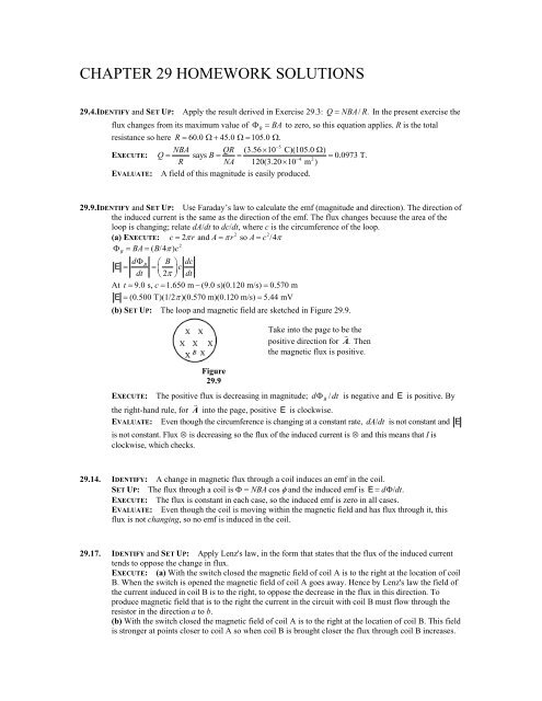
<strong>CHAPTER</strong> <strong>29</strong> <strong>HOMEWORK</strong> <strong>SOLUTIONS</strong><strong>29</strong>.4.IDENTIFY and SET UP: Apply the result derived in Exercise <strong>29</strong>.3: Q NBA/ R.In the present exercise theflux changes from its maximum value of B BA to zero, so this equation applies. R is the totalresistance so here R 60.0 45.0 105.0 .5NBA QR (3.5610 C)(105.0 )EXECUTE: Q says B 0.0973 T.4 2R NA 120(3.2010 m )EVALUATE: A field of this magnitude is easily produced.<strong>29</strong>.9.IDENTIFY and SET UP: Use Faraday’s law to calculate the emf (magnitude and direction). The direction ofthe induced current is the same as the direction of the emf. The flux changes because the area of theloop is changing; relate dA/dt to dc/dt, where c is the circumference of the loop.2 2(a) EXECUTE: c2 r and Ar so Ac /42B BA ( B/4 ) cdB B dcE cdt 2 dtAt t 9.0 s, c1.650 m (9.0 s)(0.120 m/s) 0.570 mE (0.500 T)(1/2 )(0.570 m)(0.120 m/s) 5.44 mV(b) SET UP: The loop and magnetic field are sketched in Figure <strong>29</strong>.9.Take into the page to be thepositive direction for A . Thenthe magnetic flux is positive.Figure<strong>29</strong>.9EXECUTE: The positive flux is decreasing in magnitude; d B/ dt is negative and E is positive. Bythe right-hand rule, for A into the page, positive E is clockwise.EVALUATE: Even though the circumference is changing at a constant rate, dA/dt is not constant and Eis not constant. Flux is decreasing so the flux of the induced current is and this means that I isclockwise, which checks.<strong>29</strong>.14. IDENTIFY: A change in magnetic flux through a coil induces an emf in the coil.SET UP: The flux through a coil is = NBA cos and the induced emf is E d/ dt.EXECUTE: The flux is constant in each case, so the induced emf is zero in all cases.EVALUATE: Even though the coil is moving within the magnetic field and has flux through it, thisflux is not changing, so no emf is induced in the coil.<strong>29</strong>.17. IDENTIFY and SET UP: Apply Lenz's law, in the form that states that the flux of the induced currenttends to oppose the change in flux.EXECUTE: (a) With the switch closed the magnetic field of coil A is to the right at the location of coilB. When the switch is opened the magnetic field of coil A goes away. Hence by Lenz's law the field ofthe current induced in coil B is to the right, to oppose the decrease in the flux in this direction. Toproduce magnetic field that is to the right the current in the circuit with coil B must flow through theresistor in the direction a to b.(b) With the switch closed the magnetic field of coil A is to the right at the location of coil B. This fieldis stronger at points closer to coil A so when coil B is brought closer the flux through coil B increases.
By Lenz's law the field of the induced current in coil B is to the left, to oppose the increase in flux tothe right. To produce magnetic field that is to the left the current in the circuit with coil B must flowthrough the resistor in the direction b to a.(c) With the switch closed the magnetic field of coil A is to the right at the location of coil B. Thecurrent in the circuit that includes coil A increases when R is decreased and the magnetic field of coil Aincreases when the current through the coil increases. By Lenz's law the field of the induced current incoil B is to the left, to oppose the increase in flux to the right. To produce magnetic field that is to theleft the current in the circuit with coil B must flow through the resistor in the direction b to a.EVALUATE: In parts (b) and (c) the change in the circuit causes the flux through circuit B to increaseand in part (a) it causes the flux to decrease. Therefore, the direction of the induced current is the samein parts (b) and (c) and opposite in part (a).<strong>29</strong>.20. IDENTIFY: Use the results of Example <strong>29</strong>.6. Use the three approaches specified in the problem fordetermining the direction of the induced current. I E / R.SET UP: Let A be directed into the figure, so a clockwise emf is positive.EXECUTE: (a) E vBl(5.0 m/s)(0.750 T)(1.50 m) 5.6 V(b) (i) Let q be a positive charge in the moving bar, as shown in Figure <strong>29</strong>.20a. The magnetic force on this charge is F= qvB, which points upward. This force pushes the current in a counterclockwise directionthrough the circuit.(ii) Bis positive and is increasing in magnitude, so dB/ dt 0. Then by Faraday’s law E 0 and theemf and induced current are counterclockwise.(iii) The flux through the circuit is increasing, so the induced current must cause a magnetic field out ofthe paper to oppose this increase. Hence this current must flow in a counterclockwise sense, as shown inFigure <strong>29</strong>.20b.5.6 V(c) E RI.I E 0.22 A.R 25 EVALUATE: All three methods agree on the direction of the induced current.Figure <strong>29</strong>.20B<strong>29</strong>.33. IDENTIFY: Apply Faraday’s law in the form Eav N .tSET UP: The magnetic field of a large straight solenoid is B 0nIinside the solenoid and zero2outside. B BA , where A is 8.00 cm , the cross-sectional area of the long straight solenoid.BNA( Bf Bi)NAonIEXECUTE: Eav N .t t tEav4 2 10(12)(8.0010 m )(9000 m )(0.350 A) 0.0400 s49.50 10 V.EVALUATE: An emf is induced in the second winding even though the magnetic field of the solenoidis zero at the location of the second winding. The changing magnetic field induces an electric fieldoutside the solenoid and that induced electric field produces the emf.
<strong>29</strong>.38. IDENTIFY and SET UP: Use i C q/t to calculate the charge q that the current has carried to the platesin time t. The two equations preceeding Eq.(24.2) relate q to the electric field E and the potentialdifference between the plates. The displacement current density is defined by Eq.(<strong>29</strong>.16).3EXECUTE: (a) i C1.8010 Aq 0 at t 0The amount of charge brought to the plates by the charging current in time t is3 6 10qiC t (1.8010 A)(0.50010 s) 9.0010 C10 q9.0010 C5E 2.0310 V/m12 2 2 4 2P PA(8.85410 C / N m )(5.0010 m )0 0V Ed 5 3(2.03 10 V/m)(2.00 10 m) 406 V(b) E q/P0A3dE dq / dt iC1.8010 A11 4.0710 V/m s12 2 2 4 2dt P0A P0A(8.85410 C / N m )(5.0010 m )Since i Cis constant dE/dt does not vary in time.dE(c) jD P0(Eq.(<strong>29</strong>.16)), with P replaced by P 0since there is vacuum between the plates.)dt12 2 2 11 2j D(8.85410 C / N m )(4.07 10 V/m s) 3.60 A/mi j A(3.60 A/m )(5.0010 m ) 1.8010 A; i i2 4 2 3D D D CEVALUATE: i i . C D The constant conduction current means the charge q on the plates and the electricfield between them both increase linearly with time and i Dis constant.<strong>29</strong>.45. IDENTIFY: Apply Faraday’s law and Lenz’s law.V0t/RCSET UP: For a discharging RC circuit, it () e , where V0is the initial voltage across theRcapacitor. The resistance of the small loop is (25)(0.600 m)(1.0 /m) 15.0.EXECUTE: (a) The large circuit is an RC circuit with a time constant of6 RC(10 )(2010 F) 200 s.Thus, the current as a function of time isit/200 s (100 V)/(10 ) e . At t 200 s,1 we obtain i(10 A)( e ) 3.7 A.(b) Assuming that only the long wire nearest the small loop produces an appreciable magnetic fluxthrough the small loop and referring to the solution of Exercise <strong>29</strong>.7 we obtainca0ib 0ib a B dr ln 1 .c 2r2 cTherefore, the emf induced in the small loop at t 200 s isd μ0b adiE ln1 .dt 2π cdt7 2(4π10 Wb/A m )(0.200 m) 3.7 A E ln(3.0) 0.81 mV.6Thus, the induced current in2π 20010 sthe small loop is i E 0.81 mV 54 A.R 15.0 (c) The magnetic field from the large loop is directed out of the page within the small loop.The inducedcurrent will act to oppose the decrease in flux from the large loop. Thus, the induced current flowscounterclockwise.EVALUATE: (d) Three of the wires in the large loop are too far away to make a significantcontribution to the flux in the small loop–as can be seen by comparing the distance c to the dimensionsof the large loop.
<strong>29</strong>.61. (a) and (b) IDENTIFY and Set Up:The magnetic field of the wire is given by0IB and varies along the length of the2rbar. At every point along the bar B hasdirection into the page. Divide the bar up intothin slices, as shown in Figure <strong>29</strong>.61a.Figure <strong>29</strong>.61a EXECUTE: The emf dE induced in each slice is given by dE v Bdl.v B is directed toward the 0 I wire, so dE vB dr v dr.The total emf induced in the bar is2r b dL Iv Iv 0 0 dLdr Iv0 ln( )dLVba dE dr r a d d2r2 d r 20Iv0IvV ba(ln( d L) ln( d)) ln(1 L/ d)2 2EVALUATE: The minus sign means that V bais negative, point a is at higher potential than point b. (The force F= qv B on positive charge carriers in the bar is towards a, so a is at higher potential.)The potential difference increases when I or v increase, or d decreases.(c) IDENTIFY: Use Faraday’s law to calculate the induced emf.SET UP: The wire and loop are sketched in Figure <strong>29</strong>.61b.EXECUTE: As the loop movesto the right the magnetic fluxthrough it doesn’t change. ThusdBE 0and I = 0.dtFigure <strong>29</strong>.61bEVALUATE: This result can also be understood as follows. The induced emf in section ab puts point aat higher potential; the induced emf in section dc puts point d at higher potential. If you travel aroundthe loop then these two induced emf’s sum to zero. There is no emf in the loop and hence no current.<strong>29</strong>.77. IDENTIFY: The motion of the bar produces an induced current and that results in a magnetic force onthe bar.SET UP: F Bis perpendicular to B , so is horizontal. The vertical component of the normal forceequals mg cos , so the horizontal component of the normal force equals mg tan .EXECUTE: (a) As the bar starts to slide, the flux is decreasing, so the current flows to increase theflux, which means it flows from a to b.2 2 2LB LB dBLB dA LB vL BFBiLB E B ( vLcos ) cos .At the terminal speed theR R dt R dt R R2 2vLBtRmg tan horizontal forces balance, so mg tan cosand vt 2 2 .RLB cosE 1 dB1 dA B vLBcosmgtan(c) i B ( vLcos ) .R R dt R dt R R LB2 2 22 Rm g tan (d) Pi R.2 2LB2 2 2 Rmg tanRm g tan (e) Pg Fvcos(90 ) mg sinLB2 2 and Pg .2 2 cosLBEVALUATE: The power in part (e) equals that in part (d), as is required by conservation of energy.