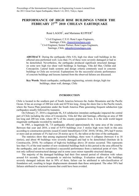
Performance of High Rise Buildings under the February 27th 2010 ...
Performance of High Rise Buildings under the February 27th 2010 ...
Performance of High Rise Buildings under the February 27th 2010 ...

You also want an ePaper? Increase the reach of your titles
YUMPU automatically turns print PDFs into web optimized ePapers that Google loves.
Type <strong>of</strong> analysis: Modal spectrum linear elastic analysis, with 5% damping and CQC modalsuperposition method. Building mass from DL + 0.25LL.Accidental Torsion Analysis: Accidental eccentricity at level k:e = ± 0.10 b (Z k / H) in each principal directionBase shear limitations: IA 0 P/6g ≤ Base shear ≤ 0.35 SIA 0 P/g for concrete buildings.If Base Shear is out <strong>of</strong> <strong>the</strong> range, forces and displacements must be scaled to <strong>the</strong> exceeded limit .Forces from <strong>the</strong> code are allowable stress level and must be amplified for 1.4 for ultimate load level.Minimum base shear for normal buildings in seismic Zone 2 is 5%P and in seismic Zone 3 is 6.7%P.Drift limitations: For stiffness and torsional plan rotation control, including accidental torsion <strong>under</strong>design spectrum forces, drift for design spectrum forces must not exceed:- Interstory drift at Center <strong>of</strong> Mass: δ cm ≤ 0.002- Interstory drift at any point i in plan: (δ cm - 0.001) ≤ δ i ≤ (δ cm + 0.001)Earthquake Load combinations: Design Spectrum forces are reduced forces that must be amplifiedfor ultimate load combinations required in ACI 318. Load combinations are:1.4 (DL + LL ± E)0.9 DL ± 1.4 ESeismic Zoning:Seismic Zone Geographic Area A 0Zone 1 Andes Mountains strip area 0.20 gZone 2Central strip <strong>of</strong> Chile between <strong>the</strong> Coastal0.30 gMountains and <strong>the</strong> Andes MountainsZone 3 Costal strip area 0.40 gTypes <strong>of</strong> foundation soils:Soil Type Description S T 0 T’ n pI Rock 0.90 0.15 0.20 1.00 2.0II Dense gravel, and soil with vs ≥ 400 m/s in upper 10 m. 1.00 0.30 0.35 1.33 1.5III Unsaturated Gravel and sand with low compaction 1.20 0.75 0.85 1.80 1.0IV Saturated cohesive soil with q u < 0.050 Mpa 1.30 1.20 1.35 1.80 1.0Building Category: Importance factorBuildingCategoryDescriptionIA Governmental, municipal, public service or public use 1.2B <strong>Buildings</strong> with content <strong>of</strong> great value or with a great number <strong>of</strong> people. 1.2C <strong>Buildings</strong> not included in Category A or B 1.0D Provisional structures not intended for living 0.6Design Spectrum: (fig. 1)Parameter Formula CommentsDesign SpectrumSaI AoR * I : importance factorA 0 : zone maximum effective accelerationR*: reduction factorα : amplification factor1756
Fig. 3 Typical residential buildingFig. 4 Typical <strong>of</strong>fice buildingAt <strong>the</strong> conceptual stage, historical practice in Chile indicates that structural engineers, when allowedby architectural requirements, selectively turn partitions into structural wall with <strong>the</strong> following simplecriteria:• Assuming <strong>the</strong> building has an average unit weight per floor area <strong>of</strong> 10 KPa (1.0 ton/m 2 ), <strong>the</strong> wallarea in each principal direction at <strong>the</strong> base floor level, divided by <strong>the</strong> total floor area above (walldensity), must be larger than 0.001. The reason for this comes from an historical code minimumbase shear <strong>of</strong> 6%P, and a conservative average shear stress below 0.6 MPa (6.0 kg/cm 2 ), not in <strong>the</strong>code. This criterion also implicitly limits <strong>the</strong> average compression in walls to a value less than 5.0MPa (50 kg/cm 2 ).• The distribution <strong>of</strong> walls in plan must be as uniform as possible, generating slabs <strong>of</strong> similar sizes,placing some <strong>of</strong> <strong>the</strong> walls at <strong>the</strong> perimeter for building torsional stiffness.The usual procedure among <strong>the</strong> local structural engineers for <strong>the</strong> definition and fine-tuning <strong>of</strong> <strong>the</strong>structural system <strong>of</strong> a high-rise building after selecting <strong>the</strong> first array <strong>of</strong> walls has been:• Perform a preliminary response spectrum analysis (RSA) scaled to minimum base shear.• Verification <strong>of</strong> compliance <strong>of</strong> <strong>the</strong> story drift limit at <strong>the</strong> center <strong>of</strong> mass (CM) at every floor.Usually with <strong>the</strong> suggested wall density this restriction is immediately achieved.• Scheck for <strong>the</strong> story drift limitation at <strong>the</strong> perimeter to be within <strong>the</strong> codes requirement <strong>of</strong> 0.001from <strong>the</strong> CM. Normally it requires <strong>the</strong> addition <strong>of</strong> a perimeter frame formed by properlyconnecting piers with <strong>the</strong> upturned-beams as spandrels.• Fine-tune <strong>the</strong> wall thickness <strong>of</strong> each wall along <strong>the</strong> height to comply with <strong>the</strong> desired shear stress.These simple rules have configured what has been called <strong>the</strong> typical Chilean RC building.Aw/Af (x10 -2 )987654321DataTrenddnp (x10 -3 ) [m 2 /ton]1412108642DataTrend01937 1947 1957 1967 1977 1987 1997 2007YearFig. 5 Wall Area / Floor Area at first storyStructural Indicators01937 1947 1957 1967 1977 1987 1997 2007YearFig. 6 Wall Area / Total Weight above first story1758
Several indicators have been widely used throughout <strong>the</strong> years in Chile to evaluate <strong>the</strong> structuralcharacteristics <strong>of</strong> concrete buildings, with <strong>the</strong> intent to find a correlation between general structuralconception and successful seismic performance. The indicators presented are related only to globalresponse <strong>of</strong> buildings <strong>under</strong> earthquake loads and not to <strong>the</strong> behavior <strong>of</strong> individual elements. Toachieve a successful performance strategy, <strong>the</strong> adoption <strong>of</strong> an adequate general structural system mustbe properly complemented with <strong>the</strong> adoption <strong>of</strong> capacity design principles for <strong>the</strong> design and detailing<strong>of</strong> individual elements. The Macro approach is <strong>the</strong> definition <strong>of</strong> <strong>the</strong> global system, and <strong>the</strong> Microapproach are <strong>the</strong> principles behind <strong>the</strong> detailing <strong>of</strong> individual elements. They must be consistent withobjectives that define a successful seismic performance.Wall Density Indicator d np :Figure 5 shows <strong>the</strong> wall area in <strong>the</strong> first floor on each principal direction divided by <strong>the</strong> floor area <strong>of</strong>that floor, without consideration <strong>of</strong> <strong>the</strong> number <strong>of</strong> floors above. This ratio remains constant in timewith values in <strong>the</strong> range <strong>of</strong> 2-4%. Figure 6 illustrate <strong>the</strong> evolution <strong>of</strong> <strong>the</strong> Wall Density parameter d np .This parameter calculated as <strong>the</strong> wall area in <strong>the</strong> first floor on each principal direction divided by <strong>the</strong>total weight <strong>of</strong> <strong>the</strong> floor area above this level with units <strong>of</strong> (m 2 /ton), (Gómez 2001 & Calderón 2007).In <strong>the</strong> last 60 years <strong>the</strong>re has been trend to a continuous reduction <strong>of</strong> <strong>the</strong> average wall densityindicator. Never<strong>the</strong>less a constant minimum <strong>of</strong> 0.001 is observed. This is consistent with <strong>the</strong> basiccriteria, described previously, for <strong>the</strong> determination <strong>of</strong> <strong>the</strong> wall area required in each principaldirection, assuming a unit weight per floor area <strong>of</strong> 10 KPa (1.0 ton/m 2 ).The inverse <strong>of</strong> this indicator has units <strong>of</strong> MPa (ton/m 2 ) and is directly related with <strong>the</strong> averagecompression forces and <strong>the</strong> seismic shear forces acting on <strong>the</strong> walls. A decreased value <strong>of</strong> <strong>the</strong> walldensity indicator implies a direct increase in wall compression and shear stresses. The use <strong>of</strong>sophisticated structural analysis s<strong>of</strong>tware and <strong>the</strong> use <strong>of</strong> higher strength concrete have led to <strong>the</strong> use <strong>of</strong>relatively thin walls, resulting in brittle behavior and poor performance when subjected to large lateraldisplacements. Different authors have demonstrated (Massone, 2011) that <strong>the</strong> maximum ro<strong>of</strong> lateraldisplacement is dependent <strong>of</strong> <strong>the</strong> relation c/l w that is directly related with <strong>the</strong> axial load, <strong>the</strong> geometryand reinforcing <strong>of</strong> <strong>the</strong> wall. Walls with L or T shape and setbacks are especially vulnerable to thissituation due to large compression stresses at <strong>the</strong> web when subjected to large lateral displacements.Evidence shows that an important percentage <strong>of</strong> <strong>the</strong> damaged walls fall in this category. This type <strong>of</strong>situation is usually present in modern buildings below ground level where larger spaces for parkingfacilities are needed.Wall density values above 0.001m 2 /ton in each principal direction have proven to provideadequate earthquake behavior when properly designed. It becomes evident that design <strong>of</strong> shear wallsmust follow capacity design principles to provide an individual ductile behavior in order to guaranteea global successful behavior for <strong>the</strong> building <strong>under</strong> large lateral displacements. General practice, withsome exceptions, prior to 2008 did not follow <strong>the</strong>se principles due to <strong>the</strong> Chilean code exclusion <strong>of</strong> <strong>the</strong>ACI 318 requirement for transverse reinforcement in boundary elements in walls. This made wallsvulnerable when subjected to large displacements such as <strong>the</strong> observed on s<strong>of</strong>t soils in Concepción,Viña del Mar and Santiago.Stiffness Indicator H / T:Proposed by Guendelman (2000) it is <strong>the</strong> quotient <strong>of</strong> <strong>the</strong> Total Height <strong>of</strong> <strong>the</strong> building (H) divided by<strong>the</strong> First Translational mode period <strong>of</strong> <strong>the</strong> building calculated from spectral analysis (T). The unitsare meters/sec. which represents a velocity. Figure 7 show historical values from a database <strong>of</strong> 2622Chilean buildings (Guendelman, <strong>2010</strong>). Values <strong>of</strong> H/T are in <strong>the</strong> range <strong>of</strong> 20 – 160 m/sec. Valuesbelow 40 m/sec. apply to flexible mostly frame buildings; values between 40 and 70 m/sec. representnormal stiffness buildings and values over 70 m/sec. pertain to stiff buildings.Historically, Chilean buildings can be classified in <strong>the</strong> range <strong>of</strong> stiff to normal according to <strong>the</strong>stiffness indicator.1759
Fig. 7 Stiffness Indicator = H/T (Guendelman, <strong>2010</strong>)Top Level Drift for δ u =1.3 S de (Soil Type II)2622 Chilean <strong>Buildings</strong> Database by GuendelmanFig. 8 <strong>Performance</strong> Indicator: (Top displacement δ u /H) / vs. H/T parameter. (Guendelman, <strong>2010</strong>)<strong>Performance</strong> Indicator δ u / H:The <strong>Performance</strong> indicator is <strong>the</strong> top level drift (relative to ground level) evaluated according tocurrent post earthquake version <strong>of</strong> <strong>the</strong> Chilean code NCh433 established in DS61 MINVU 2011. TheMaximum Lateral Displacement <strong>of</strong> <strong>the</strong> ro<strong>of</strong> δ u is calculated as 1.3 times <strong>the</strong> Elastic DisplacementSpectrum at <strong>the</strong> top S de for <strong>the</strong> cracked translational period with <strong>the</strong> largest mass participation factor inthat direction. This value can be assumed as <strong>the</strong> ro<strong>of</strong> displacement for <strong>the</strong> Deterministic MaximumConsidered Earthquake (MCE). Figure 8 illustrate <strong>the</strong> <strong>Performance</strong> Parameter δ u / H vs. <strong>the</strong> parameterH/T. In <strong>the</strong> graphic, 88% <strong>of</strong> <strong>the</strong> buildings have drift values bellow 0.005 which according to Vision2000 <strong>Performance</strong> Objectives, this represents operational behavior, and 54% have drift values bellow0.002 which represent a performance objective <strong>of</strong> service behavior. Less than 2% have drift valuesabove 0.01. It can be noticed that this value is similar to <strong>the</strong> percentage <strong>of</strong> building failures reported1760
during <strong>the</strong> Maule earthquake.Figure 8 also illustrate that stiff buildings evaluated <strong>under</strong> <strong>the</strong> parameter H/T have a better globalbehavior than low stiffness systems according to performance objectives defined in SAOC VISION2000. This comparison favors <strong>the</strong> adoption <strong>of</strong> shear wall type systems instead <strong>of</strong> frame type systems asa strategy for increased earthquake performance in high-rise buildings and is consistent with <strong>the</strong>historical Chilean practice.Ductility Demand Indicator or Effective Spectral Reduction Factor R**:R** = Elastic Response Base Shear / 1.4 Design Response Base ShearFigure 9 illustrate code values for <strong>the</strong> reduction factor R* multiplied by a factor 1.4 for ultimateload level, and <strong>the</strong> impact <strong>of</strong> <strong>the</strong> incorporation <strong>of</strong> <strong>the</strong> minimum base shear requirement that turns R*into R 1 for a single degree <strong>of</strong> freedom system (1-DOF).The Ductility Demand indicator R** is evaluated for a database <strong>of</strong> 1280 buildings in zone 2, soiltype 2 and for 115 buildings in zone 3, soil type II (designed by René Lagos Engineers). The trendshows that for buildings with natural periods above 1.5 sec. values for <strong>the</strong> ductility demand are in <strong>the</strong>range <strong>of</strong> 1 to 4. For buildings with natural periods around 0.5 sec., <strong>the</strong> zone where minimum baseshear starts to control design, <strong>the</strong> ductility demand indicator has <strong>the</strong> highest values, in <strong>the</strong> range <strong>of</strong> 4 to5.5. This correlates with <strong>the</strong> evidence that shows that <strong>the</strong> majority <strong>of</strong> <strong>the</strong> damaged buildings had <strong>the</strong>irfirst natural period around 0.6 seconds. It also shows <strong>the</strong> importance <strong>of</strong> <strong>the</strong> use <strong>of</strong> capacity design andductility principles in <strong>the</strong> design and detailing <strong>of</strong> walls.Fig. 9 Ductility Demand Indicator R** for 1280 buildings in zone 2, soil type II, and for 115 buildingsin zone 3, soil type II (Database from René Lagos Engineers).Required Displacement Ductility Ratio Indicator µ Δ *:µ Δ * = δ u / 1.4 ro<strong>of</strong> design displacement according to NCh433.Of96The Required Displacement Ductility Ratio Indicator µ Δ * is evaluated for a database <strong>of</strong> 1280buildings in zone 2, soil type 2 and for 96 buildings in zone 3, soil type III (designed by René LagosEngineers). Figure 10 shows that buildings with natural periods above 1.5 sec. have values for <strong>the</strong>displacement ductility demand ratio below 3. For buildings with natural periods below 0.5 sec., <strong>the</strong>displacement ductility demand ratio increases rapidly (with a large dispersion) as <strong>the</strong> period decreases,presenting values in <strong>the</strong> range 2 to 8. The existence <strong>of</strong> values around 2 in all <strong>the</strong> range <strong>of</strong> periodsevaluated suggest that <strong>the</strong> natural period is not an appropriate parameter for <strong>the</strong> evaluation <strong>of</strong> <strong>the</strong>displacement ductility demand ratio, regardless <strong>the</strong> observed tendency that average values <strong>of</strong> µ Δ *decrease for increasing values <strong>of</strong> T(sec). Studies to evaluate how <strong>the</strong> indicator µ Δ * varies with <strong>the</strong>parameter H/T are in progress in order to evaluate <strong>the</strong> influence <strong>of</strong> <strong>the</strong> lateral load structural system on<strong>the</strong> indicator.Figure 10 also shows <strong>the</strong> importance <strong>of</strong> <strong>the</strong> use <strong>of</strong> capacity design and ductility principles in <strong>the</strong> design1761
and detailing <strong>of</strong> walls.Fig. 10 Required Displacement Ductility Ratio Indicator µ Δ * for 1280 buildings in zone 2, soil type II,and for 96 buildings in zone 3, soil type III (Database from René Lagos Engineers).DAMAGE IN RC BUILDINGS IN CONCEPCION AND VIÑA DEL MARAFTER THE <strong>2010</strong> EARTHQUAKE IN CHILEThe earthquake presented some unexpected characteristics such as <strong>the</strong> low frequency content, not seenbefore in Chile. This affected considerably <strong>the</strong> response <strong>of</strong> high rise buildings. Records obtained inConcepción by <strong>the</strong> University <strong>of</strong> Chile (Boroschek, <strong>2010</strong>) show high destructive potential and aresimilar to o<strong>the</strong>rs obtained in Viña del Mar and Santiago in s<strong>of</strong>t soils (figure 10).Fig. 10 Response spectra at 5% percent damping for records obtained in zone 3 and soil type IIaccording to Chilean seismic codes. Elastic demands <strong>of</strong> NCh433, NCh2369 and NCh2745 are shown.A) Acceleration Spectra. B) Displacement Spectra.The earthquake produced important structural damage in a number <strong>of</strong> high rise shear wallbuildings in Santiago, Viña del Mar, Chillán and Concepción. Damage was concentrated at <strong>the</strong> base,on L or T shape walls with compression failures and buckling in vertical reinforcement at poorlydetailed boundary elements. Shear failures at <strong>the</strong> web were also observed.Figures 11 and 12 show typical plan configurations <strong>of</strong> damaged buildings (Bonelli, <strong>2010</strong>). Thearchitecture <strong>of</strong> this buildings present similar characteristics such as a central corridor with transversewalls <strong>of</strong> rectangular L or T shape. The walls are continuous from top to foundation. At street and<strong>under</strong>ground parking levels <strong>the</strong> walls frequently present penetrations or length reduction to facilitateparking. This represents a common structural irregularity on modern high rise buildings.1762
Fig. 11 Building B, Concepcion: Compression, tension and shear failure on first and second floorsFig. 12 Building C, Viña del Mar: general wall failure at first floor: 40 cm out <strong>of</strong> plumb at <strong>the</strong> top.CHILEAN CODE CHANGES AFTER THE <strong>2010</strong> EARTHQUAKEAfter <strong>the</strong> <strong>2010</strong> Maule Earthquake, changes have been made to <strong>the</strong> codes through governmentadministrative procedures established in DS60 MINVU 2011 for <strong>the</strong> Design <strong>of</strong> RC <strong>Buildings</strong> and <strong>the</strong>DS61 MINVU 2011 for <strong>the</strong> Seismic Design <strong>of</strong> <strong>Buildings</strong>.NCh433 changes introduced by DS61 MINVU 2011 for <strong>the</strong> Seismic Design <strong>of</strong> <strong>Buildings</strong>:• A new soil type classification is introduced defining soils types A, B, C, D and F, renaming soiltype I as A, II as B, a new type C, III as D and a new type F.• The existing pseudo-acceleration spectrum is multiplied by a new parameter S, dependent <strong>of</strong> <strong>the</strong>soil, with values 0.9 for soil type A, 1.0 for soil B, 1.05 for soil C, 1.20 for soil D and 1.30 for soilE. Soil type F, requires a site assessment <strong>of</strong> seismic hazard.• A new Elastic Displacement Response Spectra S de is introduced.The parameter C* d is dependent <strong>of</strong> <strong>the</strong> soil type and <strong>the</strong> natural period <strong>of</strong> <strong>the</strong> building, havingvalues larger than 1.0 for calibration with <strong>the</strong> observed displacements in real buildings <strong>under</strong> <strong>the</strong><strong>February</strong> 27 th <strong>2010</strong> earthquake. Conceptually this spectrum corresponds to a more severeearthquake than <strong>the</strong> assumed for <strong>the</strong> respective pseudo-acceleration spectrum in <strong>the</strong> code.• For concrete buildings, <strong>the</strong> Maximum Lateral Displacement at <strong>the</strong> ro<strong>of</strong> <strong>of</strong> <strong>the</strong> building δ u isdefined. This is calculated as 1.3 times <strong>the</strong> value <strong>of</strong> <strong>the</strong> Elastic Displacement Response Spectrum1763
at <strong>the</strong> top S de for <strong>the</strong> cracked translational period with <strong>the</strong> largest mass participation factor in thatdirection, for 5% <strong>of</strong> critical damping. This value can be assumed as <strong>the</strong> ro<strong>of</strong> displacement for <strong>the</strong>Deterministic Maximum Considered Earthquake (MCE).NCh430 changes introduced by DS60 MINVU2011 for <strong>the</strong> design <strong>of</strong> RC buildings:Adoption <strong>of</strong> ACI 318-08 provisions with some minor exceptions for <strong>the</strong> design <strong>of</strong> concrete specialstructural walls. These provisions are intended to prevent crushing and spalling <strong>of</strong> concrete andbuckling <strong>of</strong> vertical reinforcement at boundary regions by providing a ductile behavior to individualwalls and placing a limit <strong>of</strong> 0.008 to <strong>the</strong> maximum compression strains when <strong>the</strong> building reaches <strong>the</strong>Maximum Lateral Displacement at <strong>the</strong> ro<strong>of</strong> δ u .The use <strong>of</strong> capacity design has been incorporated to prevent shear failures.The most important changes for <strong>the</strong> design for bending and axial load <strong>of</strong> shear walls are:• The level <strong>of</strong> axial stress allowed:An explicit limit is established for <strong>the</strong> maximum value <strong>of</strong>: P u ≤ 0.35f’ cAn implicit limit is established by requiring that <strong>the</strong> maximum concrete compression strains e c at<strong>the</strong> critic zone in walls must not exceed 0.008 when <strong>the</strong> Maximum Lateral Displacement at <strong>the</strong>ro<strong>of</strong> δ u occurs. This requirement also limits compression damage in <strong>the</strong> wall at <strong>the</strong> MCE.• Slenderness: wall thickness must be greater than 1/16 <strong>of</strong> <strong>the</strong> unbraced length.• Splices in longitudinal reinforcement: transverse reinforcement must be provided at lap splices.• Bar buckling: spacing <strong>of</strong> transverse reinforcement must be ≤ 6 longitudinal bar diameter.CONCLUSIONS<strong>High</strong> rise concrete buildings constructed in Chile in <strong>the</strong> past 25 years performed well during <strong>the</strong> <strong>2010</strong>earthquake. Never<strong>the</strong>less, <strong>the</strong> earthquake produced significant structural damage on some new midriseshear wall buildings never seen on previous earthquakes.The level <strong>of</strong> performance observed for <strong>the</strong> majority <strong>of</strong> RC high-rise buildings designed accordingto modern codes such as <strong>the</strong> ACI 318 was successful when <strong>the</strong> seismic code provided a reasonableestimate <strong>of</strong> <strong>the</strong> displacement demand.The historical Chilean practice <strong>of</strong> using high density shear wall lateral load systems instead <strong>of</strong>frame type systems has favored <strong>the</strong> good global performance <strong>of</strong> high-rise buildings during <strong>the</strong> Mauleearthquake.The parameter H/T has a good correlation with <strong>the</strong> performance objectives defined as δu/Haccording to SAOC VISION 2000. In buildings with values <strong>of</strong> H/T > 70 studies indicate that globalelastic response could be expected in firm soils, never<strong>the</strong>less at individual elements level, inelasticbehavior may occur. To take advantage <strong>of</strong> a well-conceived lateral load system, <strong>the</strong> design anddetailing <strong>of</strong> individual elements must be done following capacity design and ductility principles.Recognizing that <strong>the</strong> building performance is governed by displacement demand ra<strong>the</strong>r thanstrength, <strong>the</strong> codes NCh433.Of96 drift limitations <strong>under</strong> reduced design forces with a minimum baseshear, led to <strong>the</strong> adoption <strong>of</strong> stiff lateral structural systems with high values <strong>of</strong> H/T. This indirectlycontributed to <strong>the</strong> successful performance <strong>of</strong> high-rise buildings observed during <strong>the</strong> <strong>2010</strong> earthquake.The new provisions introduced in <strong>the</strong> Chilean Codes after <strong>the</strong> earthquake, represent an importantstep in <strong>the</strong> performance and <strong>the</strong> damage control objectives. These provisions are intended to preventcrushing and spalling <strong>of</strong> concrete and buckling <strong>of</strong> vertical reinforcement at boundary regions, and at<strong>the</strong> same time prevent shear failures when <strong>the</strong> buildings are subjected to large displacement demands.1764
REFERENCESAmerican Concrete Institute (2005), Building Code Requirements for Structural Concrete (ACI318-05) and Commentary (318R-05), Farmington Hills, MI., 2005, 430pp.American Society <strong>of</strong> Civil Engineers (<strong>2010</strong>). ASCE/SAI 7-10: Minimum Design Loads for<strong>Buildings</strong> and O<strong>the</strong>r Structures, Reston, Va., 650pp.Bonelli P., <strong>2010</strong>. Evaluación de Daños y Normativa Terremoto en Chile Central-<strong>2010</strong> (inSpanish), Presentación Congreso ACHISINA, Santiago Chile <strong>2010</strong>.Boroschek R., Soto P., and Leon R., <strong>2010</strong>. Registros del Terremoto del Maule Mw=8.8 27 deFebrero de <strong>2010</strong>, Red Nacional de Acelerógrafos del Departamento de Ingeniería Civil,Facultad de Ciencias y Matemáticas, Universidad de Chile, Informe RENADIC 10/05,100pp. (p://www.terremotosuchile.cl/)Calderón JA, 2007. Update on Structural System Characteristic used in RC BuildingConstruction in Chile (in Spanish), Civil Engineering Thesis, University <strong>of</strong> Chile, 76 pp.Comisión de Diseño Estructural en Hormigón Armado y Albañilería, Edificios Chilenos de HormigónArmado, Cámara Chilena de la Construcción, pp. 117, June 2002Comité Inmobiliario (real state committee). CChC, <strong>2010</strong>. Communication based on INE data,Instituto Nacional de Estadisticas (National Institute <strong>of</strong> Statistics), http://www.ine.cl/D.S. Nº 60 MINVU (2011), Reglamento que fija los requisitos de diseño y cálculo para el hormigónarmado y deroga Decreto Nº 118, de <strong>2010</strong> (in Spanish), Ministerio de Vivienda y Urbanismo.Diario Oficial 13 de Diciembre del 2011D.S. Nº 61 MINVU (2011), Reglamento que fija el diseño sísmico de edificios y deroga Decreto Nº117, de <strong>2010</strong> (in Spanish), Ministerio de Vivienda y Urbanismo. Diario Oficial 13 de Diciembredel 2011Gómez C.E., 2001. Structural System Characteristics used in RC and Reinforced MasonryBuilding Construction in Chile (in Spanish), Civil Engineering Thesis, University <strong>of</strong> Chile.GUC seismological services at <strong>the</strong> University <strong>of</strong> Chile, http://www.sismologia.cl/Instituto de la Construcción, Comisión Provisoria Terremoto <strong>2010</strong>, 30 Propuestas relativas alterremoto 27-F <strong>2010</strong> (in Spanish), Anexo 2, March <strong>2010</strong>Guendelman T., Lindenberg J., Perfil bio-sísmico de edificios. Un instrumento de calificación sísmica(in Spanish), Revista BIT, v.7:n.17, pp.33, March 2000Guendelman T., Lindenberg J., Cambio en Dolicitaciones Sísmicsd en Edificios, Seminario Efectosdel Terremoto en el Nuevo Diseño Sísmico y Estructural en Chile, ICH Nov. <strong>2010</strong>.Massone L, Bonelli P, Lagos R, Lüder C, Wallace JW, 2011, RC Building Damage and CodeImplications, EERI, Earthquake Spectra – Chile Special Issues.Official Chilean Standard, NCh433.Of96, Earthquake Resistant Design <strong>of</strong> <strong>Buildings</strong> (in English),Instituto Nacional de Normalización, INN, 43pp, 1996Official Chilean Standard, NCh430.Of2008, Reinforced Concrete – Design and calculationrequirements (in Spanish), Instituto Nacional de Normalización, INN, 17pp., 2008Official Chilean Standard, NCh2745.Of03, Analysis and Design <strong>of</strong> <strong>Buildings</strong> with Base Isolation (inSpanish)), Instituto Nacional de Normalización, INN, 98pp, 2003Official Chilean Standard, NCh2369.Of03, Earthquake Resistant Design <strong>of</strong> Industrial Structures andFacilities (in Spanish)), Instituto Nacional de Normalización, INN, 120pp, 2003Structural Engineers Association <strong>of</strong> California, <strong>Performance</strong> Based Seismic Engineering <strong>of</strong> <strong>Buildings</strong>VISION2000, 1995.1765