XP DI - Sea-Doo.net
XP DI - Sea-Doo.net
XP DI - Sea-Doo.net
- No tags were found...

You also want an ePaper? Increase the reach of your titles
YUMPU automatically turns print PDFs into web optimized ePapers that Google loves.
SAFETY WARNINGDisregarding any of the safety precautions and instructions contained in thisOperator’s Guide, the Safety Handbook, the Safety Videocassette and on theon-product warning labels could cause injury, including the possibility ofdeath. The operator has the responsibility to inform passenger(s) of safetyprecautions.This Operator’s Guide, the Safety Handbook and Safety Videocassetteshould remain with the craft at the time of resale.DECLARATIONOF CONFORMITY2003 PWC Electro Mag<strong>net</strong>ic Compatibility (EMC)Compliance with 93/68 EC Directive.The 2003 <strong>Sea</strong>-<strong>Doo</strong> Personal Watercraft do comply with the above mentioneddirective and with 89/336 EC directive in order to match the currentEuropean requirements on Personal Watercraft (PWC).Knight’s Spray-Nine † is a trademark of Korkay System LtdGTX † is a trademark of Castrol Ltd. Used under licenseThe following trademarks are the property of Bombardier Inc. or itssubsidiaries:SEA-DOO ®BOMBAR<strong>DI</strong>ER-ROTAX ®BOMBAR<strong>DI</strong>ER LUBE ®BOMBAR<strong>DI</strong>ER Formula <strong>XP</strong>-S II Synthetic Injection Oil<strong>Sea</strong>-<strong>Doo</strong> LK TMRotax ®Printed in Canada (smo2003-004a.fm SH)®*Trademarks of Bombardier Inc. and/or its subsidiaries.©2002 Bombardier Inc. All rights reserved.
NOTEDear 2003 <strong>XP</strong> <strong>DI</strong> watercraft owner. Use the information pertaining to the RX<strong>DI</strong> model in the 2003 Operator’s Guide (P/N 219 000 290) and then use thissupplement to complete the specific information that applies to your <strong>XP</strong> <strong>DI</strong>model.1
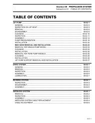
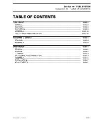
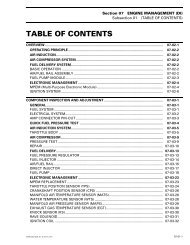
TABLE OF CONTENTSLOCATION OF THE IMPORTANT LABELS ................................... 3LOCATION OF CONTROLS, COMPONENTS AND INSTRUMENTS . 6FUNCTIONS OF CONTROLS, COMPONENTS AN<strong>DI</strong>NSTRUMENTS ........................................................................... 815) Oil Injection Reservoir Cap................................................................ 816) Front Storage Compartment Cover ................................................... 826) Mooring Cleats .................................................................................. 937) Fuses ................................................................................................. 938) Battery ............................................................................................... 941) Storage Compartment/Engine Cover Latches ................................... 942) Rear Access Cover ............................................................................ 943) Automatic Bilge Pump....................................................................... 9OPERATING INSTRUCTIONS ...................................................... 10SPECIAL PROCEDURES.............................................................. 12Towing the Watercraft in Water .............................................................. 12MAINTENANCE .......................................................................... 13Lubrication ............................................................................................... 13Periodic Inspection Chart......................................................................... 13Fuses ....................................................................................................... 14TRAILERING, STORAGE AND PRE-SEASON PREPARATION....... 16Storage .................................................................................................... 16SPECIFICATIONS........................................................................ 212
LOCATION OF THE IMPORTANT LABELS<strong>XP</strong> <strong>DI</strong> Models8 43-52912F08L1ULTYPICAL3
Label 14F08A04L
<strong>XP</strong> <strong>DI</strong> Model OnlyThe location of these labels differ onthe <strong>XP</strong> <strong>DI</strong> model.Label 5Label 2F00A23YLabel 8F00A22YLabel 3F00A27YF02L2D0Label 9Label 4F00A1AYLabel 12F00L29YF08G04YF00L2XY5
LOCATION OF CONTROLS, COMPONENTS AN<strong>DI</strong>NSTRUMENTS<strong>XP</strong> <strong>DI</strong> Model16192342264341261815373814TYPICALNOTE: Components not shown here are the same as on the RX <strong>DI</strong> models inthe 2003 <strong>Sea</strong>-<strong>Doo</strong> Operator’s Guide.6F08L1WL
14) Fuel Tank Cap15) Oil Injection Reservoir Cap16) Front Storage Compartment Cover18) Tool Kit19) Air Intake Opening23) Rear Grab Handle26) Mooring Cleats37) Fuses38) Battery41) Storage Compartment/Engine Cover Latches42) Rear Access Cover43) Automatic Bilge PumpNOTE: Some components shown in the 2003 <strong>Sea</strong>-<strong>Doo</strong> Operator’s Guide do notapply to this watercraft. Refer to the following list:7) Shift Lever8) Fuel Gauge/Low Oil Warning Light10) Tachometer13) Fuel Tank Valve17) Front Storage Compartment Cover Latch20) <strong>Sea</strong>t Strap21) <strong>Sea</strong>t Latch22) <strong>Sea</strong>t Extension Latch24) Rear Storage Basket30) Boarding Step35) Reverse Gate39) Side Vanes7
FUNCTIONS OF CONTROLS, COMPONENTSAND INSTRUMENTSThe following components have thesame operation as explained in the2003 Operator’s Guide, only their locationdiffer. To know where they are located,refer to the LOCATION OFCONTROLS, COMPONENTS AND IN-STRUMENTS section in the previouspages.14) Fuel Tank Cap18) Tool Kit19) Air Intake Opening23) Rear Grab HandleThe following components are specificto the <strong>XP</strong> <strong>DI</strong> models. Refer to the followingupdated texts and/or illustrations.15) Oil Injection ReservoirCapOpen engine cover and remove storagetray.1F08G04YReinstall cap and fully tighten it. WARNINGDo not overfill. Never exceed theMAX. oil level line. Reinstall capand fully tighten. Oil is inflammable.Always wipe off any oil spillagefrom the bilge.16) Front StorageCompartment CoverIt gives access to the front storage compartment.Always relatch cover afterclosing.The tray is provided with separatecompartments.12F08L0VZTYPICAL1. Oil injection reservoir capTo add injection oil in the reservoir, unscrewthe cap counterclockwise.Do not overfill. Make sure oil leveldoes not exceed the level shown onthe following drawing. Otherwise, siphonout the extra oil. Do not operatethe engine when oil level exceeds therecommendation.F08L0UY1. Fire extinguisher (sold separately)2. Retaining strap8
WARNINGEnsure to properly secure extinguisherwith the supplied retainingstraps.26) Mooring CleatsAll ModelsThese cleats can be temporarily used fordocking, while refueling for example.CAUTION: Never use mooring cleatsto pull or lift the watercraft.42) Rear Access CoverIt gives access to the battery, drivesystem, suspension, exhaust systemand bailer pick-ups. Always relatchcover.43) Automatic Bilge PumpBilge pump evacuates water from thebilge.When safety lanyard cap is installed onits post, bilge pump automaticallyturns on. It will remain on until all wateris evacuated, if any, then it will shutdown automatically.When engine is running, bilge pumpwill automatically start periodically toevacuate water.F08L0TZ 11. Mooring cleats37) FusesFuses are located in engine compartment.Refer to MAINTENANCE formore details.38) BatteryBattery is located in bilge under seat.Refer to SPECIAL PROCEDURES.41) Storage Compartment/Engine Cover LatchesPull both latch levers upward in order toopen the storage compartment/enginecover. Always relatch cover on bothsides.NOTE: Verify periodically the lock pinstightness. Tighten if needed and makesure storage compartment/engine coverlatches properly.9
OPERATING INSTRUCTIONSVariable Trim SystemThe variable trim system (VTS) changesthe angle of the jet pump nozzle toprovide the operator with a fast, effectivesystem to compensate for load,thrust, riding position and water conditions.Correctly adjusted, it can improvehandling, reduce porpoising, andposition the watercraft at its best ridingangle to attain maximum performance.When first using the watercraft, theoperator should become familiar withthe use of the variable trim system(VTS) at varying speeds and water conditions.A mid-range trim is generallyused when cruising. Experience alonewill dictate the best trim for the conditions.During the watercraft break-inperiod, when lower speeds are recommended,it is an excellent opportunityto gain familiarity of trim adjustmentand its effects.When the nozzle is positioned in an upwardangle, the water thrust directs thebow of the watercraft upward. This positionis used to optimize high speed.2F08J0AYTYPICAL1. Push on arrow pointing upward on VTSbutton2. Bow up3. Nozzle up318°10
128°F08J0BY3TYPICAL1. Push on arrow pointing downward on VTSbutton2. Bow down3. Nozzle down11
SPECIAL PROCEDURESTowing the Watercraft inWaterIt is the same as explained in the 2003Operator’s Guide. The hose locationand routing differs. Refer to the followingupdated text and illustration.Remove rear access cover.Install pincher as shown.1F08E08Y1. Hose pincher on water supply hoseProperly relatch cover.CAUTION: When finished towing thewatercraft, hose pincher should beremoved before operating it. Failureto do so will result in damage to theengine.12
MAINTENANCELubrication<strong>Sea</strong>l CarrierUsing a grease gun, carefully lubricateseal carrier of mid bearing until greaseis just coming out of seal.1F08E0BY1. Grease seal carrier of mid bearingPeriodic Inspection ChartThe following is to be added for the <strong>XP</strong> <strong>DI</strong> models.DESCRIPTIONFREQUENCYI: Inspect, verify, clean, adjust, lubricate,replace if necessaryC: CleanL: LubricateR: ReplaceFIRST 10HOURSEVERY 25HOURS OR3 MONTHSEVERY 50HOURS OR6 MONTHSEVERY 100HOURSOR 1 YEARTO BEPERFORMEDBYPROPULSIONSYSTEMPTO flywheel and seal carrier L LOPERATOR13
FusesRefer to this updated text and illustrations.Fuses can be found at 2 locations; onthe MPEM and in the electrical box.MPEMTo access fuses on the MPEM, openfront storage compartment cover andremove storage tray.Locate MPEM on the left side of watercraft.F08H0JY1. MPEMFuses are identified, look above andbesides the fuse holder.1F18H06Y2 1F1 : FP 15AF2 : ACC 2AF3 : REG 25AF4 : VTS 7.5AF5 : BAT 25AF6 : INJ 15AFUSE IDENTIFICATION1. Fuse identification2. Fuse descriptionF1 F2 F3 F4 F5 F6Fuse identification: The fuses (F) areidentified from 1 to 6.Fuse description: The fuses are describedwith abbreviation as follows:FP: Fuel pumpACC: Accessories (information center)REG: Regulator (charging system)VTS: Variable Trim SystemBAT: BatteryINJ: Injection systemThe fuse description is followed by theampere rating (A).Reinstall storage tray and properlyrelatch storage compartment cover.Electrical BoxTo access fuses in the electrical box,open front storage compartment cover.Locate electrical box on the right sideof watercraft.14
1Electric bilge pump fuse is located at thebottom of the electrical box.F08H0KY1. Electrical boxUnclip and remove cover of the electricalbox to expose the holder of themain fuse.1F12H02Y 11. Electric bilge pump fuseProperly reinstall removed components.Properly relatch storage compartmentcover.2°1°F18H1BYTYPICAL1. Fuse holder15
TRAILERING, STORAGEAND PRE-SEASON PREPARATIONThe information pertaining to trailering,storage and pre-season preparationis similar to the one explained inthe 2003 Operator’s Guide, except forthe following updated text and illustrations.StorageEngine DrainingRemove rear access panel.Check engine drain hose (the lowestone connected to the crankcase coolingoutlet). Make sure there is no sandor other particles in it and that it is notobstructed so that water can exit theengine. Clean hose and fitting as necessary.CAUTION: Water in engine drain hoseshould be free to flow out, otherwisewater could be trapped in engine.Should water freeze in engine, severedamage will occur. Check engine drainhose for obstructions.Disconnect the quick connect fitting.Press both tabs and pull fitting.F08E0FY1. Disconnect engine drain hose (crankcasecooling outlet)2. Air compressor drain lineLower hose as necessary so that drainingcan take place.Reconnect fitting when done.Also ensure air compressor drain lineis not obstructed. Clean as necessary.See illustration above.12Antifreezing ProtectionNOTE: This procedure requires approximately2.8 L (3 U.S. qt.) of antifreeze.In cool regions where freezing pointmay be encountered, cooling systemshould be filled with an equal part ofwater and antifreeze solution.16
CAUTION: Antifreeze mix must befed in cooling system. Otherwise remainingwater will freeze. This operationrequires a good technical knowledgeof the cooling system path. Ifantifreezing is not performed adequatelyengine/exhaust system mayfreeze and cause severe engine damage.We strongly recommend this operationbe performed by an authorizedSEA-DOO dealer.CAUTION: Always use ethylene glycolantifreeze containing corrosioninhibitors specifically recommendedfor aluminum engines.NOTE: When available, it is recommendedto use biodegradable antifreezecompatible with internal combustionaluminum engines. This willcontribute to protect the environment.NOTE: The engine will not have to runduring this operation but should havebeen ran before, to exhaust as muchwater as possible, from cooling systemcomponents.Hose Pinchers InstallationSome hoses have to be plugged toprevent draining, before filling coolingsystem jackets with the antifreeze.Install hose pinchers at the followinglocation:F08E0GY121. Water inlet hose2. Engine cylinder drain hose (coming fromunderneath engine)1F08E0PY1. Water outlet hose underneath tuned pipe17
Hose DisconnectionDisconnect the bottom hose at the waterregulator valve on muffler.Pour antifreeze mix in engine until thecolored solution appears at coolingsystem bleed outlet.At this point, install a hose pincher onbleed outlet hose.1F08E0SY 11. Disconnect the bottom hose from waterregulator valveTemporarily install a hose of approximately1 m (3 ft) in length with a12.7 mm (1/2 in) internal diameter overthe previously disconnected hose.AntifreezeInsert a funnel into the temporaryhose.Ensure to hold the funnel approximately1 m (3 ft) above the deck when pouringthe antifreeze to create enoughpressure so that it flows properly.F08E0MY1. Bleed outlet hoseContinue to pour until antifreeze appearsat the engine drain hose (crankcasecooling outlet). Then, install ahose pincher on this hose.AF08E0TYA. 1 m (3 ft) to ease antifreeze flow18
F08E0JY1. Engine drain hose (crankcase cooling outlet)Continue to pour until antifreeze flowsin air compressor water outlet hose.F08E0EY11. Air compressor water outlet hose1The pouring operation is over.Remove pinchers in this order to allowproper flow of antifreeze.NOTE: Most of the antifreeze will drainout when removing the hose pinchers.Use a container to recover it. <strong>DI</strong>SPOSEANTIFREEZE AS PER YOUR LOCALLAWS AND REGULATIONS.1. Bleed outlet hose.2. Engine drain hose (crankcase coolingcover outlet).3. Engine cylinder drain hose.4. Water outlet hose.5. Water inlet hose.Install a temporary hose on the openfitting of the water regulator valve.Pour approximately 200 mL (7 oz) ofantifreeze in the temporary hose to allowantifreeze flowing through the waterregulator valve and into muffler toprotect it.Remove temporary hoses and reconnectthe factory hose to water regulatorvalve.NOTE: Although antifreeze will mainlydrain out, the antifreeze has mixed withthe water that was possibly trapped inthe water jackets and thus preventingfreezing problems.At pre-season preparation, drain theremaining antifreeze from cooling systemprior to using the watercraft. Ensureno hose pincher was forgotten atstorage.The following steps should be performedto provide the watercraft enhancedprotection.19
Clean the bilge with hot water and detergentor with bilge cleaner. Rinsethoroughly. Lift front end of watercraftto completely drain bilge. If any repairsare needed to body or to the hull contactyour authorized SEA-DOO dealer.For paint touch up to mechanical partsuse Bombardier spray paint.Final StepsRefer to this updated text.Apply a good quality marine wax to thebody.The seat should be partially leftopened and the rear access cover andstorage tray should be removed duringstorage. This will avoid engine compartmentcondensation and possiblecorrosion.If the watercraft is to be stored outside,cover it with an opaque tarpaulinto prevent sun rays and grime from affectingthe plastic components, watercraftfinish as well as preventing dustaccumulation.CAUTION: The watercraft shouldnever be left in water for storage.Never leave the watercraft stored indirect sunlight.20
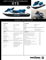
SPECIFICATIONSENGINEEngine typeInduction typeExhaust systemExhaust valve<strong>XP</strong> <strong>DI</strong>(6130/6131)Rotax 947, 2-strokeReed valveWater cooled/water injected with regulatorRotax Adjustable Variable Exhaust (RAVE)TypeOil injectionLubricationBOMBAR<strong>DI</strong>ER Formula <strong>XP</strong>-S II syntheticOil typeinjection oilNumber of cylinders 2Displacement 951.2 cm 3 (58 in 3 )Rev limiter setting7300 ± 50 RPMCOOLINGTypeELECTRICALMag<strong>net</strong>o generator outputIgnition system typeSpark plugStarting systemBatteryFuseFUEL SYSTEMFuel typeFuel injectionMake and typeGapBatteryMainCharging system(REG)VTS systemInformation center(ACC)Injection system(INJ)Fuel pump (FP)Bilge pumpOpen circuit.Direct flow from propulsion unit270 W @ 6000 RPMDigital inductiveNGK, ZFR4F1.1 mm (.043 in)Electric starter with reduction gear12 V, 19 A•h25 A30 A25 A7.5 A2 A15 A15 A3 ARegular unleaded gasoline with 87 octaneminimum (R+M)/2Orbital direct fuel injection, twin throttle body(46 mm (1.81 in))21
PROPULSIONPropulsion systemJet pump typeTransmissionReverse system<strong>XP</strong> <strong>DI</strong>(6130/6131)Bombardier Formula pumpAxial flow, single stageDirect drive/split front and rearNoJet pump oil typeSEA-DOO syntheticpolyolester oil SAE 75W90 GL5Pivoting angle of direction (nozzle) ~ 20°Minimum required water level for jet pump90 cm (3 ft)<strong>DI</strong>MENSIONSNumber of passengers ➀ 2Overall length272 cm (107 in)Overall width112 cm (44.1 in)Overall height104 cm (40.6 in)Weight274 kg (605 lb)Load limit (passengers + luggage)181 kg (400 lb)CAPACITIESFuel tank51 L (13.5 U.S. gal)Fuel tank reserve (from low level signal9.8 L (2.6 U.S. gal)Oil injection tank4 L (1.1 U.S. gal)Impeller shaft reservoirCapacityOil level100 mL (3.4 U.S. oz)Up to plug➀ Refer to load limit.BOMBAR<strong>DI</strong>ER INC. reserves the right to make changes in design and specificationsand/or to make additions to, or improvements in its products without imposingany obligation upon itself to install them on its products previously manufactured.22