NEWSfrom All Quarters of the "World - ericssonhistory.com
NEWSfrom All Quarters of the "World - ericssonhistory.com NEWSfrom All Quarters of the "World - ericssonhistory.com
Fig. 3Channel demodulator ZHP 10103/2left, completely assembledright, case and back plate removedtranslating bay (type ZDG 801), whose dimensions are as given above, isshown in fig. 2.Unit ConstructionDespite the desire to have components for universal use, units of very differentnature electrically must often unavoidably have different mechanicalcharacter. For this reason two different types of unit construction can bedistinguished in the first place:1) for units mainly with printed wiring2) for power supply and alarm equipmentUnits Mainly with Printed WiringThis type of units is illustrated in figs. 3 and 5. The electrical components inthese units are to a great extent mounted on a printed wiring card, type TV A201-209. This card has dual functions as a chassis for mechanical assemblyand as the wiring between components, in the form of connexions etched outof a layer of copper foil on one side. To connect the components to the foilFig. 4 X 8232Units occupying a single width module(less cases and back plates).Left, signalling receiver and relaycentre, channel amplifierright, channel demodulator (printed wiring side)118
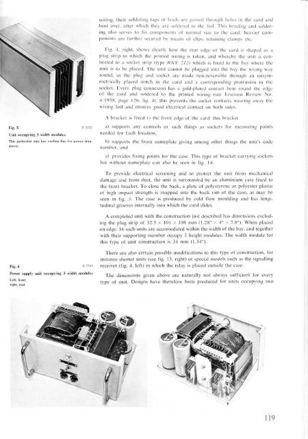
wiring, their soldering tags or leads are passed through holes in the card andbent over, after which they are soldered to the foil. This bending and solderingalso serves to fix components of normal size to the card: heavier componentsare further secured by means of clips, retaining clamps etc.Fig. 4, right, shows clearly how the rear edge of the card is shaped as aplug strip to which the printed wiring is taken, and whereby the unit is connectedto a socket strip (type RNV 212) which is fixed to the bay where theunit is to be placed. The unit cannot be plugged into the bay the wrong wayround, as the plug and socket are made non-reversible through an unsymmetrieallyplaced notch in the card and a corresponding protrusion in thesocket. Every plug connexion has a gold-plated contact bent round the edgeot the card and soldered to the printed wiring (see Ericsson Review No.4/1958, page 126, lig. 4): this prevents the socket contacts wearing away thewiring foil and ensures good electrical contact on both sides.Fig. 5 X 2527Unit occupying 3 width modulesThis particular unit has cooling fins for power tran-A bracket is fixed to the front edge of the card: this bracketa) supports any controls or such things as sockets for measuring pointsneeded for fault location,b) supports the front nameplate giving among other things the unit's codenumber, andc) provides fixing points for the case. This type of bracket carrying socketsbut without nameplate can also be seen in fig. 14.To provide electrical screening and to protect the unit from mechanicaldamage and from dust, the unit is surrounded by an aluminium case fixed tothe front bracket. To close the back, a plate of polystyrene or polyester plasticof high impact strength is snapped into the back rim of the case, as may beseen in fig. 3. The case is produced by cold flow moulding and has longitudinalgrooves internally into which the card slides.A completed unit with the construction just described has dimensions excludingthe plug strip of 32.5 X 101 X 198 mm (1.28" X 4" X 7.8"). When placedon edge, 16 such units are accomodated within the width of the bay, and togetherwith their supporting member occupy 3 height modules. The width module forthis type of unit construction is 34 mm (1.34").Fig. 6 X 7787Power supply unit occupying 3 width modulesLeft, frontright, rearThere are also certain possible modifications to this type of construction, forinstance shorter units (see fig. 13, right) or special models such as the signallingreceiver (fig. 4, left) in which the relay is placed outside the case.The dimensions given above are naturally not always sufficient for everytype of unit. Designs have therefore been produced for units occupying two119
- Page 3 and 4: ERICSSON REVIEWVol. XXXVII No. 4 19
- Page 5 and 6: application stage. To be sure, the
- Page 7 and 8: varistors and the British Post Offi
- Page 9 and 10: Gas pressure is being increasingly
- Page 11 and 12: In the field of radio link and wave
- Page 13 and 14: Fig. 4 X 7798Integrated time-multip
- Page 15 and 16: e calculated at a reasonable cost.
- Page 17 and 18: cally attractive. This means that m
- Page 19: units were either connected by plug
- Page 23 and 24: Fig. 9 X 7790Exploded drawing of th
- Page 25 and 26: Fig. 13Central part of the bayX7789
- Page 27 and 28: Fig. 17Fig. 18Fig. 17 X 8236Coaxial
- Page 29 and 30: The Centralograph Used for Producti
- Page 31 and 32: Main GroupeiCODES FOR CENTRALOGRAPH
- Page 33 and 34: in that machine's "output" column.
- Page 35 and 36: NEWS fromAll Quarters of the "World
- Page 37 and 38: LP"The Sultan of Djokjakarta operat
- Page 39 and 40: UDC 621.395(047.1)LME 82, 83, 84JAC
wiring, <strong>the</strong>ir soldering tags or leads are passed through holes in <strong>the</strong> card andbent over, after which <strong>the</strong>y are soldered to <strong>the</strong> foil. This bending and solderingalso serves to fix <strong>com</strong>ponents <strong>of</strong> normal size to <strong>the</strong> card: heavier <strong>com</strong>ponentsare fur<strong>the</strong>r secured by means <strong>of</strong> clips, retaining clamps etc.Fig. 4, right, shows clearly how <strong>the</strong> rear edge <strong>of</strong> <strong>the</strong> card is shaped as aplug strip to which <strong>the</strong> printed wiring is taken, and whereby <strong>the</strong> unit is connectedto a socket strip (type RNV 212) which is fixed to <strong>the</strong> bay where <strong>the</strong>unit is to be placed. The unit cannot be plugged into <strong>the</strong> bay <strong>the</strong> wrong wayround, as <strong>the</strong> plug and socket are made non-reversible through an unsymmetrieallyplaced notch in <strong>the</strong> card and a corresponding protrusion in <strong>the</strong>socket. Every plug connexion has a gold-plated contact bent round <strong>the</strong> edgeot <strong>the</strong> card and soldered to <strong>the</strong> printed wiring (see Ericsson Review No.4/1958, page 126, lig. 4): this prevents <strong>the</strong> socket contacts wearing away <strong>the</strong>wiring foil and ensures good electrical contact on both sides.Fig. 5 X 2527Unit occupying 3 width modulesThis particular unit has cooling fins for power tran-A bracket is fixed to <strong>the</strong> front edge <strong>of</strong> <strong>the</strong> card: this bracketa) supports any controls or such things as sockets for measuring pointsneeded for fault location,b) supports <strong>the</strong> front nameplate giving among o<strong>the</strong>r things <strong>the</strong> unit's codenumber, andc) provides fixing points for <strong>the</strong> case. This type <strong>of</strong> bracket carrying socketsbut without nameplate can also be seen in fig. 14.To provide electrical screening and to protect <strong>the</strong> unit from mechanicaldamage and from dust, <strong>the</strong> unit is surrounded by an aluminium case fixed to<strong>the</strong> front bracket. To close <strong>the</strong> back, a plate <strong>of</strong> polystyrene or polyester plastic<strong>of</strong> high impact strength is snapped into <strong>the</strong> back rim <strong>of</strong> <strong>the</strong> case, as may beseen in fig. 3. The case is produced by cold flow moulding and has longitudinalgrooves internally into which <strong>the</strong> card slides.A <strong>com</strong>pleted unit with <strong>the</strong> construction just described has dimensions excluding<strong>the</strong> plug strip <strong>of</strong> 32.5 X 101 X 198 mm (1.28" X 4" X 7.8"). When placedon edge, 16 such units are ac<strong>com</strong>odated within <strong>the</strong> width <strong>of</strong> <strong>the</strong> bay, and toge<strong>the</strong>rwith <strong>the</strong>ir supporting member occupy 3 height modules. The width module forthis type <strong>of</strong> unit construction is 34 mm (1.34").Fig. 6 X 7787Power supply unit occupying 3 width modulesLeft, frontright, rearThere are also certain possible modifications to this type <strong>of</strong> construction, forinstance shorter units (see fig. 13, right) or special models such as <strong>the</strong> signallingreceiver (fig. 4, left) in which <strong>the</strong> relay is placed outside <strong>the</strong> case.The dimensions given above are naturally not always sufficient for everytype <strong>of</strong> unit. Designs have <strong>the</strong>refore been produced for units occupying two119


