Moose Crash Test Dummy - VTI
Moose Crash Test Dummy - VTI
Moose Crash Test Dummy - VTI

You also want an ePaper? Increase the reach of your titles
YUMPU automatically turns print PDFs into web optimized ePapers that Google loves.
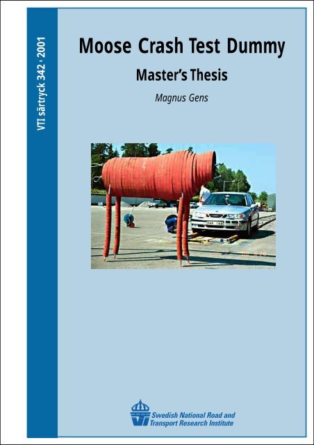
<strong>VTI</strong> särtryck 342 • 2001<strong>Moose</strong> <strong>Crash</strong> <strong>Test</strong> <strong>Dummy</strong>Master’s ThesisMagnus Gens
<strong>VTI</strong> särtryck 342 • 2001<strong>Moose</strong> <strong>Crash</strong> <strong>Test</strong> <strong>Dummy</strong>Master’s ThesisMagnus GensISSN 1102-626X
AcknowledgementsThis thesis project was initiated in 1994 and sponsored by Skyltfondenof the Swedish Road Administration. It has been performed as aMaster’s thesis project in Vehicle Engineering, at the Royal Institute ofTechnology in Stockholm, Sweden. Jan Wenäll (<strong>VTI</strong>) has beeninvolved as mentor. Professor Staffan Nordmark (<strong>VTI</strong>/KTH) served asexaminer.I thank my mentor and the rest of the people at the crash safety groupof <strong>VTI</strong> for support and company. I would also like to thank veterinaryBengt Röken with staff (Kolmården), Fredrik Burman (<strong>VTI</strong>) andTorbjörn Andersson with staff (Saab, Trollhättan) for excellentcollaboration.<strong>VTI</strong> Särtryck 342A
1. AbstractIn certain areas of our planet there are big wild animals. One bigspecies is the moose (called elk in certain regions). Scandinavia has avery large moose population and car-moose collision is a huge problemwith many fatal outcomes. In order to reduce the number of injuriescaused by passenger cars colliding with moose a valid and repeatablemethod to arrange staged accidents is needed. A moose dummy wasconstructed after thorough research work.To get well acquainted with the animal’s physical characteristics thezoo in Kolmården was visited. Veterinary Bengt Röken contributedwith expertise and general information on the moose. A recently killed– and still warm – deer was studied rigorously and that gave valuableimpressions of deer animals’ structure. The main components of the testdummy are 116 rubber plates but there are also various steel partsholding the pieces together. A database containing all part details wascreated. When the parameters were set so that the location of the centerof-gravityand shape was moose-like it was used as a platform for athree-dimensional CAD model.The idea was to keep to common materials that could be obtainedthroughout the world. Trelleborg AB in Spain manufactures the rubber.Its original purpose of use is to cover truck beds when hauling heavyrocks. The rubber quality is soft (40° Shore) and very hard to rip. Thedensity is 1050 kg/m 3 . When all the drawing work was completedprintouts were sent to the manufacturers. The dummy was assembledand crash testing began. Two modern Saabs and one old Volvo weretested. The crash test results were very pleasing since the demolishedcars looked very much like cars involved in real moose crashes. Thedummy is potent to endure many crash tests before it has to bereplaced.<strong>VTI</strong> Särtryck 342A 3
2. Contents1. Abstract ..................................................................................................................32. Contents .................................................................................................................43. Introduction............................................................................................................54. Purpose...................................................................................................................65. General Information on Accidents Involving Wild Animals.................................65.1. Miscellaneous..................................................................................................65.2. Speed...............................................................................................................75.3. Injuries of the Passengers................................................................................75.4. Damages and Deformations............................................................................85.5. Mass of the <strong>Moose</strong> ..........................................................................................95.6. The Gaskin’s Adherence to the Front Bumper ...............................................96. <strong>Moose</strong> Anatomy...................................................................................................106.1. Specifications ................................................................................................106.2. How Does a <strong>Moose</strong> React to Blunt Violence?..............................................117. Method and Material............................................................................................127.1. Literature Search ...........................................................................................127.2. Contacts.........................................................................................................127.2.1. Kolmården Zoo ......................................................................................127.2.2. Saab Automobile AB in Trollhättan ......................................................137.3. Chronology of the Construction Work..........................................................137.4. Already Existing <strong>Moose</strong> Dummies ...............................................................148. Construction of the <strong>Dummy</strong>.................................................................................158.1. <strong>Crash</strong> <strong>Test</strong> Rig...............................................................................................158.2. Material .........................................................................................................158.3. Releasing the <strong>Dummy</strong>...................................................................................168.4. Wires .............................................................................................................188.5. Shaping the Rubber Plates ............................................................................188.6. Manufacturing the Rubber Plates..................................................................208.7. Lateral Wires.................................................................................................208.8. Service Tunnel ..............................................................................................218.9. The <strong>Dummy</strong>’s Body......................................................................................218.10. The <strong>Dummy</strong>’s Legs.....................................................................................239. Results..................................................................................................................249.1. <strong>Dummy</strong>..........................................................................................................249.2. Hanging and Releasing Fundaments.............................................................2610. Verification and Validation................................................................................2711. Possibilities of Further Enhancement and Developing of the <strong>Dummy</strong>..............2912. Appendix............................................................................................................3012.1. Components ................................................................................................3012.2. Assembly.....................................................................................................3112.3. Calibration...................................................................................................3113. References..........................................................................................................324 <strong>VTI</strong> Särtryck 342A
3. IntroductionPassenger car accidents are global problems that cause many fatalities.A lot of people are struggling to decrease the amount of deaths causedby traffic and one important issue is to reduce the consequences ofcollisions. One way to reduce the number of injured people is to keepthe accident from happening. If one could be successful in accomplishingthat no in-car safety would be needed at all. But as long as thereare roads lined by forests (filled with wild animals) no assurance can begiven that there will be no obstacle on the road. Wild animals are veryunpredictable and tend to appear very suddenly. Therefore it isimportant to produce cars crash-worthy enough to give its passengersprotection for possible accidents.In Australia kangaroo accidents are common, in the Mid East and NorthAfrica there are camels and in northern Europe, northern NorthAmerica and Siberia there are moose. [2] The moose accidents are themain subject for this paper. In Sweden more than 13 moose collisionsoccur daily. That is a large number of accidents for such a smallpopulation. This has obviously made the public very aware of theimportance of driving a safe car. In order to manufacture crash-worthyvehicles extensive testing is required – maybe in combination withcomputer simulations. Computer analysis alone requires furtherdeveloping before it can provide its users with reliable data withoutvalidation through a real-life staged accident.Figure 1: Map of moose habitats.<strong>VTI</strong> Särtryck 342A 5
As a part of a crash testing concept a reliable moose dummy wasneeded. There are previous attempts that have behaved well in certainways, but lack the ability to give the vehicle the life-like deformationsthat is demanded. Therefore a new model needed to be created. Thispaper gives thorough general information on the developed dummy.4. PurposeBy supplying the car industry with an easy-to-use and easily maintainedmoose crash test dummy it may be possible to influence the safetyresearch and development teams throughout the world to focus on thistype of problems. It is intended that this dummy should be hard to missinterpretand that the user’s instructions are easy to follow. If allmanufacturers would perform tests based on the same conditions itwould provide with valuable comparison data for potential buyers. Ifthe consumers started demanding vehicles developed to protect itspassengers in this type of accident it is possible that the researchers inthis area would get larger funds. This would mean safer cars in theextension.<strong>Moose</strong> accidents are exclusive for a small percentage of the worldpopulation but there are other large wild animals in most countries. Ifno other there are riding horses and cattle that could appear on the road.That is why it should be in every manufacturer’s interest to preparetheir vehicles for this type of accident.Every moose crash is unique. That is why only extensive testing bystaging accidents can provide with reliable statistics and characteristics.Therefore it is important that the dummy itself consumes very littleresource from the test conductors. It should be easily calibrated, rigged,and maintained. The testing standard described in this report requiresthe use of a dummy built according to the description provided.5. General Information on Accidents Involving Wild Animals5.1. MiscellaneousScandinavia has a small population compared to the area it covers. Thevast forests are enriched with large numbers of deer and moose. Thesmall communities are often connected with highways without moosefences but with the speed limit 90 km/h commonly used. Thecombination of the factors mentioned above implies that travelers’safety cannot be assured by anyone. Annually 30000 car accidents6 <strong>VTI</strong> Särtryck 342A
involving cloven-footed animals in Sweden occur. [5] This meansapproximately 90 daily. Of those 90 accidents 13 involve a moose andthe majority of the rest involve roe deer. A collision with the light roedeer seldom generates injuries on the passengers although drivers areknown to veer in panic, which sometimes results in hitting a muchlarger and denser obstacle.5.2. SpeedIt is hard to detect a wild animal while travelling at high speed sincelittle time to react is given. The kinetic energy is proportional to speedraised to the second power. This makes deformations of passengercompartments significantly more severe at high speed than at lowspeed. Hence the conclusion is made that the travelling speed is of hugerelevance if one is trying to avoid to be seriously injured in a mooseaccident. Most accidents causing serious injuries occur at highwayspeeds (70-90 km/h) or above. It is also a fact that highways go throughthe areas with rich wildlife. This too makes the danger of hitting ananimal greater.Statistics indicate that the speed at which a staged moose-car accidentoccurs should be no less than 70 km/h. [4] Accidents at highway speedsare the most common (70-110 km/h), but accidents over 110 km/h arehard to evaluate due to very large deformations. Chance has muchinfluence even at low speed, and high speed gives it even moreinfluence. Furthermore most roads with the above mentioned speedlimits go through vegetated areas which often serve as moose habitat.5.3. Injuries of the PassengersThere is a very clear connection between speed and the extent of theinjuries. One study shows that the average speed in fatal accidents is90-100 km/h and for accidents causing injuries 70-80 km/h. [4] Traumato the head and throat/neck is the most common cause of death.Shattered glass cuts bare skin easily. Crumbled steel interferes with thehead’s path. Light and medium light cars are dominating the statisticsof vehicles involved in accidents that resulted in injuries. The seat beltis apparently not of much use in a moose crash due to the modestdecrease in velocity.<strong>VTI</strong> Särtryck 342A 7
5.4. Damages and DeformationsA common scenario is when the moose legs are being swept awayresulting in the animal rotating over the engine hood. The bonnet isdeformed when the moose lands on it. Fractions of a second later thebody hits the windshield beam and the front pillars (A-posts). Theanimal crushes the windshield when crashing into it with itsmomentum. The windshield alone is not strong enough to deflect theheavy animal. The A-posts are generally dimensioned for higher loadsthan the perpetual windshield beam. [6] The welds that connect the A-posts to the perpetual play a significant role in the course – if they failto endure the stress the moose body will end up in the front seat (oreven back seat). The permanent deformation is often very substantial.The laminated glass used in modern car’s windshields is fairly strong; itconsists of two glass sheets that are connected by a plastic film. Butpieces of glass sling loose as an effect to powerful blows and theshattered glass has momentum enough to seriously damage the face andeyes of the passengers. These wounds are commonly seen. The sidewindows tend to break as well.The retardation causes various body parts to move, which can bedangerous when sharp and naked metal is in the trajectory. Byrecalculating the minimal requirements of the beams that frame thewindshield it is possible that the number of seriously injured in thistype of accident could be significantly reduced. Most passenger carscould probably need reinforcing in these sections.The retardation of the vehicle when hitting a moose – from a generalpoint of view – is not extreme. [7] A typical accident may include a1000-kg car and a 300-kg moose. Let us assume that the car travelswith a speed of 90 km/h. The law of linear momentum yields:Vafter=Vmbeforecar⋅ m+ mcarmoose∆v≈ 70 − 90 = −20km / h90 ⋅1000=1300≈ 70 km / hThis is not a ∆v known to seriously injure or kill passengers due toextreme retardation. It is deformed metal, shattered glass, and themoose itself that jeopardizes the passengers’ lives. At the impact thepassengers’ heads sling forward. If the roof crumbles in at the sametime it might interfere with the head’s trajectory. Deformations can give8 <strong>VTI</strong> Särtryck 342A
the passengers very little space left possibly causing cuts and bluntblows to the upper parts of the body.The hooves are very tough while the bones are fragile. This results inthe bones breaking instantly leaving muscles, strings and ligaments tomaintain the shape of the moose. In the initial phase of an accident themoose’s legs adhere to the front bumper. This gives the upper body arotating momentum causing the moose to spin almost 90 degrees beforehitting the windshield fundament.5.5. Mass of the <strong>Moose</strong>The moose involved in accidents are mostly young light animals. InMay one-year-olds are diverging from their mothers causing them tobehave confused. Young bulls cover large areas in the mating season,which occurs in autumn. Large animals are more seldom involved inaccidents but are obviously causing huge damages when impact occurs.It would not be suitable to design a dummy that features the mostfavorable characteristics possible. The dummy needs to be relativelyheavy. It is obviously not – in general – the light animals that cause themost serious accidents. It has been a great challenge to construct adummy that is adequately tough on the tested cars. Preferably adangerous, near lethal, scenario should be created.5.6. The Gaskin’s Adherence to the Front BumperWhen hit by most passenger cars the center-of-gravity of the moosepasses over the engine bonnet thus avoiding the energy absorbing partslocated in the car’s front end. Hence follows that the legs alone take thefirst blow. The bones are instantly broken leaving the remains of thelegs to behave as ropes. The hoof is basically a tough lump connectedto the bottom end of this “rope”. For a fraction of a second the gaskinwill fold around the bumper causing the leg to adhere to the car for avery short lapse of time. The shoulder and pelvis establishes leversfrom the joints to the center of gravity. When the legs are exposed to apulling force this will cause the body to rotate.<strong>VTI</strong> Särtryck 342A 9
Initially the body is rotated exclusively. Earlier studies show that thecenter-of-gravity barely is displaced until at a later stage of theaccident. [1] The moose is not accelerated in the travelling directionuntil it is hit by the windshield fundament hence the car is exposed torelatively small force at the initial stage.6. <strong>Moose</strong> Anatomy6.1. SpecificationsFigure 2: The rotation of the moose.A Swedish moose can weigh up to 600 kg but the average mass of ananimal involved in an accident is around 200 kg. When the calf is oneyear old the mother rejects it. This occurs in May, which is the timewhen accidents happen most frequently. The first couple of weeks thecalf acts very confused and wanders about randomly. [3] By that timethe calf can weigh up to 200 kg. Due to more generous supply of foodin the summer the moose are generally significantly heavier in autumnthan spring.According to Röken the center of gravity of a full-grown moose isfound approximately 1350 mm above the ground inside the seventh rib.The withers are 1700-2000 mm (and the loin is situated 1600-1900mm) above the ground. The legs contribute with approximately 10% ofthe total mass, the neck with 5% and the head with 3%. The front legscarry 58% of the weight while the rear couple holds up 42%.10 <strong>VTI</strong> Särtryck 342A
LoinWithersGaskinFigure 3: <strong>Moose</strong> measures.<strong>Moose</strong> may give a sturdy impression but in fact the body is quiteslender. A big moose bull is no broader than 500 mm. The chestincreases in depth (vertical) with the weight though. The legs are longbut very thin. Thighs, shoulders, and loins are dense. The chest,abdomen, and flank are soft and give way.6.2. How Does a <strong>Moose</strong> React to Blunt Violence?When a moose is exposed to powerful blunt violence one will besurprised by how jointless it appears. The body seems to lack innerstructure. [1] Furthermore one can notice that the shoulders and thepelvis are not rotating in phase. Hence the dummy’s ends should havethe same ability to rotate independently.Bones put under crash-stress are crushed instantly. It is the strings,muscles, and hide that hold the body parts together. Note that theoutside measures differ very little throughout the impact. The abdomenwith its contents has a very dynamic course though.<strong>VTI</strong> Särtryck 342A 11
<strong>Moose</strong> are very flexible. If the A-posts accelerate the rear and front endof the moose’s body the center section will still put plenty of stress onthe windshield and the roof. The windshield often yields to the pressureand collapses. This phenomenon is very dangerous due to thepossibility of the moose ending up in the passenger’s lap. The moose’sweight is one danger another is when it is trying to come loose, hencekicking its legs about. <strong>Moose</strong> remain surprisingly undamaged on theoutside. The hide is very tough.7. Method and Material7.1. Literature SearchThere are books describing moose and its behavior. There are alsobooks describing how human bodies respond to blunt violence andretardation. There are no books combining the two subjects though. Inthe United States studies have been performed on corpses by exposingthem to violence. Some papers on earlier dummies were also found.A master’s thesis describes the staging of a moose accident [1] and theconstruction of a simple dummy. An ill and weak moose bull was put todeath and quickly afterwards it was hit by a Volvo 240 at a speed of 79km/h. The authors also produced a film taken by high-speed camerasfrom several different angles. Their paper is written to be educativefrom a future dummy constructor’s point-of-view.In Metoder för att minska viltolyckor [4] one can read about a similarliterature search. They have also come to conclusion that not manypublications are to find.7.2. Contacts7.2.1. Kolmården ZooThe moose as a species is hard to generalize. The mass of the animaldiffers significantly and so do the outside measures. The food supplyand the time-of-year make the moose vary from slim to bulky. To getinformation on the moose veterinary Bengt Röken of Kolmårdens zoowas contacted. The zoo has approximately ten moose in an enclosedpasture. Two three-year-old bulls had been bottle fed since birth andwere tame. These two were studied and photographed rigorously fromshort distance. Hours have been spent with the moose in this enclosure.12 <strong>VTI</strong> Särtryck 342A
As a veterinary, hunter, and moose enthusiast Bengt possesses greatknowledge on the animal’s physical structure. Data on the center-ofgravityhas been a key subject. Bengt has also studied the 1:5 scaledmodel that was built. The latter resulted in a couple of minor changes ofthe design.7.2.2. Saab Automobile AB in TrollhättanAt an early stage of the project two Swedish car manufacturers werecontacted. Both were asked if they would be interested in taking part inthis moose project. It was important to get the car industry involved inorder to get access to their experience and information on their needs. Itwas also important to get hold of crash-test cars. The project proceededin a very successful collaboration with Saab in Trollhättan.The crash safety division at Saab was visited twice. They havecontributed with information from their accident database andexpertise. The crash test experts criticized the scaled model in aconstructive way providing with their aspects as actual potential users.They also decided to supply two Saab 9-5 for crash testing purposes.7.3. Chronology of the Construction WorkA literature search initiated the project. Reading the master’s thesiswritten at CTH in 1984 [1] was worthwhile.The dummy rigging equipment was developed to cast a minimalamount of shade over the dummy and car. All colors should be dark,dull and discrete except for the dummy and car – which should bebrightly colored. The dummy should be upgradable and re-shapeablee.g. if the model was to be converted into a different type of animal orif insufficiencies was to be discovered. When the adequate informationhad been obtained the collaboration with Saab and Kolmården wasinitiated.<strong>VTI</strong> Särtryck 342A 13
Computer models were created to visualize the body shape andcalculate the center-of-gravity. When the results were acceptable thescale 1:5 model was manufactured. The local workshop of <strong>VTI</strong> cut theplates out of rubber and sheet metal. The experts were consulted onceagain for advice and this led to some minor modifications. The finalversion was ordered in full scale.All the parts were assembled on the assembly rig. Calibratingspecifications were created. (See the appendix.) Several test releaseswere performed in order to make sure that the mechanism workedproperly and to decide on an optimal tightening level for the spinewires.Three tests were conducted to verify the dummy and compare it withearlier tests and data. <strong>Test</strong>s at 70 and 90 km/h were performed.7.4. Already Existing <strong>Moose</strong> DummiesIn earlier projects two dummies have been developed. One variantconsists of water filled rubber hoses, another of electrical wires inbundles with a wooden beam for spine. Both of these dummies lack thesimulation of legs hence losing the rotation in the initial phase of anaccident.Characteristics of the wire moose:• Poor reproducibility• Difficult to calibrate• Very compact and rigid• Low production cost• The wooden beam simulates the spine poorly• The absence of legs•Characteristics of the hose moose:• Complicated to repair• Easily manufactured• Well defined damages• The absence of legs• Potential water leak14 <strong>VTI</strong> Särtryck 342A
8. Construction of the <strong>Dummy</strong>8.1. <strong>Crash</strong> <strong>Test</strong> RigIt is very important to let the vertical rigging wires loose exactly (orslightly in advance of) when the car hits the dummy. If the dummy isconnected to the releasing frame at the time of impact the body will notbe able to rotate as freely as expected. The rotation causes the body tohit the passenger compartment with the back first. Instead of theshoulder, thigh, and belly first.It is of significance to be able to get good quality high-speed films ofthe course of events. Therefore it is important to keep the releasingframe as slender as possible. Furthermore it should be spacious enoughto enable crash tests with vans and small trucks. The rig should bemoveable after having been fully assembled.8.2. MaterialA material for the making of the plates used in the dummy should betough, tear-proof, and have the correct softness. The material has to besoft. Earlier studies imply that their dummies have been too densecausing it to generate non-realistic deformations. The rubber used willhave to put up with shattered glass, sharp edges, and tremendous loadsbut still it has to be long lasting.The rubber market has been thoroughly examined and a satisfyingquality has been found. The chosen rubber is called RF 19 Red and ismanufactured by Trelleborg Industri AB. Identical rubber can beordered and delivered internationally. This is a soft (and very durable)rubber quality and is originally used for protecting truck beds whenhauling heavy and sharp rocks. The density is 1050 kg/ m 3 and thesoftness is Shore 40°. A moose has a total density of approximately1000 kg/ m 3 . The dummy consists of rubber and steel so to adjust to theproper density various cavities has been carved in the rubber body. Byplacing these holes cleverly the body can obtain very life-like weightand compressibility. Certain body parts of the moose are compact whileothers are soft.<strong>VTI</strong> Särtryck 342A 15
To make the rubber-to-rubber friction well defined all rubber surfaceswere treated with magnesium powder. This powder’s original purposeis to be used on the palms of weightlifters. It makes the hands dry andnon-slippery. It has been bought from Casall AB in Norrköping. Thedummy-to-car friction is large but compared to the force in a highspeedaccident it is insignificant.Certex Svenska AB has especially manufactured the wires that simulatethe spine. The slip-on protective rubber hose is cut from ordinarygarden hose. All sheet metal details are cut out of 5-mm steel sheets.The dummy will be hanging from ten pieces of 3-mm steel wire. This ismore than enough to bear the full load.8.3. Releasing the <strong>Dummy</strong>The performance of the crash-test rig is of huge significance. Stagedcollisions are expensive and require rigorous preparations. This is whythe mechanism (which lets the moose loose) must never surprise itsusers. The trigging time and the complete release of the dummy are twoimportant issues. There are several different methods with which suchmechanism can be constructed.The following concept were thought of as applicable:Pyrotechnically:If steel wires are used to hang the dummy it can be released by cuttingthe wires. Ten wires are needed to keep the dummy’s contour authentic.The wires can be cut pyrotechnically with small, safe, and reliabledevices. Many wires mean many cutters thus making each releaseexpensive.Gliding:The rubber plates could be slipped onto a rigid steel bar, leaving somedistance sticking out at each end. The bare steel is placed on lowfrictionsupports. When the dummy is hit by the test car it is supposedto slide off from the stand in the pre-phase of the staged accident. Thisrigging method will be worthless if the leg-contact would show not tobe enough to get the dummy loose, which would keep the moosedummy from rotating properly before impacting with the passengercompartment.16 <strong>VTI</strong> Särtryck 342A
Cradle:Instead of hanging the dummy it can be held upright by a carefullycarved block made out of a light material. This block has to turn over ina very predictable way but it also has to be stable enough not to flipshortly before the crash moment. The linear momentum of the blockhas to be negligible thus it has to be light. [7] Possible materials arefoam plastics due to their low specific mass and low-cost shaping. Aproblem is the appearance; one will have to consider whether this setuplooks authentic enough. Some foam plastics are also known to burstinto particles possibly causing the area to look blizzard struck.Sheet cradle:Support from under can arrange the dummy in a realistic and life-likeway. Wrapping a cloth around the dummy and hang it from thereleasing frame can do this. Possible problems are difficulties to releasein a satisfactory fashion and the sheet tends to block camera views.Mechanical cutting of wires:The test car runs over a lever connected to a wire cutter. The rubbermoose is hanging in the same fashion as described in Pyrotechnically.The set-up is calibrated by adjusting the distance between the lever anddummy.Electromagnetic locking:A steel pipe connected to the frame via ball bearings is equipped withsmall steel rods sticking out from the side. The dummy will cause thepipe to rotate due to the leverage developed when the moose is hungfrom these rods. This is why two electrical magnets fasten the pipe. Ongiven command the current to the magnets is cut and the moose fallsdown. This rig is calibrated by adjusting the distance from the switch tothe rig. This is the method incorporated in this concept.There is a problem with a transcendental magnetic field, which coulddelay the releasing procedure. The advantage of adjustable triggingequipment makes this a problem easily dealt with though. A high-speedcamera will be used to evaluate the delay in the releasing procedure. Achart of trigging distances related to testing speeds was plotted. Seechart 1.<strong>VTI</strong> Särtryck 342A 17
Figure 4: Releasing mechanism with electrical magnets.8.4. WiresThe dummy will be hung from the top spine wire. Each of the verticalwires has a steel ring connected to each end. They all have the exactsame length. The rods intended to hang the moose from are only 10 mmlong; this is to keep the steel rings from jamming when the dummy fallsdown.8.5. Shaping the Rubber PlatesFrom moose sketches by Bengt Röken and pictures the shape of thedummy was formed. The smooth contour then had to be adjusted, to bewell described by 36 rubber plates. A database consisting of 36 plates,and various data on them, was created. The two most importantvariables are the height of the plate and the offset of the top wire holefrom the plate center. Adjustment of each individual plate finally gavesatisfactory results height-wise. The width of the dummy is constantover the body with the exceptions of the plate in the very back and theseven front plates. <strong>Moose</strong> are surprisingly slim and non-varying inwidth.18 <strong>VTI</strong> Särtryck 342A
Figure 5: Sketch of rubber plate (cross-section).Each plate has the shape of an ellipse. It is possible that a drop shapedcross-section could describe the body even better, but this is plainspeculation. The dummy is intended to be a simplified model of a reallifemoose. Main characteristics have been given priority causing manydetails to go out of focus. With a model simplified correctly one canhopefully conduct crash tests without getting unpleasant surprises.Another issue of huge importance is that chance must not interferewhen testing passenger cars.With the legs disregarded a moose has its vertical center-of-gravityapproximately in the center of the body. The moose’s specificationsvary significantly due to the food supply and time-of-year. The body isdense and compact with exception of the belly, which is easy to deformyet heavy. To create a rubber plate that fulfills these specificationshollow sections are distributed over the sheet. The top half has cavitiesfocused to the center while the lower section has cavities in the outerregions. (See figure 5) This causes the lower part of the dummy to beinitially soft, while the top part appears more solid. Still the center-ofgravityremains approximately in the center.<strong>VTI</strong> Särtryck 342A 19
This dummy is regarded as competent to demolish a passenger car in anauthentic fashion, yet it is easy to use and requires a minimum amountof repair. It can handle large series of crash tests with only short breaksfor calibration and cleaning.Each sheet of rubber has been visualized by using three-dimensionalcomputer software. The plates and other mounting parts was virtuallyassembled and rendered pictures gave hints of the final result. Thisprocedure showed to be a valuable tool in the designing process. Whenthe result was pleasing a scale 1:5 model was created. Bengt Röken andthe crash-safety staff at Saab evaluated the small dummy and someminor changes were performed.8.6. Manufacturing the Rubber PlatesA drawing was printed for each plate. It only had to show one view dueto the simplicity of the design. The paper size had to be A1 in order tofit the largest parts. The pen width used was 0.5 mm. These drawingswere delivered to a company in Göteborg. The people at this companyare experts at cutting complicated patterns in rubber sheets. They use avery highly pressurized water beam to slice the material. The cuttingmachine is controlled by an optical reader, which scans the drawingsand cuts the rubber simultaneously. The rubber was delivered in theshape of two seven-m 2 sheets. The slicing method mentioned above didnot warp the edges, which a steel blade would have done. All together36 large body plates and 80 leg discs were cut out.8.7. Lateral WiresThe two lateral spine wires (which keeps the rubber plates in position)were initially meant to carefully track a real-life moose’s back column.But later it became obvious that some height between the upper andlower wire was required. This makes the dummy adequately stiff in thevertical direction and also keeps the individual plate non-indifferent torotating forces. The spine consists of two 10-mm steel wires. Each wireis equipped with a threaded bolt in one end. On the outer end of thethread a wrench seat has been machined. See figure 10. The other endremains non-coated to keep its ability to slip through the wire holes inthe plates.The vertical distance between the steel ropes cannot be to great due tobody shape limitations. The plates in the very front and rear are not atlevel. It is important that the dummy in fact resemble a moose.20 <strong>VTI</strong> Särtryck 342A
Furthermore a tunnel was to be fitted between the spine wires. Finallythe distance of 190 mm was decided on (center-to-center). The spinewires also hold the pelvis, shoulders, and end plates in place. Whenfully inserted the wires are fastened with four competent rope grips.The tightening of the nuts with the torque given in Calibrationcompletes the installation.8.8. Service TunnelFigure 6: Rear plate and looped spine wires.Between the upper and the lower rope there is a tunnel. This tunnel’smain tasks are to evenly distribute the mass over each rubber sheet andto provide the possibility to assemble the dummy on a rod. The tunnelhas the diameter of 110 mm. The layer of rubber surrounding the topwire is thicker than the layer that surrounds the bottom wire. This is dueto idea that the top rope should transfer forces in all directions while thelower rope mostly should limit individual plate’s tendencies to rotate.8.9. The <strong>Dummy</strong>’s BodyThe dummy body consists of 36 rubber plates. They are all 50 mmthick but the area varies. The idea for this construction is based on thefact that the other plates will retain sudden movements of an individualplate. This will create a non-bouncing close-to-solid body.Two horizontally running wires keep the discs together. There is a steelplate mounted at each end to transfer the wire forces into the rubber.When hanging from the releasing frame the rubber plates will beslightly pressed together.<strong>VTI</strong> Särtryck 342A 21
Soft construction materials tend to deform while under stress. Duringthe impact a rubber body will stretch, which a moose will not. Theshape of a moose remains surprisingly intact. Even though the bonesbreak the body will be held together by ligaments, muscles, and strings– and not to forget the hide. It is therefore important that the spine wirescan cope with the stress that the impact produces and retain the lengthexpansion. The tensile strength has to be great but the flexibility is veryimportant as well. The large animals are very bendable and non-rigid.This ability is maintained in the dummy with this two-wire concept.A calculation sheet yielded the total mass, center-of-gravity coordinates,and the required area of sheet rubber. A chart based on thecalculation data shows a side view projection of the dummy. Thiswould prove to be very helpful.8006004002000-200-400-600-800-1000-500 0 500 1000 1500 2000 2500upper contour lower contour wire1 (upper)wire1 (lower) wire2 (upper) wire2 (lower)center-of-gravitycenter-of-gravity (horiz.)Figure 7: The side view visualization of the dummy.When the parameter set gave satisfactory results they were inserted intoa three-dimensional CAD program. Each rubber part was individuallysketched and then virtually assembled to give a visualization of thedummy at an early stage of the project.22 <strong>VTI</strong> Särtryck 342A
Figure 8: Virtually assembled dummy.Having the above mentioned 3D visualization finalized a scaled downmodel was created. Bengt Röken and various Saab people evaluatedthis scale one-to-five model. After this evaluation the drawings wereslightly modified – the dummy was redesigned to be a little bit shorter.No fundamental or conceptual changes were performed.8.10. The <strong>Dummy</strong>’s LegsInitially the intention was to simulate the legs with one to three steelwires or chains. A lump of something tough was to be attached to theend – simulating the moose feet. The hooves are tough, wide and,strong. Rubber hoses were to be slipped on the leg wires but thisconcept would not be life like. The mass on a moose leg is evenlydistributed. The above-mentioned construction would be nonappropriate.The mass of a real leg is approximately 8 kg, which isimpossible to reach by using only flexible and slim wires. So insteadfour thin wires lined with rubber discs were incorporated. This conceptgives the dummy legs good characteristics.<strong>VTI</strong> Särtryck 342A 23
The legs consist of rubber discs and steel ropes. They start out from thesteel plates that simulate the pelvis and shoulders. The force vector isoffset from the center-of-gravity causing the body to rotate if the legsare exposed to vertical force. See figure 11. Sketches in the thesis paperfrom Nilson and Svensson [1] show the position of the moosethroughout an impact. These sketches clearly indicate that the moose’scenter-of-gravity barely moves during the initial stage of the accident.The force the moose is exposed to only causes the animal to rotate. Thepelvis, shoulders, and belly all rotate with different angular velocity.9. Results9.1. <strong>Dummy</strong>The horizontal center of gravity is located in the 18:th disc from therear. This is a good result considering that the head is disregarded inthis dummy. The head is very dynamic during an impact. Whendetermining if the head will cause major destruction chance plays a bigrole. For example the head is potent to easily break a side windowspreading shattered glass in the passenger compartment. But it is verydifficult (if not impossible) to predict such damage. Especially whenconsidering that cars vary in width, height, and so on. The long neckwill cause the head to start slinging way after the body’s center ofgravity first is displaced. A real-life moose has its center-of-gravityaround the 7:th rib. This causes the real moose to have slightly moreweight on the front legs than the dummy.Name Pcs Mass SumLeg wire 8 0,5 4Rear plate 1 3 3Front plate 1 2,9 2,9Shoulder/pelvis 2 2,75 5,5Rubber plates 1 307,5 307,5Spine wire with hose 2 2 4nuts, wires, rope grip 2 0,5 1Leg disc 78 0,25 19,5Leg disc fastener 4 0,1 0,4Total mass:348Table 1: Mass in kilograms.The sheet rubber revealed a thickness of only 48-mm. This factadjusted the total mass to 330 kg.24 <strong>VTI</strong> Särtryck 342A
The vertical center of gravity on a moose is placed approximately 1350mm above ground. The dummy’s center-of-gravity will depend on theleg length, which after consultation of Bengt Röken was decided toextend 1000 mm under the chest. This leg length gives comparablecenter-of-gravity’s. Once again it is emphasized that every moose isunique. <strong>Moose</strong> are hard to generalize.Figure 9: Tightening nuts.Figure 10: Overview of pelvis, spine wires, and leg system.The rubber parts were kept from sliding off by screw-locked aluminumwashers initially. This locking device had four wire holes, each onewith a locking M5 screw. After having introduced the dummy to a testcar this locking device proved itself too weak. At the present the legrubber is retained by washers and press-on steel tube.<strong>VTI</strong> Särtryck 342A 25
The leg origin from the pelvis and shoulder structures. Each legconsists of four five-millimeter wires. These are mounted according tofigure 11 and are interlocked at the bottom end of the dummy’sshinbone. 19 rubber discs cover each front leg, while the rear legs eachhave 20 discs.Figure 11: <strong>Dummy</strong> hanging from the releasing frame.9.2. Hanging and Releasing FundamentsWhile waiting on being hit the dummy hangs from the releasing frame.Under the top beam there is a pipe connected with ball bearings. Thepipe is free to rotate around its own axle. 15 small perpendicular rodsare welded to this pipe in a line with 100 mm between them. See figure4 and 11. When hung on these rods the dummy creates torque aroundthe pipe’s axle due to force offset. A counter momentum is created withtwo electrical magnets and when their circuit is broken the dummy willfall down. The circuit is broken fractions of a second before impact thusthe body is effected by no forces at the time of collision. The dummy isreleased after approximately 65 ms when the circuit is broken.26 <strong>VTI</strong> Särtryck 342A
2,75trigging distance ahead of collision [m]2,52,2521,751,51,2510,750,50,25020 40 60 80 100 120 140test speed [km/h]Chart 1: Chart of distance related to speed.During the preparations two M4 screws lock the pipe. These screwsshould be securely fastened until all preparations have been completedand everything is ready for impact.10. Verification and ValidationSaab Automobile AB in Trollhättan contributed with two Saab 9-5passenger cars. These cars were tested in 70 respectively 90 km/h. Ahigh-speed shutting camera filmed the impacts enabling thoroughevaluation to be conducted.Figure 12: Two test cars.<strong>VTI</strong> Särtryck 342A 27
The press-on bolts on the spine wires were bent when the dummytumbled on the ground. Supports for these bolts need to be welded tothe front steel plate. When the dummy is hit at greater speed than 70km/h the rear and front plate are starting to warp. These need to bereinforced, which easily can be done. Furthermore the leg disc retainerneeds updating.<strong>Test</strong> 1:A Volvo 245 were driven into the dummy at 72 km/h. A few leg discswas peeled off each leg due to too small hoof washers. The cardeformations were very pleasing and the dummy behaved well. Highspeedcameras produced films that showed a very life-like dummytrajectory. Pictures in Viltolyckor [8] show the same deformations.<strong>Test</strong> 2:A Saab 9-5 was driven into the dummy at 72 km/h. The reinforced legretainer kept all leg discs threaded on the leg wires. Once again the testcar was damaged in a very pleasing way. The result resembled a lot of areal-life accident that had been investigated by Saab engineers.<strong>Test</strong> 3:The second Saab was tested at 92 km/h, which appears to be the upperlimit for both passenger cars and dummies. Some damages appeared onthe rubber moose after this test. The decrease in speed during theimpact was 15 km/h. The retardation reached a peak value of 10 g.Figure 13: <strong>Dummy</strong> crashed Volvo.Figure 14: Authentically crashed Volvo.28 <strong>VTI</strong> Särtryck 342A
11. Possibilities of Further Enhancement and Developing of the<strong>Dummy</strong><strong>VTI</strong> has already been asked to design a camel and horse dummy.Serious or not this inquiry indicates that there is a worldwide interest inthis type of testing. In Australia tests with kangaroo dummies havealready been conducted. These are also hard to generalize due to a verydynamic center-of-gravity, which vary very much in vertical position.This dummy concept is easily transformed to various animals. TheCAD model only needs re-shaping. Help from a veterinary or expert onthe animal is preferable in order to get the correct characteristics in thedummy. It is important to study the animal thoroughly before makingthe simplified model that this concept will yield. Compromises couldremove characteristic properties (and make the dummy worthless) if notproperly conducted.This concept is very well prepared for simulations using finite elementmethods. FEM is a very wide spread way to evaluate car crashworthinessthese days and can be very cost effective compared to realstaged accidents. This dummy can be converted into FEM software. Itis possible that already existing 3D-models can be imported into someprograms.The head could be incorporated in a dummy concept. This would makethe dummy even more appealing. The head and neck would form apendulum. The pendulum’s resonance frequencies and so on need to bethoroughly evaluated.<strong>VTI</strong> Särtryck 342A 29
12. Appendix12.1. ComponentsHorizontal wires:2 Pcs 2.5-m, 10-mm steel wire with threaded bolt pressed ontoone end.2 Pcs 2-m rubber hose (12-mm inner diameter and 19-mm outerdiameter).4 Pcs Wire grip.Shoulder complex with front legs:1 Pcs Shoulder plate (according to drawing).4 Pcs 2.8-m, 5-mm steel wires.38 Pcs Rubber discs (according to drawing).2 Pcs Press-on tube with washer.Pelvis complex with rear legs:1 Pcs Pelvis plate (according to drawing).4 Pcs 2.8-m, 5-mm steel wire.40 Pcs Rubber discs (according to drawing).2 Pcs Press-on tube with washer.Body:36 Pcs Rubber plates (according to drawings).1 Pcs Front plate (according to drawing).1 Pcs Rear plate (according to drawing).Assembly frame:1 Pcs Hanging fundament (according to drawing).<strong>Crash</strong> test frame:1 Pcs Hanging fundament with releasing mechanism (accordingto drawing).30 <strong>VTI</strong> Särtryck 342A
12.2. AssemblyHanging wires are to be mounted between plate 2-3, 6-7, 10-11, 14-15,18-19, 22-23, 26-27, 28-29, 30-31 and 34-35.The pelvis should be mounted between plate 3 and 4. The shouldersshould be mounted between 27 and 28.A non-petroleum lubricant should be used when threading the bodyplates on the spine wires.12.3. CalibrationAll rubber surfaces are powdered with magnesium carbonate. A roughnon-treated surface has a very high friction coefficient, which willmake the dummy behave as a solid piece of rubber. A bouncing effecteasily comes to mind.The releasing trigger needs to be set at an adequate distance ahead ofimpact. (See chart 1.) The upper spine wire should be tightened withthe torque of 4 Nm. The lower rope with 2 Nm. The center of the testcar should be in line with the boundary between plate 15 and 16. (Theplates are numbered from behind)<strong>VTI</strong> Särtryck 342A 31
13. References1. G. Nilson and M. Svensson, ”Fullskalesimulering av bilälgkollisionmedälgkadaver”, Chalmers TekniskaHögskola, Göteborg, 19862. Diverse jägare och naturmänniskor, ”Ett hundra frågor omälgen”, Skogsstyrelsen, Jönköping, 19933. B. Almkvist, ”Älgens ålder och kön”, Zoologiskainstitutionen, Stockholms universitet, Stockholm, 19794. M. Lindquist and Ronnie Lundström, “Metoder för attminska viltolyckor – En översikt”, Vägverket, Region Norr,19975. J. Ifver, “Trafikolyckor på det statliga vägnätet 1992”,Vägverket – Miljö & Trafiksäkerhet, Borlänge, 19936. Various, “Bil-Älgkollisioner”, Hedemora Bilteknik, 19847. T. Turbell, “Simulerade älgkollisioner – en metodstudie”,<strong>VTI</strong>, Linköping, 19848. B. Lind, “Viltolyckor”, Volvo (Informationsavdelningen),198032 <strong>VTI</strong> Särtryck 342A