Neopuff Infant Resuscitator Technical Manual - utenti
Neopuff Infant Resuscitator Technical Manual - utenti
Neopuff Infant Resuscitator Technical Manual - utenti

You also want an ePaper? Increase the reach of your titles
YUMPU automatically turns print PDFs into web optimized ePapers that Google loves.
<strong>Neopuff</strong> TM <strong>Infant</strong> <strong>Resuscitator</strong> <strong>Technical</strong><br />
<strong>Manual</strong><br />
This is a <strong>Technical</strong> <strong>Manual</strong> only, for instructions on how<br />
to operate the <strong>Neopuff</strong> TM <strong>Infant</strong> <strong>Resuscitator</strong> please refer<br />
to the Operating <strong>Manual</strong>.<br />
Maximum Pressure<br />
Relief Cover<br />
Inlet Port<br />
HInternational: 15 Maurice Paykel Place, PO Box 14-348, Panmure, Auckland, New Zealand.<br />
Tel: 64 9-574-0100 Fax: +64-9-574-0158 www.fphcare.com<br />
Australia: 36-40 New Street, Ringwood, Victoria 3134, Australia. Tel: +61-3-9879-5022 Fax:<br />
+61-3-9879-5232<br />
UK and Ireland: Unit 16 Cordwallis Park, Clivemont Road, Maidenhead, SL6 7BU, United<br />
Kingdom. Tel: +44-1494-464-333 Fax: +44-1494-464-888 *European Union Authorized<br />
Representative<br />
France: Parc Silic-Bal F, 10 Avenue de Quebec, Silic S12 Villebon, 91946, Courtaboeuf<br />
Cedex, France. Tel: +33-1-6446-5201 Fax: +33-1-6446-5221<br />
Germany: Hundsberger Str 45, 73642 Welzheim, Germany Tel: +49-7182-937 770 Fax: +49-<br />
7182-937 7799<br />
USA: Suite 101 22982 Alcalde Drive, Laguna Hills, California 92653, USA Tel: +1- 714 -470-<br />
3900 Fax: +1 - 714-470-3933 Toll Free: +1-800-446-3908<br />
Ref 185041597 Rev B Jun 03<br />
End Cap<br />
Manometer<br />
Peak Inspiratory<br />
Pressure Control<br />
Outlet Port<br />
End Cap
1.0 Performance Characteristics and<br />
Specifications<br />
1.1 Caution<br />
• Input gas flow rate 5-15 LPM, recommended operating gas flow rate 8 LPM. Do not attempt<br />
to use a higher flow than 15 LPM.<br />
• Factory setting of pressure relief valve is at 40cm H2O. This setting is user adjustable up to<br />
80cm H2O. Do not attempt to set the pressure relief valve above 80-cm H2O. Reset<br />
pressure relief valve to 40cm H2O after use (refer 4.2.3 of this manual).<br />
• Use only recommended Fisher & Paykel Healthcare <strong>Neopuff</strong> TM <strong>Infant</strong> <strong>Resuscitator</strong><br />
accessories.<br />
• Do not use substances that are incompatible with O2.<br />
1.2 Typical Performance<br />
Inspiratory pressure range<br />
@ 5 LPM approx. 2-73cm H2O [mbar]<br />
@ 8 LPM approx. 4-73 cm H2O [mbar]<br />
@ 10 LPM: approx. 5-75 cm H2O [mbar]<br />
@ 15 LPM approx. 10-77cm H2O [mbar]<br />
Input gas flow range:<br />
Minimum 5 LPM<br />
Maximum 15 LPM<br />
Peep range at:<br />
5 LPM 1-5 cm H2O [mbar]<br />
8 LPM approx. 1-9 cm H2O [mbar]<br />
10 LPM 2-15 cm H2O [mbar]<br />
15 LPM 4-25 cm H2O [mbar]<br />
If the gas flow rate increases from 5 to 15 LPM, peak pressure values will increase by<br />
approximately 8 cm H2O [mbar].<br />
Operating time (400 litre cylinder):<br />
5 LPM 80 minutes<br />
10 LPM 40 minutes<br />
15 LPM 26 minutes<br />
PLEASE NOTE: The above figures are typical only.<br />
1.3 <strong>Technical</strong> Specifications<br />
Manometer range: -20 to 80cm H2O [mbar]<br />
Manometer accuracy: +/-2.0% of FSD<br />
Maximum pressure setting: 65-80 cm H2O [mbar]<br />
(dependant on flowrate)<br />
Dimensions:<br />
Height 250mm (9.8”)<br />
Width 200mm (7.9”)<br />
Depth 100mm (3.9”)<br />
Weight 2.1kg (4.6lb)<br />
Operating and storage 0 0 C to 50 0 C, up to 90% humidity<br />
Recommended body weight: 0-10kg (22lb)<br />
Delivered oxygen concentration: Up to 100%
4.2.3 Setting Maximum Pressure Relief to 40cm H2O<br />
This is required if the maximum pressure relief has been changed. The factory setting for<br />
he maximum pressure setting is 40cmH2O. This should be adjusted in accordance with<br />
hospital protocol.<br />
1. Adjust gas flow to 10 LPM.<br />
2. Turn the peak inspiratory pressure knob fully clockwise<br />
3. Adjust the maximum pressure relief valve clockwise or counter-clockwise until the<br />
manometer reads 40cm H2O.<br />
4. Turn the peak inspiratory pressure knob anticlockwise so the manometer reads 20cm<br />
H2O and shut off the gas flow.<br />
4.2.4 Manometer Replacement<br />
The manometer is not a serviceable item and must be replaced by Manometer Kit<br />
043040841.<br />
1. Remove back cover, fixed by four screws<br />
2. Disconnect tube from manometer.<br />
3. Remove manometer by unscrewing the two retaining nuts<br />
4. Fit the new manometer into front panel, tighten retaining nuts and re-connect manometer tube.<br />
5. Record date code found on back of replacement manometer and serial number of<br />
<strong>Neopuff</strong> infant resuscitator from back cover and send copy to Fisher & Paykel<br />
Healthcare, Attention Neonatal Regulatory Affairs.<br />
6. Re-fit front panel to back cover with four screws.<br />
7. Complete Testing of Manometer (4.2.2)<br />
4.2.5 Valve Replacement<br />
Note: the valves are an integral part of the valve, fascia and manifold assembly and are not<br />
able to be serviced. Please specify model number from parts list (3.2.1) when ordering a<br />
replacement valve assembly.<br />
1. Remove back cover, fixed by four screws<br />
2. Remove plugs and remove end caps by unscrewing four cap screws per end.<br />
3. Disconnect tube from manometer.<br />
4. Remove manometer by unscrewing the two retaining nuts<br />
5. Record valve assembly and <strong>Neopuff</strong> TM <strong>Infant</strong> <strong>Resuscitator</strong> serial numbers and send<br />
copy to Fisher & Paykel Healthcare, Attention Neonatal Regulatory Affairs.<br />
6. Fit existing manometer into new valve assembly panel, tighten retaining nuts and reconnect<br />
manometer tube.<br />
7. Re-fit front panel to back cover with four screws.<br />
8. Re-fit ends caps with four cap screws per end and replace plugs.<br />
9. Complete Testing of Manometer (4.2.2)<br />
2.0 Cleaning of the RD900 <strong>Neopuff</strong> TM <strong>Infant</strong><br />
<strong>Resuscitator</strong><br />
2.1 Cleaning<br />
Clean the external surfaces of the <strong>Neopuff</strong> TM <strong>Infant</strong> <strong>Resuscitator</strong> either weekly or between<br />
patients using a damp cloth with dilute mineral acids, an acid-salt solution or correctly diluted<br />
disinfectant-detergent solution. Ensure that the manufacturer’s directions for use of the<br />
cleaning agent are followed. Dry all surfaces after cleaning with a clean soft cloth or paper<br />
towel<br />
2.2 Test Lung<br />
If required the test lung can be sterilized using ethylene oxide gas only. Please note that the<br />
test lung is constructed of latex and is susceptible to attack by solvents. Ensure no solvents<br />
are used to clean the test lung.<br />
2.3 WARNING<br />
• Latex construction of the test lung may cause irritation.<br />
2.4 CAUTIONS<br />
• DO NOT use any compounds containing aromatic hydrocarbons, ammonia, aqueous<br />
solutions or abrasive products. Use of alcohol based solutions may cause plastic<br />
surfaces to craze and crack.<br />
• Ensure all oxygen and air supplies are turned off and disconnected from the <strong>Neopuff</strong> TM<br />
<strong>Infant</strong> <strong>Resuscitator</strong> before performing cleaning procedures. Explosion and fire hazards<br />
can exist when performing cleaning procedures in an oxygen-enriched environment.<br />
• Before cleaning, remove and discard all used single use products using the recommended<br />
method of disposal.<br />
• Do not attempt to clean single use products.<br />
• The above methods of cleaning are suitable for the components, but the suitability of any<br />
method for a particular bacteriological situation is the responsibility of the user.<br />
• Do not autoclave or gas sterilise the <strong>Neopuff</strong> TM <strong>Infant</strong> <strong>Resuscitator</strong>.<br />
• Ensure all parts and accessories are checked before returning the device to service<br />
• For ethylene oxide gases: Some carrier gases can cause stress cracking and are not<br />
suitable. If in doubt check with chemical supplier.<br />
• Do not reuse single use <strong>Neopuff</strong> TM <strong>Infant</strong> <strong>Resuscitator</strong> products
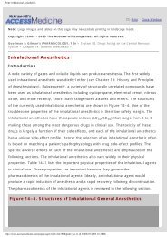
3.0 Assembly Diagram<br />
3.1 Serial Numbers before 99R9xxx083<br />
For serial numbers predating 99R9___083, the diagram below represents the internal<br />
components of the <strong>Neopuff</strong> TM <strong>Infant</strong> <strong>Resuscitator</strong>.<br />
Maximum Pressure<br />
Relief Cover<br />
Inlet Port<br />
4.2.2 Testing of Manometer<br />
End Cap<br />
Manometer<br />
Peak Inspiratory<br />
Pressure Control<br />
Outlet Port<br />
End Cap<br />
The manometer can be tested against a calibrated gauge using the following guidelines. The<br />
inlet port must be connected with a flow generator capable of generating constant flow at 5<br />
and 10 LPM. The outlet port must be connected with a bleed valve and the certified gauge<br />
being used.<br />
1. Lift the cover off the maximum pressure relief valve slightly and rotate out of the way.<br />
2. Completely close the maximum pressure relief valve by turning fully clockwise.<br />
3. At 10LPM the manometer should be within +/−2cm H2O of the certified gauge at 10, 20 and<br />
40cm H2O<br />
4. The manometer should have risen/fallen smoothly between the settings by using the<br />
peak inspiratory pressure control when the bleed valve is activated.<br />
5. At 5 LPM set the manometer to 70cm H2O, the certified gauge should read a minimum of<br />
65cm H2O.<br />
6. At 10 LPM the unit should not generate pressures greater than 83cm H2O.<br />
7. Turning the maximum pressure relief valve counter-clockwise reset the maximum<br />
pressure to 40cm H2O. (4.2.3)<br />
8. Replace the maximum pressure valve cover by rotating the cover back into place and<br />
pressing it onto the valve stem.<br />
9. Once testing is completed reset the peak inspiratory pressure to 20cm H2O and turn off<br />
gas flow.<br />
If the manometer fails on any of these settings then it should be regarded as inaccurate<br />
and replaced immediately with a replacement manometer 043040841. Follow<br />
manometer replacement guidelines in section 4.2.4 of this manual.
4.0 Service Information<br />
4.1 Functional schematic<br />
4.2 Preventative Maintenance<br />
• The <strong>Neopuff</strong> TM <strong>Infant</strong> <strong>Resuscitator</strong> should receive annual servicing or maintenance<br />
when used under normal conditions. This should include Testing of the Manometer<br />
(4.2.2), Setting the Maximum Pressure Relief to 40cm H2O (4.2.3) and if required<br />
Resetting the Manometer to Zero (4.2.1), Manometer Replacement (4.2.4) and Valve<br />
Replacement (4.2.5) of this manual.<br />
• Both of the adjustment knobs should rotate easily without play, failure to do this may<br />
indicate damage to the valves and Valve Replacement (4.2.5) should be carried out.<br />
• The integrity of the system and manometer should be checked annually and after<br />
servicing using include Testing of the Manometer (4.2.2).<br />
• Qualified personnel using only Fisher & Paykel Healthcare parts must carry out all<br />
maintenance.<br />
• Always ensure gas passages are free from contaminants, especially hydrocarbons,<br />
prior to re-assembly.<br />
• Ensure only approved replacement parts are used during service and maintenance<br />
procedures.<br />
• Please contact an authorised Fisher & Paykel Healthcare representative for further<br />
assistance with any servicing or maintenance requirements.<br />
• The test lung should be replaced within three years of purchase.<br />
4.2.1 Resetting the Manometer to Zero<br />
To zero the manometer:<br />
10. Disconnect <strong>Neopuff</strong> <strong>Infant</strong> <strong>Resuscitator</strong> from any other equipment.<br />
11. Remove opaque plastic plug in lens of manometer<br />
12. Using suitable slot screwdriver adjust clockwise (+) or counter-clockwise (-) to reset<br />
manometer to zero<br />
13. Replace plastic plug in lens of manometer<br />
14. Complete Testing of the Manometer (4.2.2)<br />
3.1.1 Parts List<br />
# Description Part Number Reqd<br />
1 Screw #8x1” CSK HD. 616050011 4<br />
2 Screw #8x1” Pan HD. 614040153 2<br />
3 Manifold block. Includes plug, T-piece, tube and 2 screws.See note<br />
4 Reservoir. Includes 2 bungs, fitting and tube. See note<br />
5 End cap 693040741 2<br />
6 Screw M8x20. 614040309<br />
7 Plug set of 5. 693040706 1<br />
8 Foot. 693041436 4<br />
9 Plastic panel See note<br />
10 Cover, max pressure relief, permanent and removable. 043041057<br />
11 Connector 10mm female gas inlet. 500RD509<br />
12 Model specific front fascia, please specify exact model 1<br />
English 233201448 Dutch 233201518<br />
German 233201467 Swedish 233201521<br />
Italian 233201468 Portuguese 233201522<br />
Spanish 233201469 Danish 233201523<br />
French 233201470 Finnish 233201524<br />
Japanese 233201471 Norwegian 233201525<br />
13 Connector 10mm male gas outlet. 500RD508 1<br />
14 Manometer kit 043040841 1<br />
15 Cap, inspiratory pressure valve. 043042345 1<br />
16 Valve assemblies, pair. See note<br />
17 Column. 641040816 1<br />
18 Screw M4x8 Pan HD. 614040117 2<br />
19 Handle 641040809 1<br />
Service kit, includes C-spanner and adapter for torque driver. 500RD521<br />
Note – Parts 3,4,9 and 16 are no longer available due to model update to that shown in 3.2.<br />
To replace any of these parts please order from the following language specific panel, fascia<br />
and valve assembly spare part:<br />
Model specific panel and valve assembly (kit includes fascia)<br />
English 043042347 Dutch 043042353<br />
German 043042348 Swedish 043042354<br />
Italian 043042349 Portuguese 043042355<br />
Spanish 043042350 Danish 233201523<br />
French 043042351 Finnish 233201524<br />
Japanese 043042352
3.2 Serial numbers after 99Rxxx083<br />
On 29/03/01 serial numbers changed from the above format to the EAN format. The first<br />
number in the sequence was 010329000001. There was no change to the model itself.<br />
3.2.1 Parts List<br />
# Description Part Number Reqd<br />
1 Handle 641040809 1<br />
2 Plug (set of four) 693040706 2<br />
3 Screw M8x20 614040309 8<br />
4 End cap 693040741 2<br />
5 Back cover 641040816 1<br />
6 Model specific panel and valve assembly (kit includes fascia) 1<br />
English 043042347<br />
German 043042348<br />
Italian 043042349<br />
Spanish 043042350<br />
French 043042351<br />
Japanese 043042352<br />
Dutch 043042353<br />
Swedish 043042354<br />
Portuguese 043042355<br />
Danish 233201523<br />
Finnish 233201524<br />
7 Manometer kit 043040841 1<br />
8 Model specific front fascia, please specify exact model 1<br />
English 233201448<br />
German 233201467<br />
Italian 233201468<br />
Spanish 233201469<br />
French 233201470<br />
Japanese 233201471<br />
Dutch 233201518<br />
Swedish 233201521<br />
Portuguese 233201522<br />
Danish 233201523<br />
Finnish 233201524<br />
Norwegian 233201525<br />
9 Cap, inspiratory pressure valve 043042345 2<br />
10 Cover, maximum pressure relief 043041057 1<br />
11 Foot 693041436 4<br />
12 screw #8x1” Csk hd 616050011 4<br />
--- Screw M4x8 Pan hd (not shown, handle attachment) 614040117 2<br />
--- Test lung (not shown) 042040542 1