You also want an ePaper? Increase the reach of your titles
YUMPU automatically turns print PDFs into web optimized ePapers that Google loves.
LIFT CORP.11921 Slauson Ave.Santa Fe Springs, CA. 90670CUSTOMER SERVICE:TELEPHONE (562) 464-0099 TOLL FREE (800) 227-4116FAX: (888) 771-7713NOTE: For latest version of all Manuals (and replacements), download theManuals from <strong>Maxon</strong>’s website at www.maxonlift.com.WARRANTY/ RMA POLICY & PROCEDURELIFTGATE WARRANTYType of Warranty:Term of Warranty:Full Parts and LaborStandard Liftgates - 2 years from ship date or 6,000 cyclesPremium Liftgates - 2 years from ship date or 10,000 cyclesThis warranty shall not apply unless the product is installed, operated and maintained in accordance with MAXON Lift’s specifications as set forthin MAXON Lift’s Installation, Operation and Maintenance manuals. This warranty does not cover normal wear, maintenance or adjustments,damage or malfunction caused by improper handling, installation, abuse, misuse, negligence, or carelessness of operation. In addition, thiswarranty does not cover equipment that has had unauthorized modifications or alterations made to the product.MAXON agrees to replace any components which are found to be defective during the first 2 years of service, and will reimburse for labor basedon MAXON’s Liftgate Warranty Flat Rate Schedule. (Copy of the Flat Rate is available at www.maxonlift.com.)All warranty repairs must be performed by an authorized MAXON warranty facility. For any repairs that may exceed $500, including parts andlabor, MAXON’s Technical Service Department must be notified and an “Authorization Number” obtained.All claims for warranty must be received within 30 Days of the repair date, and include the following information:1. Liftgate Model Number and Serial Number2. The End User must be referenced on the claim3. Detailed Description of Problem4. Corrective Action Taken, and Date of Repair5. Parts used for Repair, Including MAXON Part Number(s)6. MAXON R.M.A. # and/or Authorization # if applicable (see below)7. Person contacted at MAXON if applicable8. Claim must show detailed information I.e. Labor rate and hours of work performedWarranty claims can also be placed on-line at www.maxonlift.com. On-line claims will be given priority processing.All claims for warranty will be denied if paperwork has not been received or claim submitted via <strong>Maxon</strong> website for processing by MAXON’sWarranty Department within 30 days of repair date.All components may be subject to return for inspection, prior to the claim being processed. MAXON products may not be returned without priorwritten approval from MAXON’s Technical Service Department. Returns must be accompanied by a copy of the original invoice or reference withoriginal invoice number and are subject to a credit deduction to cover handling charges and any necessary reconditioning costs. Unauthorizedreturns will be refused and will become the responsibility of the returnee.Any goods being returned to MAXON Lift must be pre-approved for return, and have the R.M.A. number written on the outside of the package inplain view, and returned freight prepaid. All returns are subject to a 15% handling charge if not accompanied by a detailed packing list. Returnedparts are subject to no credit and returned back to the customer.Defective Parts requested for return must be returned within 30 days of the claim date for consideration to:MAXON Lift Corp.16205 Distribution Way, Cerritos, CA 90703Attn: RMA#__MAXON’s warranty policy does not include the reimbursement for travel time, towing, vehicle rental, service calls, oil, batteries or loss of incomedue to downtime. Fabrication or use of non <strong>Maxon</strong> parts, which are available from MAXON, are also not covered.MAXON’s Flat Rate Labor Schedule takes into consideration the time required for diagnosis of a problem.All Liftgates returned are subject to inspection and a 15% restocking fee. Any returned Liftgates or components that have been installed or notreturned in new condition will be subject to an additional reworking charge which will be based upon the labor and material cost required to returnthe Liftgate or component to new condition.PURCHASE PART WARRANTYTerm of Warranty: 1 Year from Date of Purchase.Type of Warranty: Part replacement onlyMAXON will guarantee all returned genuine MAXON replacement parts upon receipt and inspection of parts and original invoice.All warranty replacements parts will be sent out via ground freight. If a Rush Shipment is requested all freight charges will be billed to therequesting party.
Comply with the following WARNINGS while maintaining Liftgates. See Operation ManualM-04-05 for operating safety requirements.!WARNINGS• Read and understand the instructions in this Maintenance Manual before performing maintenanceon the Liftgate.• Before operating the Liftgate, read and understand the operating instructions in Operation ManualM-04-05.• Comply with all WARNING and instruction decals attached to the Liftgate.• Keep decals clean and legible. If decals are defaced or missing, replace them. Free replacementdecals are available from <strong>Maxon</strong> Parts Department.• Consider the safety and location of bystanders and location of nearby objects when operating theLiftgate. Stand to one side of the platform while operating the Liftgate• Do not allow untrained persons to operate the Liftgate.• Do not stand under, or allow obstructions under the platform when lowering the Liftgate. Be sureyour feet are clear of the Liftgate.• Keep fingers, hands, arms, legs, and feet clear of moving Liftgate parts (and platformedges) when operating the Liftgate.• Correctly stow platform when not in use. Extended platforms could create a hazard forpeople and vehicles passing by.• Disconnect Liftgate power cable from battery before repairing or servicing Liftgate.• Wear apppropriate safety equipment such as protective eyeglasses, faceshield and clothing whileperforming maintenance on the Liftgate and handling the battery. Debris from drilling and contactwith battery acid may injure unprotected eyes and skin.• Be careful working by an automotive type battery. Make sure the work area is well ventilated andthere are no flames or sparks near the battery. Never lay objects on the battery that can short theterminals together. If battery acid gets in your eyes, immediately seek first aid. If acid gets on yourskin, immediately wash it off with soap and water.• If an emergency situation arises (vehicle or Liftgate) while operating the Liftgate, release the controlToggle Switch and the Liftgate will stop.• A correctly installed Liftgate operates smoothly and reasonably quiet. The only noticeable noiseduring operation comes from the pump unit while the platform is raised. Listen for scraping, gratingand binding noises and correct the problem before continuing to operate Liftgate.• If it is necessary to stand on the platform while maintaining the Liftgate, keep your feet and anyobjects clear of the inboard edge of the platform. Your feet or objects on the platform could betrapped between the platform and the Liftgate extension plate.11921 Slauson Ave. Santa Fe Springs, CA. 90670 (800) 227-4116 FAX (888) 771-7713• Never perform unauthorized modifications on the Liftgate. Modifications may result in early failure ofthe Liftgate and may create hazards for Liftgate operators and maintainers.• Use only <strong>Maxon</strong> Authorized Parts for replacement parts. Provide Liftgate model and serialnumber information with your parts order. Order replacement parts from:MAXON LIFT CORP. Customer Service11921 Slauson Ave., Santa Fe Springs, CA 90670Phone: (800) 227-4116• To order parts by e-mail, submit orders to partssales@maxonlift.com.5
LIFTGATE TERMINOLOGYEXTENSIONPLATE11921 Slauson Ave. Santa Fe Springs, CA. 90670 (800) 227-4116 FAX (888) 771-7713PLATFORMLIFTCYLINDERPARALLELARMCONTROLSWITCHPLATFORMOPENERFLIPOVER WITHFIXED RAMPLIFTARMMAINFRAMEPUMPBOXSAFETYHOOK6
THIS PAGE INTENTIONALLY LEFT BLANK11921 Slauson Ave. Santa Fe Springs, CA. 90670 (800) 227-4116 FAX (888) 771-77137
PERIODIC MAINTENANCEPERIODIC MAINTENANCE CHECKLIST!WARNINGNever operate the Liftgate with parts loose or missing.NOTE: Make sure Vehicle is parked on level ground while performing themaintenance checks.11921 Slauson Ave. Santa Fe Springs, CA. 90670 (800) 227-4116 FAX (888) 771-7713Annually or 5000 Cycles (whichever occurs first)Visually check the entire Liftgate for excessively wornparts and broken welds, especially Hinge Pins. SeePARTS BREAKDOWN section for replacement parts.Check the Platform and Flipover as follows. WithPlatform open at Bed Height (Vehicle Body),check the outboard edge of Flipover. The outboardedge must be just above level line asshown in FIG. 8-1. If outboard edge of Flipoveris below the level line, check pins and bearingsat the pivot points on both sides of the Liftgate(see FIG. 8-2). See PARTS BREAKDOWNsection for replacement parts.LIFTCYLINDERLIFT ARMPARALLELARMPLATFORMTo prevent unnecessary wear onParallel Arms, check for worn flangedbearings as follows. Position the Platform1”-2” above ground (FIG. 9-1A).Push against the Shackle (FIG. 9-1B,item 1) and measure clearance (FIG.9-1B, item 1). Then push against otherside of Shackle (FIG. 9-1B, item 2)and measure clearance (FIG. 9-1B,item 2). Repeat for LH side Shackle. Ifclearance is less than 0.060”, replaceflanged bearing. See PARTS BREAK-DOWN section for replacement parts.8OUTBOARDEDGELEVEL LINEPLATFORM EDGE ABOVEBED LEVELFIG. 8-1PIVOT POINTS(PINS & BEARINGS)PIVOT POINTS TO CHECKFIG. 8-2Also, do the Semi-annual or 2500 Cycles and Quarterly or 1250 Cycles checks.
ISO 15 HYDRAULIC OILRECOMMENDED BRANDSAMSOILAWF-05TABLE 11-2ISO-10 OR MIL-H-5606 HYDRAULIC FLUIDRECOMMENDED BRANDSPART NUMBERCHEVRONFLUID A, AW-MV-1 5KENDALLGLACIAL BLUSHELLTELLUS T-1 5EXXONUNIVIS HVI-1 3MOBILISO 32 HYDRAULIC OILRECOMMENDED BRANDSAMSOILAWH-05CHEVRONHIPERSYN 32KENDALLTABLE 11-1DTE-11 MPART NUMBERGOLDEN MVSHELLTELLUS T-3 2EXXONUNIVIS N-32MOBILDTE-24,DTE-13M,HYDRAULIC OIL-13PART NUMBER11921 Slauson Ave. Santa Fe Springs, CA. 90670 (800) 227-4116 FAX (888) 771-7713AMSOILCHEVRONKENDALLN/ AFLUID A, FLUIDGLACIAL BLUGSHELLAEROSHELL FLUID-4 1EXXONUNIVIS HVI-1 3MOBILAERO HFATABLE 11-311
PERIODIC MAINTENANCECHANGING HYDRAULIC FLUIDCAUTIONKeep dirt, water and other contaminants from entering the hydraulic system.Before opening the hydraulic fluid reservoir filler cap, drain plug and hydrauliclines, clean up contaminants that can get in the openings. Also, protect the openingsfrom accidental contamination.11921 Slauson Ave. Santa Fe Springs, CA. 90670 (800) 227-4116 FAX (888) 771-7713NOTE: Use correct grade of hydraulic fluid for your location.+70 to +140 Degrees F - Grade ISO 32+40 to +105 Degrees F - Grade ISO 15Below + 70 Degrees F - Grade ISO 10 or MIL-H-5606See TABLES 9-1, 9-2 & 9-3 on previous page for recommended brands.GRAVITY DOWN LIFTGATES1. Remove the Pump Cover (FIG. 12-2). Place empty5 Gallon Bucket under Drain Plug (FIG. 12-1).2. Lower Platform to ground. Pull out (no threads)Drain Plug (FIG. 12-1). Drain hydraulic fluidfrom system. Reinstall Drain Plug.3. Pull out (no threads) Filler Cap (FIG. 12-1) andrefill reservoir with Hydraulic Fluid to level shown inFIG. 12-1. Reinstall Filler Cap (FIG. 12-1).CAUTIONPump Cover must be correctlysecured to prevent it from becominga hazard. To secure PumpCover, the long side of the HolderFlats must be installed as shownin the illustration.NUTS4. Bolt on the Pump Cover as shown in FIG. 12-2.Torque the 5/16”-18 cover bolts Torque the5/16”-18 cover bolts 20 to 29 LBS.-FT.DRAIN PLUGGRAVITY DOWN PUMP & MOTORFIG. 12-1FLATWASHERSFILLERCAPPOWER UNIT(REF)RESERVOIR5-1/2”PUMP COVERLONG SIDE OFHOLDER FLATSPUMP COVER CAPSCREWSUNBOLTING / BOLTING PUMP COVERFIG. 12-212
POWER DOWN LIFTGATES1. Remove the Pump Cover (FIG. 10-2). Place empty5 Gallon Bucket under Drain Plug (FIG. 10-1).2. Open and raise Platform to vehicle bed height.Pull out (no threads) Drain Plug (FIG. 10-1).Drain hydraulic fluid.3. Disconnect the Motor Power Cable (FIG. 13-1)from bottom Starter Solenoid. Lower the Platformwhile draining the remaining hydraulic fluid fromsystem. Reinstall Drain Plug. Reconnect theMotor Power Cable to bottom Starter Solenoid.Torque hex nut to 95 LBS.-IN.4. Pull out (no threads) Filler Cap (FIG. 10-1) andrefill reservoir with Hydraulic Fluid to level shownin FIG. 10-1. Reinstall Filler Cap (FIG. 10-1).CAUTIONPump Cover must be correctlysecured to prevent it from becominga hazard. To secure PumpCover, the long side of the HolderFlats must be installed as shownin the illustration.5. Bolt on the Pump Cover as shown in FIG. 13-2.Torque the 5/16”-18 cover bolts Torque the 5/16”-18 cover bolts 20 to 29 LBS.-FT.BOTTOMSTARTERSOLENOIDHEX NUTMOTOR POWERCABLEPOWER DOWN PUMPFIG. 13-111921 Slauson Ave. Santa Fe Springs, CA. 90670 (800) 227-4116 FAX (888) 771-771313
PERIODIC MAINTENANCEREPLACING PLATFORM TORSION SPRINGNOTE: The following procedure shows how to replace Torsion Spring on RH side ofPlatform. Use this procedure for replacing Torsion Spring on the LH Side.11921 Slauson Ave. Santa Fe Springs, CA. 90670 (800) 227-4116 FAX (888) 771-77131. Fold Flipover onto Platform.2. Fold Platform.3. Raise Liftgate to a convenient work heightto gain access and release tension on theTorsion Spring.!CAUTIONTo prevent injury and equipment damage,make sure there is no tension on torsionspring before removing hinge pin.4. Unbolt Hinge Pin from Shackle and SpringBracket (FIG. 14-1). Remove bolts, washers,and lock nuts. Drive the Hinge Pin outboardtoward the Shackle just enough to free thetorsion spring (FIG. 14-2). Remove theTorsion Spring.5. Install the Torsion Spring as shown in FIG.14-3. Make sure the long leg of the spring isinserted in the Spring Bracket (FIG. 14-3).Make sure the short end of the spring isvisible and resting against the Hinge Bracket(FIG. 14-3).6. Drive the Hinge Pin into correct positionthrough the Hinge Bracket as shown inFIG. 14-3. Line up the bolt hole in theHinge Pin with the hole in the Shackleand Spring Bracket. Bolt the Hinge Pin toHinge Bracket and Spring Bracket withbolts, washers, lock nuts (FIG. 14-2).Torque the 3/8”-16 Spring Pin bolt and3/8”-16 Spring Bracket bolt 35 to 52LBS.-FT.7. Operate the Liftgate according toinstructions in Operation Manualto make sure it operates correctly.SPRINGBRACKETWASHERWASHERBOLTSPRINGBRACKETLONGLEGBOLTTORSIONSPRINGLOCK NUTHINGEBRACKETWASHERSHACKLELOCK NUTFIG. 14-1FIG. 14-2SHORTCHAMFEREDLEGWASHERSHACKLEFIG. 14-3HINGEPINHINGEBRACKETSHACKLEBOLTBOLT14
PARTS BREAKDOWN11921 Slauson Ave. Santa Fe Springs, CA. 90670 (800) 227-4116 FAX (888) 771-771315
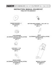
GPT MAIN ASSEMBLY1A1REFER TO PUMPCOVER, HYDRAULICCOMPONENTS, &POWER UNITS11921 Slauson Ave. Santa Fe Springs, CA. 90670 (800) 227-4116 FAX (888) 771-77131BREFER TO MAIN FRAME, LIFT-ING ARMS & PARALLEL ARMSREFER TO PLATFORM &FLIPOVER ASSEMBLYI TEM Q TY.PARTNO.1 1DESCRIPTION281090-01EXTENSION PLATE ASSEMBLY, 96" LG.281090-02EXTENSION PLATE ASSEMBLY, 102" LG.1A6 207644RIVE T1B1 050175MAXON PLATE2 4 902000-14FLAT WASHER, 1/2"3 2 900035-3CAP SCREW 1/2"-13 X 1-1/2" L.G.4 2 901010LOCK NUT, 1/2"-135 1280998-01UNDERRIDE, 96"280998-02UNDERRIDE, 102"5A2 908008-01BEARING46 2 902013-21FLAT WASHER, 1-3/8"7225A63537289625A47 2 221416ROLL PIN8 1 226938EYE, DROP FORGED PAD 3/4" X 1-1/2"9 1 227700HOOK ASSEMBLY16
THIS PAGE INTENTIONALLY LEFT BLANK11921 Slauson Ave. Santa Fe Springs, CA. 90670 (800) 227-4116 FAX (888) 771-771317
MAIN FRAME, LIFTING ARMS, & PARALLEL ARMSGPT 25 & GPT-33I TEM Q TY.PARTNO.DESCRIPTION1 1280910-01MAINFRAME, 96" WIDE280910-02MAINFRAME, 102" WIDE2 2 040103-5SPLIT LOOM3 8 205780PLASTIC TIE S4 2 280969-02PIN, 1-3/8" DIA X 6" LG.5 2 280968-01PIN, 1-3/8" DIA X 5-7/8" LG.6 2 281005-01PIN, 7" LG.7 12221416ROLL PIN8 2 280912-01PARALLEL ARMS8A8 908037BEARING8B2 908024-01BEARING9 2 902013-21FLAT WASHER, 1-3/8"101 280915-01LIFT ARM, RH10A1 908023-01BEARING10B1 908023-02BEARING111 280915-02LIFT ARM, LH11A1 908023-01BEARING11B1 908023-02BEARING122 281127-01PIN, CYLINDE R132 908012-01CAM FOLLOWER142 030334LOCK NUT, 5/8"-18152 280918-01OPENER15A2 280082-01ROLLER15C2 902000-14FLAT WASHER, 1/2"15D2 901010LOCK NUT, 1/2"-13176 902000-10FLAT WASHER, 3/8"181 281000-02BRACKET, LH194 901002LOCK NUT, 3/8"-16202 900014-11CAP SCREW, 3/8"-16 X 3" LG.212 281004PIN, SPRING11921 Slauson Ave. Santa Fe Springs, CA. 90670 (800) 227-4116 FAX (888) 771-771315B2 900035-8CAP SCREW, 1/2"-13 X 2-3/4" LG.162 900014-9CAP SCREW, 3/8"-16 X 2-1/4" LG.221 280971-02SHACKLE, LH232 280976-01PIN, 5-5/8" LG.241 280950-02TORSION SPRING, LH251 281000-01BRACKET, RH261 280950-01TORSION SPRING, RH271 280971-01SHACKLE, RH282 281102-01SADDLE294 900035-7CAP SCREW 1/2"-13 X 2-1/2" LG.308 902000-16FLAT WASHER, 9/16"314 901010LOCK NUT, 1/2"-1319
PLATFORM & FLIPOVER ASSEMBLYREFER TOPLATFORMASSEMBLY11921 Slauson Ave. Santa Fe Springs, CA. 90670 (800) 227-4116 FAX (888) 771-77131B1C415I TEM Q TY.PARTNO.1 11A125232DESCRIPTION280999-01FLIPOVER ASSEMBLY, 79-1/2" LG.280999-02FLIPOVER ASSEMBLY, 85-1/2" LG.280995-01FLIPOVER WELDMENT, 79" LG.280995-02FLIPOVER WELDMENT, 85" LG.1B2 280941-01SIDE PLATE, FLIPOVE R1C10900705-01SELF-TAPPING SCREW, 1/4"-20 X 1" LG.1A2 15281010-01HINGE ASSEMBLY1B1C (10 PLACES)5543 2 263456-13HINGE, ROD4 4 905015-1ROLL PIN5 4 902000-14FLAT WASHER, 1/2"20
PLATFORM ASSEMBLY1312516I TEM Q TY.PARTNO.REF11 1738DESCRIPTION281000-01PLATFORM ASSEMBLY, 79-1/2" LG.281000-02PLATFORM ASSEMBLY, 85-1/2" LG.280992-01PLATFORM WELDMENT, 79" LG.280992-02PLATFORM WELDMENT, 85" LG.2 1 281070-01SUPPORT, RH3 6 902013-11FLAT WASHER, 3/8"4 6 901002LOCK NUT, 3/8"-16439105112313 (10 PLACES)8934310711921 Slauson Ave. Santa Fe Springs, CA. 90670 (800) 227-4116 FAX (888) 771-77135 6 900064-07BUTTONHEAD SCREW, 3/8"-16 X 3" LG.6 1 281070-02SUPPORT, LH7 2 908026-01BEARING, 1-3/4" LG.8 2 908008-02BEARING, 5/8" LG.9 6 902011-6LOCK WASHER, 1/2"106 900035-5CAP SCREW, 1/2"-13 X 2" LG.111 280987-01SIDE PLATE, RH, PLATFORM121 280987-02SIDE PLATE, LH, PLATFORM1310900705-01SELF-TAPPING SCREW, 1/4"-20 X 1" LG.21
11921 Slauson Ave. Santa Fe Springs, CA. 90670 (800) 227-4116 FAX (888) 771-7713THIS PAGE INTENTIONALLY LEFT BLANK22
PUMP COVER & MOUNTING PLATE ASSEMBLYMAIN FRAME(REF)67589486510 11312121312 VDC POWER UNIT(REF)I TEM Q TY.PARTNO.1 1 281038-01COVER ASSYDESCRIPTION2 1 093203-10GASKET, RUBBER CHANNEL, 60" LG.3 2 90009-8CAP SCREW, 5/16"-18 X 2" LG.4 2 281062-02HOLDER FLATS5 2 902013-10FLAT WASHER, 5/16"6 2 901001LOCK NUT, 5/16"-1814NOTE: LEAVE 1/4” GAP FOR DRAINAGE.7 1 900064-03BUTTONHEAD SCREW, 3/8"-16 X 3/4" LG.432111921 Slauson Ave. Santa Fe Springs, CA. 90670 (800) 227-4116 FAX (888) 771-77138 2 902011-4LOCK WASHER, 3/8"9 1 900064-04BUTTONHEAD SCREW, 3/8"-16 X 7/8" LG.101 903400-02LOCK WASHER, EXTERNAL TOOTH112 266428-02GROMMET, 1/4"HOLE122 908022-01PLUG, FLEXIBLE134 908022-03PLUG, FLEXIBLE141 281065-01PLATE, PUMP MOUNT23
GRAVITY DOWN HYDRAULIC COMPONENTSRH CYLINDER10SEE 12 VDC POWER UNIT(GRAVITY DOWN)LH CYLINDER1A1A1 1B1B6141172139215 1718 1811921 Slauson Ave. Santa Fe Springs, CA. 90670 (800) 227-4116 FAX (888) 771-77131A34516PUMPMOUNTINGPLATE (REF)17I TEM Q TY.PARTNO.121 2 280990-01CYLINDER (GPT-25/33 )1A2 908033POLYLUBE BEARINGDESCRIPTION1B2 280990SK-01SEAL KIT (GPT-25/33 CYLINDER )2 2 906704-01ELBOW, 90° F/S, #8 M-M3 1 281057-01HOSE ASSY, 3/8" HP, 40" LG.4 2 228012ADAPTER, STRAIGHT THREAD, 9/16"-18 M - 1/4" F5 2 202406ELBOW, BRASS 1/4" x 1/4"6 1 224370-21HOSE, PLASTIC 38" LG.7 1 224370-18HOSE, PLASTIC 95" LG.8 1 281057-02HOSE ASSY, 3/8" HP, 112" LG.9 1 224370-20HOSE, PLASTIC 9" LG.101 906749-01UNION TEE17CAUTIONTo prevent incorrect operation & damage to liftgate, make surearrow on flow regulator valve points up as shown in illustration.111 281067-01F/S TUBE ASSY121 906744-01BULKHEAD UNIO N133 902028-12FLAT WASHER, 3/4"141 906708-01ELBOW, 90° F/S, #6 M-M151 906709-03FLOW REGULATOR VALVE, 3GPM111975481A161 906745-01BRANCH TEE175 906712-02O-RING, #6 (3/8" FACE SEAL TUBE-END )182 906712-03O-RING, #8 (1/2" FACE SEAL TUBE-END )191 906728-01DUAL BARBED FITTIN G24
12 VDC POWER UNIT (GRAVITY DOWN)12CONTROL SWITCHWIRING HARNESS(REF)I TEM Q TY.PARTNO.47DESCRIPTIONREF281015-0112 VDC POWER UNIT (GRAVITY DOWN)1 1 290065PORT PLATE & PUMP ASSEMBLY (GRAVITY DOWN)2 1 280566-01WIRE ASSEMBLY, 16 GA, GREEN3 1 280404CABLE ASSEMBLY4 1 280394MOTOR STARTER SOLENOID, 12 VOLTS DC5 1 90670790° ELBOW21081513913511 (VALVE "A")61411921 Slauson Ave. Santa Fe Springs, CA. 90670 (800) 227-4116 FAX (888) 771-77136 1 280806-01FILLER CAP7 1 281013-01RESERVOIR8 1 908017-01DRAIN PLUG9 1 280416WIRE ASSEMBLY101 29006412 VDC COIL111 906719-01VALVE (VALVE "A")121 280374MOTOR, 12 VOLTS DC131 906737-01RELIEF VALVE141 908016-01GROMMET, 19/32"151 908018-01GROMMET, 5/16"25
POWER DOWN HYDRAULIC COMPONENTS1ARH CYLINDER16131 1B16121116SEE 12 VDCPOWER UNIT(POWER DOWN)LH CYLINDER1A1B 111921 Slauson Ave. Santa Fe Springs, CA. 90670 (800) 227-4116 FAX (888) 771-771321A17371614151615164416 8 16PUMPMOUNTINGPLATE (REF)I TEM Q TY.PARTNO.1 2 280990-01CYLINDER (GPT-25/33 )1A2 908033POLYLUBE BEARINGDESCRIPTION1B2 280990SK-01SEAL KIT (GPT-25/33 CYLINDER )2 2 906704-01ELBOW, 90° F/S, #8 M-M3 1 281057-01HOSE ASSY, 3/8" HP, 40" LG.4 2 906707-01ELBOW, 90° F/S, #6 M-M5 1 281057-02HOSE ASSY, 3/8" HP, 112" LG.6 1 281058-02HOSE ASSY, 3/8" HP, 95" LG.7 1 281058-01HOSE ASSY, 3/8" HP, 38" LG.8 1 281055-01F/S TUBE ASSY9 1 281056-01F/S TUBE ASSY101 906744-01BULKHEAD UNIO N119 902028-12FLAT WASHER, 3/4"121 906748-01BULKHEAD RUN TEE131 906708-01ELBOW, 90° F/S, #6 M-M9CAUTIONTo prevent incorrect operation & damage to liftgate, make surearrow on flow regulator valve points up as shown in illustration.621751A141 906709-03FLOW REGULATOR VALVE, 3GPM151 906745-01BRANCH TEE1610906712-02O-RING, #6 (3/8" FACE SEAL TUBE-END )172 906712-03O-RING, #8 (1/2" FACE SEAL TUBE-END )26
12 VDC POWER UNIT (POWER DOWN)1315CONTROL SWITCHWIRING HARNESS(REF)16I TEM Q TY.PARTNO.DESCRIPTIONREF281020-0112 VDC POWER UNIT (POWER DOWN)1 1 280381MOTOR, 12 VOLTS DC2 1 290066PORT PLATE & PUMP ASSEMBLY (POWER DOWN)3 2 906707-01ELBOW, 90°927 (VALVE “A”)114 2 280404CABLE ASSEMBLY5 1 280543CABLE ASSEMBLY15104348146127 (VALVE “B”)11921 Slauson Ave. Santa Fe Springs, CA. 90670 (800) 227-4116 FAX (888) 771-77136 2 906720-0110 VDC COIL7 2 906719-01VALVE8 1 280806-01FILLER CAP9 1 281014-01RESERVOIR101 908017-01DRAIN PLUG111 906738-02RELIEF VALVE, HP121 906738-01RELIEF VALVE, LP131 280566-01WIRE ASSEMBLY, 16 GA, GREEN141 908016-01GROMMET, 19/32"151 908018-01GROMMET, 5/16"162 280394MOTOR STARTER SOLENOID, 12 VOLTS DC27
DECALSCAPACITY DECAL(GPT-25 ONLY)P/N 220382CAPACITY DECAL(GPT-33 ONLY)P/N 220388-0211921 Slauson Ave. Santa Fe Springs, CA. 90670 (800) 227-4116 FAX (888) 771-7713CHAIN HOOK DECALP/N 263998-01INSTRUCTION DECALP/N 251867-07FIG. 28-128WARNING DECALP/N 264081
CAUTION DECALP/N 265736-01CAUTION DECALP/N 265736-02CONTROL SWITCHDECALP/N 26450711921 Slauson Ave. Santa Fe Springs, CA. 90670 (800) 227-4116 FAX (888) 771-771329
CONTROL SWITCH AND POWER CABLENOTE: Use Switch to RAISE and LOWER Liftgate to make sure Switchoperates as shown on the decal.11921 Slauson Ave. Santa Fe Springs, CA. 90670 (800) 227-4116 FAX (888) 771-7713(FOR REFERENCE-SEE DECALS)3I TEM Q TY.PARTNO.1 1SHORT END TOVEHICLE BATTERY!WARNINGDo not attach cable to battery untilliftgate repairs are completed.42YELLOWWHITEREDGREENBLACKDESCRIPTIONWHITE280637-01HARNESS ASSEMBLY, 84" LG. (GRAVITY DOWN)280638-01HARNESS ASSEMBLY, 84" LG. (POWER DOWN)2 1 264346SWITCH & CABLE3 2 900057-5SCREW, SELF-TAPPING #10-24 X 1" LG.4 1 905206SWITCH BOOT SEAL5 1 264422CABLE ASSEMBLY, 200 AMPS, 38' LG.6 1 264687KIT, MEGAFUSE (200 AMP FUSE & HEATSHRINK TUBING )TABLE 30-1FIG. 30-1651(TOPOWERUNIT)LONG END TO PUMPMOTOR SOLENOIDFIG. 30-230
HYDRAULIC SYSTEM DIAGRAMSHYDRAULIC SCHEMATIC (GRAVITY DOWN)3 GPM FLOWCONTROL VALVEPRESSURE PORTVALVE ARELIEF VALVE(SET AT 3250 PSI)PUMPHYDRAULIC CYLINDERSRETURN PORTCHECK VALVEMMOTOR(REFERENCE)FILL HOLE(PLUGGED)11921 Slauson Ave. Santa Fe Springs, CA. 90670 (800) 227-4116 FAX (888) 771-7713FILTERRESERVOIRFIG. 31-1DRAIN HOLE(PLUGGED)31
HYDRAULIC SYSTEM DIAGRAMSHYDRAULIC SCHEMATIC (POWER DOWN)HYDRAULIC CYLINDERS11921 Slauson Ave. Santa Fe Springs, CA. 90670 (800) 227-4116 FAX (888) 771-77133 GPM FLOWCONTROL VALVEPORT A - RAISEVALVEACHECK VALVERELIEF VALVE(SET AT3250 PSI)MOTOR(REFERENCE)MPUMPCHECK VALVESFILTERSRESERVOIRPORT B - LOWER(POWER DOWN)CHECK VALVEVALVEBRELIEF VALVE(SET AT400 PSI)FILL HOLE(PLUGGED)FIG. 32-1DRAIN HOLE(PLUGGED)32
ELECTRICAL SYSTEM DIAGRAMSELECTRICAL SCHEMATIC (GRAVITY DOWN)MOTORCABLEASSEMBLYSTARTERSOLENOIDTHERMALSWITCHWHITEWHITECONTROL SWITCHCABLE WITH200 AMP FUSEREDGREENYELLOWBLACKSOLENOID,VALVE A11921 Slauson Ave. Santa Fe Springs, CA. 90670 (800) 227-4116 FAX (888) 771-7713BATTERYFIG. 33-133
ELECTRICAL SYSTEM DIAGRAMSELECTRICAL SCHEMATIC (POWER DOWN)CONTROL SWITCHCABLEASSEMBLY11921 Slauson Ave. Santa Fe Springs, CA. 90670 (800) 227-4116 FAX (888) 771-7713SOLENOID,VALVE BYELLOWBLACKCABLE WITH200 AMP FUSEBOTTOMSTARTERSOLENOID(LOWERING)BATTERYTHERMALSWITCH(IN MOTORCASING)MOTORREDGREENTOPSTARTERSOLENOID(RAISING)WHITEWHITESOLENOID,VALVE AFIG. 34-134
RECOMMENDED BOLT TORQUESCAUTIONThe torque values in the following table are provided for torquing Grade 8bolts on Liftgate mechanical parts. To prevent damage, never use the informationin this table for torquing electrical or hydraulic hose connections onthe Pump Assembly.GRADE 8 BOLT TIGHTENING TORQUEDIAMETER & THREADPITCHTORQUE1/4"-20 10-14 LBS.-FT.1/4"-28 11-16 LBS.-FT.5/16"-18 20-29 LBS.-FT.5/16"-24 22-33 LBS.-FT.3/8"-16 35-52 LBS.-FT.3/8"-24 40-59 LBS.-FT.7/16"-14 56-84 LBS.-FT.7/16"-20 62-93 LBS.-FT.1/2"-13 85-128 LBS.-FT.1/2"-20 96-144 LBS.-FT.9/16"-12 123-184 LBS.-FT.9/16"-18 137-206 LBS.-FT.5/8"-11 170-254 LBS.-FT.5/8"-18 192-288 LBS.-FT.3/4"-10 301-451 LBS.-FT.3/4"-18 336-504 LBS.-FT.TABLE 35-111921 Slauson Ave. Santa Fe Springs, CA. 90670 (800) 227-4116 FAX (888) 771-771335
TROUBLESHOOTINGPLATFORM WILL NOT RAISE11921 Slauson Ave. Santa Fe Springs, CA. 90670 (800) 227-4116 FAX (888) 771-77131. Use voltmeter to verify that power is being supplied to Solenoid Terminal “A”(FIG. 36-1.) Recharge the battery if less than 12.6 volts.CAUTIONKeep dirt, water and other contaminants from entering the hydraulic system. Beforeopening the hydraulic fluid reservoir filler cap, drain plug and hydraulic lines, clean upcontaminants that can get in the openings. Also, protect the openings from accidentalcontamination during maintenance.2. Fill Reservoir to within 1/2” below the top with the hydraulic fluid recommended in thePeriodic Maintenance Checklist.3. Touch a jumper wire to terminals “B” & “C” (FIG. 36-1). If motor runs check Switch,switch connections, and White wire. Check and correct wiring connections or replace theSwitch.4. Touch heavy jumper cables to terminals “A” & “B” (FIG. 36-1).a. If motor runs, replace the motor solenoid.b. If motor does not run, repair or replace the pump motor.NOTE: In most cases, you can avoid having to bleed the hydraulic system by correctlypositioning Liftgate Platform before opening hydraulic lines. Refer to following procedure.Save time on the job and prevent accidental fluid spills and hazards.5. Check for structural damage and replace worn parts.6. Check filter in the pump Reservoir. Replace filter if necessary.7. Check for dirty pump motor relief valve. Clean if necessary.Replace any worn out relief valve parts.TERMINAL “B”TERMINAL “C”TERMINAL “A”STARTERSOLENOIDLOWERINGSOLENOIDFIG. 36-136
PLATFORM RAISES BUT LEAKS DOWN1. Check if Solenoid Valves are constantly energized by touchinga screwdriver to the top nut of the Solenoid (FIG. 37-1).Try pulling the screwdriver away from the solenoid. If thesolenoid nut attracts the screwdriver (magnetically) withoutpushing the toggle switch, the control circuit is operatingincorrectly. Check if toggle switch, wiring or coil are faulty.CAUTIONCOILFIG. 37-1Keep dirt, water and other contaminants from entering the hydraulic system. Beforeopening the hydraulic fluid reservoir filler cap, drain plug and hydraulic lines, clean upcontaminants that can get in the openings. Also, protect the openings from accidentalcontamination during maintenance.NOTE: In most cases, you can avoid having to manually bleed Hydraulic System bycorrectly positioning Liftgate Platform before disconnecting any Lifting Cylinder high pressureHydraulic Lines. The following procedure can save t ime and prevent accidental fluidspills and hazards.2. Check the Valve Stem by removing the CoilAssembly (Item 1, FIG. 37-2). With platform onground, unscrew the Valve Stem, (Item 2,FIG. 37-2) from the Pump. Push on the plungerthat is located inside the Valve Stem by insertinga small screwdriver blade in the end. If thePlunger does not move freely (approximately 1/8”) replace the Valve Stem. When re-installingvalve stem, torque hex nut to 30 in-lbs.3. Check the Hydraulic Cylinder. With the Platformon the ground, remove the hydraulic line from theDown Port of the Cylinder (FIG. 37-3). Raisethe Platform even with the bed. Allow pumpmotor to run two seconds more while you watchfor hydraulic fluid at the Down Port. A few dropsof hydraulic fluid escaping the Down Port isnormal; however, if it streams from the DownPort, Piston Seals are worn. Replace Seals.1DOWN PORTRAISE PORTFIG. 37-2FIG. 37-31/8”211921 Slauson Ave. Santa Fe Springs, CA. 90670 (800) 227-4116 FAX (888) 771-771337
TROUBLESHOOTINGPLATFORM RAISES PARTIALLY AND STOPSCAUTIONKeep dirt, water and other contaminants from entering the hydraulic system. Beforeopening the hydraulic fluid reservoir filler cap, drain plug and hydraulic lines, clean upcontaminants that can get in the openings. Also, protect the openings from accidentalcontamination during maintenance.11921 Slauson Ave. Santa Fe Springs, CA. 90670 (800) 227-4116 FAX (888) 771-77131. Lower the opened Platform to the ground. Fill the Pump Reservoir on Gravity-DownLiftgates to within 1/2” below the top with hydraulic fluid recommended in PeriodicMaintenance Checklist.2. Use voltmeter to verify that the Battery shows 12.6 volts or more.3. Check for Structural damage, or poor lubrication. Replace worn parts.NOTE: In most cases, you can avoid having to bleed the hydraulic system by correctlypositioning Liftgate Platform before opening hydraulic lines. Refer to following procedure.Save time on the job and prevent accidental fluid spills and hazards.4. Check the Hydraulic Cylinder. With the Platform on theground, remove the Breather Plug or Vent Line from theVent Port of the Cylinder (FIG. 38-1). Raise the Platformeven with the bed. Allow pump motor to run two secondsmore while you watch for hydraulic fluid at the Vent Port.A few drops of hydraulic fluid escaping the Vent Port isnormal; however, if it streams from the Vent Port, PistonSeals are worn. Replace Seals.5. Check Filter in the Pump Reservoir. Replace filter if necessary.VENT PORTPRESSUREPORTFIG. 38-16. Check for dirty pump motor relief valve. Clean if necessary. Replace any worn out reliefvalve parts.38
LIFTGATE WILL NOT LIFT RATED CAPACITY1. Use voltmeter to verify that the Battery shows 12.6 volts or more under load from pumpmotor.2. Check for Structural damage or lack of lubrication.Replace worn parts.!CAUTIONKeep dirt, water and other contaminants from entering the hydraulic system. Beforeopening the hydraulic fluid reservoir filler cap, drain plug and hydraulic lines, clean upcontaminants that can get in the openings. Also, protect the openings from accidentalcontamination during maintenance.NOTE: In most cases, you can avoid having to bleed the hydraulic system by correctlypositioning Liftgate Platform before opening hydraulic lines. Refer to following procedure.Save time on the job and prevent accidental fluid spills and hazards.3. With Platform on the ground, remove the pressure hoseand fitting from the Pump and replace it with a 0-3000PSI Pressure Gauge. Hold the switch in the “UP” position.Adjust the Relief Valve on the side of the Pump untilthe gauge shows 2800 to 3000 PSI (FIG. 39-2). Removeguage and re-install pressure hose.4. Check for dirty pump motor relief valve. Clean ifnecessary. Replace any worn out relief valve parts.5. Check the Hydraulic Cylinder. With the Platform on theground, remove the Breather Plug or Vent Line from theVent Port of the Cylinder (FIG. 39-1). Raise thePlatform even with the bed. Allow pump motor to run twoseconds more while you watch for hydraulic fluid at theVent Port. A few drops of hydraulic fluid escaping theVent Port is normal; however, if it streams from the VentPort, Piston Seals are worn. Replace Seals.VENT PORTPRESSUREPORTFIG. 39-1RELIEFVALVEADJUSTSCREW11921 Slauson Ave. Santa Fe Springs, CA. 90670 (800) 227-4116 FAX (888) 771-77136. If Pump cannot produce 2800-3000 PSI with a minimumof 12.6 Volts available, the Pump is worn and needs tobe replaced.PRESSUREGAUGEFIG. 39-239
11921 Slauson Ave. Santa Fe Springs, CA. 90670 (800) 227-4116 FAX (888) 771-7713TROUBLESHOOTINGPLATFORM RAISES SLOWLY1. Use voltmeter to verify that power is being supplied toSolenoid Terminal “B”. Recharge the battery if voltmeterindicates less than 12.6 Volts ( FIG. 40-1).CAUTIONKeep dirt, water and other contaminants from entering the hydraulicsystem. Before opening the hydraulic fluid reservoir filler cap, drainplug and hydraulic lines, clean up contaminants that can get in theopenings. Also, protect the openings from accidental contaminationduring maintenance.PRESSUREGAUGETERMINAL“B”FIG. 40-2FIG. 40-3FIG. 40-12. Check the Hydraulic Cylinder. With the Platform on the ground, remove the Breather Plug orVent Line from the Vent Port of the Cylinder (FIG. 40-3). Raise the Platform even with thebed. Allow pump motor to run two seconds more while you watch for hydraulic fluid at theVent Port. A few drops of hydraulic fluid escaping the Vent Port is normal; however, if itstreams from the Vent Port, Piston Seals are worn. Replace Seals.NOTE: In most cases, you can avoid having to bleed the hydraulic system by correctlypositioning Liftgate Platform before opening hydraulic lines. Refer to following procedure.Save time on the job and prevent accidental fluid spills and hazards.3. Check and clean Flow Control Valve in high pressure hydraulic line attached to PumpMounting Plate. When installing Flow Control Valve, make sure it is pointing to the directionof restricted fluid flow (pointing up and back toward pump) (FIG. 40-3).4. Lower the opened Platform to the ground. Fill the PumpReservoir on Gravity-Down Liftgates to within 1/2”below the top with hydraulic fluid recommended inPeriodic Maintenance Checklist.5. Verify the Pump Motor is grounded to vehicle frame.Make sure external tooth lock washer is installed underPump mounting screw and flat washer (FIG. 40-3).6. Check for leaking hoses and fittings. Tighten orreplace as required.7. Check for structural damage or poor lubrication.Replace worn parts.8. Check the Filter in the Pump Reservoir.Replace if necessary.9. With Platform on the ground, remove the pressurehose and fitting from Pump and replace it with a0-3000 PSI Pressure Gauge. Hold the ControlSwitch in the “RAISE” position. Adjust the ReliefValve on the side of the Pump until the gaugeshows 2800 to 3000 PSI (FIG. 40-2). Removeguage and reinstall pressure hose.PUMP MOUNTINGPLATESCREW,LOCK WASHER &EXTERNAL TOOTHLOCK WASHERVENT PORTRELIEFVALVEADJUSTSCREWPRESSUREPORTFLOWCONTROLVALVE40
PLATFORM WILL NOT LOWER, LOWERS TOO SLOWLY, OR LOWERSTOO QUICKLY1. Use voltmeter to verify that power is being supplied toSolenoid Terminal “B”. Recharge the battery if voltmeterindicates less than 12.6 Volts ( FIG. 41-1).2. Check for structural damage or poor lubrication.Replace worn parts.3. Check if Solenoid Valve is getting power by holding ascrewdriver against the top nut of the Solenoid. PushControl Switch to “LOWER” position to energizesolenoid (FIG. 41-2). A good solenoid will attract(magnetically) the screwdriver to the nut and make itdifficult to pull the screwdriver away from the nut.CAUTIONTERMINAL“B”FIG. 41-1Keep dirt, water and other contaminants from entering the hydraulic system. Beforeopening the hydraulic fluid reservoir filler cap, drain plug and hydraulic lines, clean upcontaminants that can get in the openings. Also, protect the openings from accidentalcontamination during maintenance.NOTE: In most cases, you can avoid having to bleed the hydraulic system by correctlypositioning Liftgate Platform before opening hydraulic lines. Refer to following procedure.Save time on the job and prevent accidental fluid spills and hazards.4. Check the Valve Stem by removing the Coil Assembly(Item 1, FIG. 41-2). With platform supported, unscrewthe Valve Stem (Item 2, FIG. 41-2) from the Pump.Push on the plunger located inside the Valve Stem byinserting a small screwdriver blade in the end. If thePlunger does not move freely (approximately 1/8”)replace the Valve Stem.5. Check if filtering screen on solenoid valve isplugged. Clean carefully if required.6. Check and clean Flow Control Valve in highpressure hydraulic line attached to Pump.7. Check if Flow Control Valve (FIG. 41-3) ispointing to the direction of restricted fluid flow(pointing up and back toward pump). If required,remove Flow Control Valve and install it correctly(FIG. 41-3).PUMPVENT PORT11/8”FIG. 41-22PRESSUREPORTFLOWCONTROLVALVE11921 Slauson Ave. Santa Fe Springs, CA. 90670 (800) 227-4116 FAX (888) 771-7713FIG. 41-341