PV®35XO 3-Way Stereo/4-Way or 5-Way Mono Crossover - Peavey
PV®35XO 3-Way Stereo/4-Way or 5-Way Mono Crossover - Peavey
PV®35XO 3-Way Stereo/4-Way or 5-Way Mono Crossover - Peavey

Create successful ePaper yourself
Turn your PDF publications into a flip-book with our unique Google optimized e-Paper software.
Intended to alert the user to the presence of uninsulated “dangerous voltage” within the product’s enclosure that may be of sufficientmagnitude to constitute a risk of electric shock to persons.Intended to alert the user of the presence of imp<strong>or</strong>tant operating and maintenance (servicing) instructions in the literature accompanyingthe product.CAUTION: Risk of electrical shock — DO NOT OPEN!CAUTION: To reduce the risk of electric shock, do not remove cover. No user serviceable parts inside. Refer servicing to qualified servicepersonnel.WARNING: To prevent electrical shock <strong>or</strong> fire hazard, this apparatus should not be exposed to rain <strong>or</strong> moisture‚ and objects filled withliquids‚ such as vases‚ should not be placed on this apparatus. Bef<strong>or</strong>e using this apparatus‚ read the operating guide f<strong>or</strong> further warnings.Este símbolo tiene el propósito, de alertar al usuario de la presencia de “(voltaje) peligroso” sin aislamiento dentro de la caja del productoy que puede tener una magnitud suficiente como para constituir riesgo de descarga eléctrica.Este símbolo tiene el propósito de alertar al usario de la presencia de instruccones imp<strong>or</strong>tantes sobre la operación y mantenimiento en lainf<strong>or</strong>mación que viene con el producto.PRECAUCION: Riesgo de descarga eléctrica ¡NO ABRIR!PRECAUCION: Para disminuír el riesgo de descarga eléctrica, no abra la cubierta. No hay piezas útiles dentro. Deje todo mantenimientoen manos del personal técnico cualificado.ADVERTENCIA: Para prevenir choque electrico o riesgo de incendios, este aparato no se debe exponer a la lluvia o a la humedad. Losobjetos llenos de liquidos, como los fl<strong>or</strong>eros, no se deben colocar encima de este aparato. Antes de usar este aparato, lea la guia defuncionamiento para otras advertencias.Ce symbole est utilisé dans ce manuel pour indiquer à l’utilisateur la présence d’une tension dangereuse pouvant être d’amplitudesuffisante pour constituer un risque de choc électrique.Ce symbole est utilisé dans ce manuel pour indiquer à l’utilisateur qu’il ou qu’elle trouvera d’imp<strong>or</strong>tantes instructions concernant l’utilisationet l’entretien de l’appareil dans le paragraphe signalé.ATTENTION: Risques de choc électrique — NE PAS OUVRIR!ATTENTION: Afin de réduire le risque de choc électrique, ne pas enlever le couvercle. Il ne se trouve à l’intérieur aucune pièce pouvantêtre reparée par l’utilisateur. Confiez I’entretien et la réparation de l’appareil à un réparateur <strong>Peavey</strong> agréé.AVIS: Dans le but de reduire les risques d’incendie ou de decharge electrique, cet appareil ne doit pas etre expose a la pluie ou a l’humiditeet aucun objet rempli de liquide, tel qu’un vase, ne doit etre pose sur celui-ci. Avant d’utiliser de cet appareil, lisez attentivement le guidefonctionnant pour avertissements supplémentaires.Dieses Symbol soll den Anwender v<strong>or</strong> unisolierten gefährlichen Spannungen innerhalb des Gehäuses warnen, die von AusreichenderStärke sind, um einen elektrischen Schlag verursachen zu können.Dieses Symbol soll den Benutzer auf wichtige Instruktionen in der Bedienungsanleitung aufmerksam machen, die Handhabung undWartung des Produkts betreffen.VORSICHT: Risiko — Elektrischer Schlag! Nicht öffnen!VORSICHT: Um das Risiko eines elektrischen Schlages zu vermeiden, nicht die Abdeckung enfernen. Es befinden sich keine Teile darin,die vom Anwender repariert werden könnten. Reparaturen nur von qualifiziertem Fachpersonal durchführen lassen.WARNUNG: Um elektrischen Schlag oder Brandgefahr zu verhindern, sollte dieser Apparat nicht Regen oder Feuchtigkeit ausgesetztwerden und Gegenstände mit Flüssigkeiten gefuellt, wie Vasen, nicht auf diesen Apparat gesetzt werden. Bev<strong>or</strong> dieser Apparat verwendetwird, lesen Sie bitte den Funktionsführer für weitere Warnungen.ENGLISH SPANISHFRENCH DEUTSCH人 体 への 電 気 ショックの 危 険 が 考 えられる 製 品 筐 体 内 の 非 絶 縁 「 危 険 電 圧 」の 存 在 をユーザーに 警 告 す るものです。製 品 に 付 属 している 説 明 書 に 記 載 の 重 要 な 操 作 およびメンテナンス(サービス) 要 領 の 存 在 をユーザーに 警 告 するものです。注 意 : 電 気 ショックの 危 険 あり — 開 けないでください!注 意 : 電 気 ショックの 危 険 を 低 減 するため、カバーを 外 さないでください。 内 部 部 品 はユーザーによるサービス 不 可 。 資 格 のあるサービス 要 因 のサービスを 要 請 してください。警 告 : 電 気 ショックまたは 火 災 の 危 険 を 避 けるため、この 装 置 を 雨 または 湿 気 にさらしてはなりません。ま た、 過 敏 など 液 体 を 含 む 物 をこの 装 置 上 に 置 いてはなりません。この 装 置 を 使 用 する 前 に、 警 告 事 項 につ いて 操 作 ガイドをお 読 みください。JAPANESE
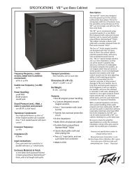
ENGLISHPV ® 35XO 3-<strong>Way</strong> <strong>Stereo</strong>/4-<strong>Way</strong> <strong>or</strong> 5-<strong>Way</strong> <strong>Mono</strong> <strong>Crossover</strong>DescriptionThank you f<strong>or</strong> purchasing a <strong>Peavey</strong> PV 35XO 3-way stereo/4-way <strong>or</strong> 5-way mono crossover. The PV 35XO is a dual-channel modelinc<strong>or</strong>p<strong>or</strong>ating <strong>Peavey</strong>’s legendary low-noise, low-dist<strong>or</strong>tion design. Ruggedly constructed, the PV 35XO gives the operat<strong>or</strong> theflexibility to establish a three-way stereo system <strong>or</strong> run in a four-way and even a five-way mono configuration. The PV 35XO hasvariable state filter controls with 24 dB per octave filters. The PV 35XO utilizes XLR inputs and outputs f<strong>or</strong> balanced operationfrom 20 Hz - 20 kHz.Features➡ 3-way stereo/4-way and 5-way mono operation➡ Variable-state filter controls➡ 24 dB/octave filters➡ Mute capabilities f<strong>or</strong> each output level control➡ XLR inputs and outputs f<strong>or</strong> balanced operation➡ 20 Hz - 20 kHz operation
S T E R E O M O D E O P E R A T I O NF R O N T PA N E L246135 7INPUT GAIN CONTROL (Channel 1) (1)This control is used to optimize channel 1 gain between the mixer and the power amps f<strong>or</strong> channel 1. Thecontrol range is between -12 dB and +12 dB.CLIP INDICATOR (Channel 1) (2)When illuminated, the red Clip indicat<strong>or</strong> located to the upper right of the Input Gain control indicatesthat the signal is clipping. This clipping may be heard as dist<strong>or</strong>tion. While there should be no problem if thisindicat<strong>or</strong> flashes occasionally, it should never flash constantly <strong>or</strong> stay illuminated. This could result in impairedsystem perf<strong>or</strong>mance and possible loudspeaker damage.CROSSOVER SELECTOR CONTROL (Channel 1 lows/mids) (3)This allows users to choose their desired crossover points f<strong>or</strong> lows and the low side of the mids f<strong>or</strong> channel1. The control range is between 80 Hz and 900 Hz <strong>or</strong> 800 Hz and 9 kHz, depending on the position of theRange switch.RANGE (x10) SWITCH (Channel 1 lows/mids) (4)This switch multiplies the value indicated on the <strong>Crossover</strong> Select<strong>or</strong> control f<strong>or</strong> the lows and the low side ofthe mids times 10. When engaged, the range will change from 80 Hz - 900 Hz to 800 Hz - 9 kHz. Range x10 isindicated by the illumination of the red LED above the switch.CROSSOVER SELECTOR CONTROL (Channel 1 mids/highs) (5)This allows users to choose their desired crossover points f<strong>or</strong> the high side of the mids and the highs f<strong>or</strong>channel 1. The control range is between 80 Hz and 900 Hz <strong>or</strong> 800 Hz and 9 kHz, depending on the positionof the Range switch.RANGE (x10) SWITCH (Channel 1 mids/highs) (6)This switch multiplies the value indicated on the <strong>Crossover</strong> Select<strong>or</strong> control f<strong>or</strong> the high side of the mids andthe highs times 10. When engaged, the range will change from 80 Hz - 900 Hz to 800 Hz - 9 kHz. Range x10is indicated by the illumination of the red LED above the switch.LOW GAIN CONTROL (Channel 1) (7)This controls the output level of channel 1 low frequency signal (signal below the selected low/mid crossoverpoint) present at the channel 1 low output XLR.
101214168 9111315MID GAIN CONTROL (Channel 1) (8)This controls the output level of the channel 1 mid frequency signal (signal above the selected low/mid crossoverpoint and below the selected mid/high crossover point) present at the channel 1 mid output XLR.HIGH GAIN CONTROL (Channel 1) (9)This controls the output level of the channel 1 high frequency signal (signal above the selected mid/high crossoverpoint) present at the channel 1 high output XLR.OUTPUT MUTE SWITCHES (Channel 1) (10)This mutes the output of the associated level controls. The Mute function will be indicated by the illumination ofthe red LED located above the associated switch.MODE SWITCH (11)This switch selects between stereo 3-way operation and mono 5-way operation. The red LED above the Modeswitch indicates mono mode. When this switch is engaged, the crossover is in mono operation.SUBS OUT SUMMED SWITCH (12)This switch combines the sub frequencies of both channel 1 and channel 2 into a single output, which allows you touse half as many amplifiers as you would with two channels of subs. The Summed function will be indicated by theillumination of the red LED above the switch.INPUT GAIN CONTROL (Channel 2) (13)This control is used to optimize the channel 2 gain between the mixer and the power amps f<strong>or</strong> channel 2. Thecontrol range is between -12 dB and +12 dB.CLIP INDICATOR (Channel 2) (14)When illuminated, the red Clip indicat<strong>or</strong> located to the upper right of the Input Gain control indicates that thesignal is clipping. This clipping may be heard as dist<strong>or</strong>tion. While there should be no problem if this indicat<strong>or</strong> flashesoccasionally, it should never flash constantly <strong>or</strong> stay illuminated. This could result in impaired system perf<strong>or</strong>manceand possible loudspeaker damage.CROSSOVER SELECTOR CONTROL (Channel 2 lows/mids) (15)This allows users to choose their desired crossover points f<strong>or</strong> lows and the low side of the mids f<strong>or</strong> channel 2. Thecontrol range is between 80 Hz and 900 Hz <strong>or</strong> 800 Hz and 9 kHz, depending on the position of the Range switch.RANGE (x10) SWITCH (Channel 2 lows/mids) (16)This switch multiplies the value indicated on the <strong>Crossover</strong> Select<strong>or</strong> control f<strong>or</strong> the lows and the low side ofthe mids times 10. When engaged, the range will change from 80 Hz - 900 Hz to 800 Hz - 9 kHz. Range x10 isindicated by the illumination of the red LED above the switch.
18221719 20 21 23CROSSOVER SELECTOR CONTROL (Channel 2 mids/highs) (17)This allows users to choose their desired crossover points f<strong>or</strong> the high side of the mids and the highs f<strong>or</strong>channel 2. The control range is between 80 Hz and 900 Hz <strong>or</strong> 800 Hz and 9 kHz, depending on the positionof the Range switch.RANGE (x10) SWITCH (Channel 2 mids/highs) (18)This switch multiplies the value indicated on the <strong>Crossover</strong> Select<strong>or</strong> control f<strong>or</strong> the high side of the mids andthe highs times 10. When engaged, the range will change from 80 Hz - 900 Hz to 800 Hz - 9 kHz. Range x10is indicated by the illumination of the red LED above the switch.LOW GAIN CONTROL (Channel 2) (19)This controls the output level of the channel 2 low frequency signal (signal below the selected low/midcrossover point) present at channel 2 low output XLR.MID GAIN CONTROL (Channel 2) (20)This controls the output level of the channel 2 mid frequency signal (signal above the selected low/midcrossover point and below the selected mid/high crossover point) present at channel 2 mid output XLR.HIGH GAIN CONTROL (Channel 2) (21)This controls the output level of channel 2 high frequency signal (signal above the selected mid/high crossoverpoint) present at channel 2 high output XLR.OUTPUT MUTE SWITCHES (Channel 2) (22)This mutes the output of the associated level controls. The Mute function will be indicated by the illuminationof the red LED located above the associated switch.POWER SWITCH (23)This 2-position rocker switch applies mains power to the unit when in the ON position. Power ON isindicated by red LED located above of the Power switch.WARNINGTHE ON/OFF SWITCH IN THIS APPARATUSDOES NOT BREAK BOTH SIDES OF THE MAINS.HAZARDOUS ENERGY MAY BE PRESENT INSIDETHE ENCLOSURE WHEN THE POWER SWITCH ISIN THE OFF POSITION.
R E A R PA N E L9 8 7 6 5 4 3 2 1INPUT (Channel 1) (1)This XLR female 3-pin connect<strong>or</strong> provides a balanced input f<strong>or</strong> channel 1.LOW OUTPUT (Channel 1) (2)This XLR male 3-pin connect<strong>or</strong> provides a balanced output f<strong>or</strong> the low frequencies f<strong>or</strong> channel 1.MID OUTPUT (Channel 1) (3)This XLR male 3-pin connect<strong>or</strong> provides a balanced output f<strong>or</strong> the mid frequencies f<strong>or</strong> channel 1.HIGH OUTPUT (Channel 1) (4)This XLR male 3-pin connect<strong>or</strong> provides a balanced output f<strong>or</strong> the high frequencies f<strong>or</strong> channel 1.INPUT (Channel 2) (5)This XLR female 3-pin connect<strong>or</strong> provides a balanced input f<strong>or</strong> channel 2.LOW OUTPUT (Channel 2) (6)This XLR male 3-pin connect<strong>or</strong> provides a balanced output f<strong>or</strong> the low frequencies f<strong>or</strong> channel 2.MID OUTPUT (Channel 2) (7)This XLR male 3-pin connect<strong>or</strong> provides a balanced output f<strong>or</strong> the mid frequencies f<strong>or</strong> channel 2.HIGH OUTPUT (Channel 2) (8)This XLR male 3-pin connect<strong>or</strong> provides a balanced output f<strong>or</strong> the high frequencies f<strong>or</strong> channel 2.IEC MAINS CONNECTOR (9)This is a standard IEC power connect<strong>or</strong>. An AC mains c<strong>or</strong>d having the appropriate AC plug and ratings f<strong>or</strong> theintended operating voltage is included in the carton.Never break off the ground pin on any equipment. It is provided f<strong>or</strong> your safety. If the outlet used doesnot have a ground pin, a suitable grounding adapter should be used and the third wire should be groundedproperly. To prevent the risk of shock <strong>or</strong> fire hazard, always make sure that the equalizer and all associatedequipment is properly grounded.Inc<strong>or</strong>p<strong>or</strong>ated into this IEC MAINS CONNECTOR is the MAINS FUSE HOLDER. If f<strong>or</strong> any reason you areunable to power up this unit, remove the fuse by pulling out the holder. Check to see if the fuse is operational.If not, then replace with a fuse of the appropriate value and rating. If the fuse continues to fail contact yournearest Certified <strong>Peavey</strong> Service Center.
M O N O M O D E O P E R A T I O NF R O N T PA N E L246135 7INPUT GAIN CONTROL (1)This control is used to optimize the gain between the mixer and the power amps. The control range isbetween -12 dB and +12 dB.CLIP INDICATOR (2)When illuminated, the red Clip indicat<strong>or</strong> located to the upper right of the Input Gain control indicatesthat the signal is clipping. This clipping may be heard as dist<strong>or</strong>tion. While there should be no problem if thisindicat<strong>or</strong> flashes occasionally, it should never flash constantly <strong>or</strong> stay illuminated. This could result in impairedsystem perf<strong>or</strong>mance and possible loudspeaker damage.CROSSOVER SELECTOR CONTROL (lows/low-mids) (3)This allows users to choose their desired crossover points f<strong>or</strong> lows and the low side of the low-mids. Thecontrol range is between 80 Hz and 900 Hz <strong>or</strong> 800 Hz and 9 kHz, depending on the position of the Rangeswitch.RANGE (x10) SWITCH (lows/low-mids) (4)This switch multiplies the value indicated on the <strong>Crossover</strong> Select<strong>or</strong> control f<strong>or</strong> the lows and the low side ofthe low-mids times 10. When engaged, the range will change from 80 Hz - 900 Hz to 800 Hz - 9kHz. Rangex10 is indicated by the illumination of the red LED above the switch.CROSSOVER SELECTOR CONTROL (low-mid/mids) (5)This allows users to choose their desired crossover points f<strong>or</strong> the high side of the low-mids and the low sideof the mids. The control range is between 80 Hz and 900 Hz <strong>or</strong> 800 Hz and 9 kHz, depending on the positionof the Range switch.RANGE (x10) SWITCH (low-mid/mids) (6)This switch multiplies the value indicated on the <strong>Crossover</strong> Select<strong>or</strong> control f<strong>or</strong> the high side of the low-midsand the low side of the mids times 10. When engaged, the range will change from 80 Hz - 900 Hz to 800 Hz- 9 kHz. Range x10 is indicated by the illumination of the red LED above the switch.LOW GAIN CONTROL (7)This controls the output level of the low frequency signal (signal below the selected low/low-mid crossoverpoint) present at low output XLR.
101214168 9111315LOW-MID GAIN CONTROL (8)This controls the output level of the low-mid frequency signal (signal above the selected low/low-mid crossoverpoint and below the selected low-mid/mid crossover point) present at low-mid output XLR.HIGH GAIN CONTROL (Channel 1) (9)This function is non-operational in MONO mode.OUTPUT MUTE SWITCHES (Channel 1) (10)This mutes the output of the associated level controls f<strong>or</strong> lows and low-mids signals. The Mute function will beindicated by the illumination of the red LED located above the associated switch.MODE SWITCH (11)This switch selects between stereo 3-way operation and mono 5-way operation. The red LED above Mode switchindicates mono mode. When the switch is engaged, the crossover is in mono operation.SUBS OUT SUMMED SWITCH (12)This function is non-operational in MONO mode.INPUT GAIN CONTROL (Channel 2) (13)This function is non-operational in MONO mode.CLIP INDICATOR (Channel 2) (14)This function is non-operational in MONO mode.CROSSOVER SELECTOR CONTROL (mids/high-mids) (15)This allows users to choose their desired crossover points f<strong>or</strong> the high side of the mids and the low side of thehigh-mids. The control range is between 80 Hz and 900 Hz <strong>or</strong> 800 Hz and 9 kHz, depending on the position of theRange switch.RANGE (x10) SWITCH (mids/high-mids) (16)This switch multiplies the value indicated on the <strong>Crossover</strong> Select<strong>or</strong> control f<strong>or</strong> the high side of the mids and thelow side of the high-mids times 10. When engaged, the range will change from 80 Hz - 900 Hz to 800 Hz - 9 kHz.Range x10 is indicated by the illumination of the red LED above the switch.
18221719 20 21 23CROSSOVER SELECTOR CONTROL (high-mids/highs) (17)This allows users to choose their desired crossover points f<strong>or</strong> the high side of the high-mids and the highs. Thecontrol range is between 80 Hz and 900 Hz <strong>or</strong> 800 Hz and 9 kHz, depending on the position of the Range switch.RANGE (x10) SWITCH (high-mids/highs) (18)This switch multiplies the value indicated on the <strong>Crossover</strong> Select<strong>or</strong> control f<strong>or</strong> the high side of the high-mids andthe highs times 10. When engaged, the range will change from 80 Hz - 900 Hz to 800 Hz - 9 kHz. Range x10 isindicated by the illumination of the red LED above the switch.MID GAIN CONTROL (19)This controls the output level of the mid frequency signal (signal above the selected low-mid/mid crossover pointand below the selected mid/high-mid crossover point) present at mid output XLR.HIGH-MID GAIN CONTROL (20)This controls the output level of the high-mid frequency signal (signal above the selected high-mid/mid crossoverpoint and below the selected high crossover point) present at high-mid output XLR.HIGH GAIN CONTROL (21)This controls the output level of high frequency signal (signal above the selected high-mid/high crossover point)present at high output XLR.OUTPUT MUTE SWITCHES (Channel 2) (22)This mutes the output of the associated level controls. The Mute function will be indicated by the illumination ofthe red LED located above the associated switch.POWER SWITCH (23)This 2-position rocker switch applies mains power to the unit when in the ON position. Power ON is indicated byred LED located above the Power Switch.WARNINGTHE ON/OFF SWITCH IN THIS APPARATUSDOES NOT BREAK BOTH SIDES OF THE MAINS.HAZARDOUS ENERGY MAY BE PRESENT INSIDETHE ENCLOSURE WHEN THE POWER SWITCH ISIN THE OFF POSITION.
R E A R PA N E L9 8 7 6 5 4 3 2 1INPUT (1)This XLR female 3-pin connect<strong>or</strong> provides a balanced input.LOW OUTPUT (2)This XLR male 3-pin connect<strong>or</strong> provides a balanced output f<strong>or</strong> the low frequencies.LOW-MID OUTPUT (3)This XLR male 3-pin connect<strong>or</strong> provides a balanced output f<strong>or</strong> the low side of the mid frequencies.HIGH OUTPUT (Channel 1) (4)This function is non-operational in MONO mode.INPUT (Channel 2) (5)This function is non-operational in MONO mode.MID OUTPUT (6)This XLR male 3-pin connect<strong>or</strong> provides a balanced output f<strong>or</strong> the mid frequencies.HIGH-MID OUTPUT (7)This XLR male 3-pin connect<strong>or</strong> provides a balanced output f<strong>or</strong> the high side of the mid frequencies.HIGH OUTPUT (8)This XLR male 3-pin connect<strong>or</strong> provides a balanced output f<strong>or</strong> the high frequencies.IEC MAINS CONNECTOR (9)This is a standard IEC power connect<strong>or</strong>. An AC mains c<strong>or</strong>d having the appropriate AC plug and ratings f<strong>or</strong> theintended operating voltage is included in the carton.Never break off the ground pin on any equipment. It is provided f<strong>or</strong> your safety. If the outlet used doesnot have a ground pin, a suitable grounding adapter should be used and the third wire should be groundedproperly. To prevent the risk of shock <strong>or</strong> fire hazard, always make sure that the equalizer and all associatedequipment is properly grounded.Inc<strong>or</strong>p<strong>or</strong>ated into this IEC MAINS CONNECTOR is the MAINS FUSE HOLDER. If f<strong>or</strong> any reason you areunable to power up this unit, remove the fuse by pulling out the holder. Check to see if the fuse is operational.If not, then replace with a fuse of the appropriate value and rating. If the fuse continues to fail contact yournearest Certified <strong>Peavey</strong> Service Center.
PV ® 35XO3-<strong>Way</strong> <strong>Stereo</strong>/4-<strong>Way</strong> <strong>or</strong> 5-<strong>Way</strong> <strong>Mono</strong> <strong>Crossover</strong>SPECIFICATIONSBandwidth: 20 Hz - 20 kHzFrequency Response: 20 Hz - 20 kHz +/- 1 dBTHD: 20 Hz - 20 kHz .005 dB %Signal to Noise: -92 dBFilter Type: 24 dB/OctaveVariable State Control Range:Low/MidMid/HighLow/Low-MidLow-Mid/MidMid/High-MidHigh-Mid/High<strong>Stereo</strong> ModeRange x1 = 80 Hz - 900 HzRange x10 = 800 Hz - 9 kHzRange x1 = 80 Hz - 900 HzRange x10 = 800 Hz - 9 kHz<strong>Mono</strong> ModeRange x1 = 80 Hz - 900 HzRange x10 = 800 Hz - 9 kHzRange x1 = 80 Hz - 900 HzRange x10 = 800 Hz - 9 kHzRange x1 = 80 Hz - 900 HzRange x10 = 800 Hz - 9 kHzRange x1 = 80 Hz - 900 HzRange x10 = 800 Hz - 9 kHz
DEUTSCHPV ® 35XO 3-Wege-<strong>Stereo</strong>-/4-Wege- oder 5-Wege-<strong>Mono</strong>-FrequenzweicheBeschreibungVielen Dank, dass Sie sich für die <strong>Peavey</strong> PV 35XO 3-Wege-<strong>Stereo</strong>-/4-Wege- oder 5-Wege-<strong>Mono</strong>-Frequenzweiche entschiedenhaben. Die PV 35XO ist ein Zweikanal-Modell in <strong>Peavey</strong>s legendärem geräusch- und verzerrungsarmen Design. Die robustkonstruierte PV 35XO bietet dem Benutzer die Möglichkeit, entweder ein 3-Wege-<strong>Stereo</strong>- oder ein 4-Wege- oder sogar 5-Wege-<strong>Mono</strong>system aufzubauen. Die PV 35XO besitzt variable Filterregler mit Filtern von 24 dB pro Oktave und verwendet XLR-Eingängeund -Ausgänge für symmetrierten Betrieb zwischen 20 Hz und 20 kHz.Merkmale➡ 3-Wege-<strong>Stereo</strong>-/4-Wege- und 5-Wege-<strong>Mono</strong>-Betrieb➡ Variable Filterregler➡ 24 dB/Oktave-Filter➡ Stummschaltung für jeden Ausgangspegelregler➡ XLR-Eingänge und -Ausgänge für symmetrierten Betrieb➡ Betrieb zwischen 20 Hz und 20 kHz
S T E R E O - B E T R I E BV O R D E R S E I T E246135 7INPUT-GAIN-REGLER (Kanal 1) (1)Mit diesem Regler lässt sich der Kanal-1-Gain zwischen Mischpult und Verstärkern für Kanal 1 optimieren. DerRegelbereich beträgt -12 dB bis +12 dB.CLIP-ANZEIGE (Kanal 1) (2)Die rote Clip-Anzeige rechts oberhalb des Eingangs-Gain-Reglers leuchtet auf, wenn ein Signal-Clippingv<strong>or</strong>liegt. Dieses Clipping-Signal kann als Verzerrung zu vernehmen sein. Es ist n<strong>or</strong>mal, wenn diese Anzeigegelegentlich aufleuchtet, sie sollte jedoch nicht ständig blinken oder leuchten, da dies zu Lasten derSystemleistung geht und die Lautsprecher beschädigt werden können.CROSSOVER-WAHLSCHALTER (Kanal 1 Tiefen/Mitten) (3)Gestattet dem Anwender die Auswahl der gewünschten Übergangsfrequenzen für die Bässe und die Tiefmittenvon Kanal 1. Je nach Stellung des Bereichs-Schalters liegt der Regelbereich zwischen 80 Hz und 900 Hz oder800 Hz und 9 kHz.RANGE-SCHALTER (x10) (Kanal 1 Tiefen/Mitten) (4)Ist dieser Schalter aktiviert, verzehnfacht sich der am CROSSOVER-Wahlschalter angezeigte Wert der Bässeund Tiefmitten. In diesem Fall ändert sich der Bereich von 80 Hz bis 900 Hz auf 800 Hz bis 9 kHz. Wenn„Range x10“ aktiv ist, leuchtet die rote LED über dem Schalter.CROSSOVER-WAHLSCHALTER (Kanal 1 Mitten/Höhen) (5)Gestattet dem Anwender die Auswahl der gewünschten Übergangsfrequenzen für die Hochmitten und dieHöhen von Kanal 1. Je nach Stellung des Bereichs-Schalters liegt der Regelbereich zwischen 80 Hz und 900 Hzoder 800 Hz und 9 kHz.RANGE-SCHALTER (x10) (Kanal 1 Mitten/Höhen) (6)Ist dieser Schalter aktiviert, verzehnfacht sich der am CROSSOVER-Wahlschalter angezeigte Wert derHochmitten und der Höhen. In diesem Fall ändert sich der Bereich von 80 Hz bis 900 Hz auf 800 Hz bis 9kHz. Wenn „Range x10“ aktiv ist, leuchtet die rote LED über dem Schalter.LOW-GAIN-REGLER (Kanal 1) (7)Regelt den Ausgangspegel des niederfrequenten Signals von Kanal 1 (Signal unter der gewählten Tiefmitten-Übergangsfrequenz) am XLR-Tiefenausgang von Kanal 1.
1012148 9111315MID-GAIN-REGLER (Kanal 1) (8)Regelt den Ausgangspegel des mittelfrequenten Signals von Kanal 1 (Signal über der gewählten Tiefmitten- undunter der gewählten Hochmitten-Übergangsfrequenz) am XLR-Mittenausgang von Kanal 1.HIGH-GAIN-REGLER (Kanal 1) (9)Regelt den Ausgangspegel des hochfrequenten Signals von Kanal 1 (Signal über der gewählten Hochmitten-Übergangsfrequenz) am XLR-Höhenausgang von Kanal 1.OUTPUT-MUTE-SCHALTER (Kanal 1) (10)Mit diesen Schaltern wird der Ausgang der entsprechenden Pegelregler stumm geschaltet. Wenn Mute aktiv ist,leuchtet die rote LED über dem jeweiligen Schalter.MODE-SCHALTER (11)Mit diesem Schalter wählen Sie zwischen 3-Wege-<strong>Stereo</strong>- oder 5-Wege-<strong>Mono</strong>-Betrieb. Die rote LED über demMode-Schalter zeigt an, dass der <strong>Mono</strong>-Modus gewählt ist. Wenn der Schalter aktiviert ist, befindet sich dieFrequenzweiche im <strong>Mono</strong>-Betrieb.SUBS-OUT-GESAMTSCHALTER (12)Mit diesem Schalter kombinieren die Sub-Frequenzen von Kanal 1 und Kanal 2 in einem gemeinsamen Ausgang,sodass nur halb so viele Verstärker wie bei zwei Sub-Kanälen notwendig sind. Wenn diese Funktion aktiv ist, leuchtetdie rote LED über dem Schalter.INPUT-GAIN-REGLER (Kanal 2) (13)Mit diesem Regler lässt sich der Kanal-2-Gain zwischen Mischpult und Verstärkern für Kanal 2 optimieren. DerRegelbereich beträgt -12 dB bis +12 dB.CLIP-ANZEIGE (Kanal 2) (14)Die rote Clip-Anzeige rechts oberhalb des Eingangs-Gain-Reglers leuchtet auf, wenn ein Signal-Clipping v<strong>or</strong>liegt.Dieses Clipping-Signal kann als Verzerrung zu vernehmen sein. Es ist n<strong>or</strong>mal, wenn diese Anzeige gelegentlichaufleuchtet, sie sollte jedoch nicht ständig blinken oder leuchten, da dies zu Lasten der Systemleistung geht und dieLautsprecher beschädigt werden können.CROSSOVER-WAHLSCHALTER (Kanal 2 Tiefen/Mitten) (15)Gestattet dem Anwender die Auswahl der gewünschten Übergangsfrequenzen für die Bässe und Tiefmitten vonKanal 2. Je nach Stellung des Bereichs-Schalters liegt der Regelbereich zwischen 80 Hz und 900 Hz oder 800 Hzund 9 kHz.
1618221719 20 21 23RANGE-SCHALTER (x10) (Kanal 2 Tiefen/Mitten) (16)Ist dieser Schalter aktiviert, verzehnfacht sich der am CROSSOVER-Wahlschalter angezeigte Wert der Bässeund der Tiefmitten. In diesem Fall ändert sich der Bereich von 80 Hz bis 900 Hz auf 800 Hz bis 9 kHz. Wenn„Range x10“ aktiv ist, leuchtet die rote LED über dem Schalter.CROSSOVER-WAHLSCHALTER (Kanal 2 Mitten/Höhen) (17)Gestattet dem Anwender die Auswahl der gewünschten Übergangsfrequenzen für die Hochmitten und dieHöhen von Kanal 2. Je nach Stellung des Bereichs-Schalters liegt der Regelbereich zwischen 80 Hz und 900 Hzoder 800 Hz und 9 kHz.RANGE-SCHALTER (x10) (Kanal 2 Mitten/Höhen) (18)Ist dieser Schalter aktiviert, verzehnfacht sich der am CROSSOVER-Wahlschalter angezeigte Wert derHochmitten und der Höhen. In diesem Fall ändert sich der Bereich von 80 Hz bis 900 Hz auf 800 Hz bis 9kHz. Wenn „Range x10“ aktiv ist, leuchtet die rote LED über dem Schalter.LOW-GAIN-REGLER (Kanal 2) (19)Regelt den Ausgangspegel des niederfrequenten Signals von Kanal 2 (Signal unter der gewählten Tiefmitten-Übergangsfrequenz) am XLR-Tiefenausgang von Kanal 2.MID-GAIN-REGLER (Kanal 2) (20)Regelt den Ausgangspegel des mittelfrequenten Signals von Kanal 2 (Signal über der gewählten Tiefmitten- undunter der gewählten Mitten-Höhen-Übergangsfrequenz) am XLR-Mittenausgang von Kanal 2.HIGH-GAIN-REGLER (Kanal 2) (21)Regelt den Ausgangspegel des hochfrequenten Signals von Kanal 2 (Signal über der gewählten Hochmitten-Übergangsfrequenz) am XLR-Höhenausgang von Kanal 2.OUTPUT-MUTE-SCHALTER (Kanal 2) (22)Mit diesem Schalter wird der Ausgang der entsprechenden Pegelregler stumm geschaltet. Wenn Mute aktiv ist,leuchtet die rote LED über dem Schalter.POWER-SCHALTER (23)Steht dieser Kippschalter mit 2 Stellungen aufON, wird das Gerät mit Netzstrom vers<strong>or</strong>gt.Die rote LED über dem Netzschalter zeigt an,dass das Gerät am Netz ist (ON).WARNUNGDER AN/AUS SCHALTER IN DIESEM GERÄT UNTERBRICHTNICHT BEIDE SEITEN DES NETZES. AUCH WENN DERSCHALTER AUF "AUS" STEHT KANN IM INNERN DESGERÄTES IMMER NOCH GEFÄHRLICHE ELEKTRISCHEENERGIEN VORHANDEN SEIN.
R Ü C K S E I T E8 7 6 5 4 3 2 1INPUT (Kanal 1) (1)Diese 3-Pin-Buchse (XLR-female) s<strong>or</strong>gt für einen symmetrierten Eingang für Kanal 1.LOW OUTPUT (Kanal 1) (2)Diese 3-Pin-Buchse (XLR-male) s<strong>or</strong>gt für einen symmetrierten Ausgang der niedrigen Frequenzen für Kanal 1.MID OUTPUT (Kanal 1) (3)Diese 3-Pin-Buchse (XLR-male) s<strong>or</strong>gt für einen symmetrierten Ausgang der Mittelfrequenzen für Kanal 1.HIGH OUTPUT (Kanal 1) (4)Diese 3-Pin-Buchse (XLR-male) s<strong>or</strong>gt für einen symmetrierten Ausgang der hohen Frequenzen für Kanal 1.INPUT (Kanal 2) (5)Diese 3-Pin-Buchse (XLR-female) s<strong>or</strong>gt für einen symmetrierten Eingang für Kanal 2.LOW OUTPUT (Kanal 2) (6)Diese 3-Pin-Buchse (XLR-male) s<strong>or</strong>gt für einen symmetrierten Ausgang der niedrigen Frequenzen für Kanal 2.MID OUTPUT (Kanal 2) (7)Diese 3-Pin-Buchse (XLR-male) s<strong>or</strong>gt für einen symmetrierten Ausgang der Mittelfrequenzen für Kanal 2.HIGH OUTPUT (Kanal 2) (8)Diese 3-Pin-Buchse (XLR-male) s<strong>or</strong>gt für einen symmetrierten Ausgang der hohen Frequenzen für Kanal 2.
9IEC-NETZSTECKER (9)Hierbei handelt es sich um einen gen<strong>or</strong>mten IEC-Netzstecker. Ein Wechselstrom-Netzkabel mitdem entsprechenden Wechselstromstecker und den entsprechenden Werten für die erf<strong>or</strong>derlicheBetriebsspannung liegt bei.Der Erdungsstift eines Geräts darf keinesfalls entfernt werden. Er ist zu Ihrer Sicherheit v<strong>or</strong>handen. Fehlt derErdungsstift an der verwendeten Steckdose, muss ein geeigneter Erdungsadapter verwendet und die dritteAder k<strong>or</strong>rekt geerdet werden. Um elektrische Schläge oder Brände auszuschließen, müssen der Equalizersowie sämtliche zugehörigen Ausrüstungsteile k<strong>or</strong>rekt geerdet werden.In den IEC-NETZSTECKER ist der NETZSICHERUNGSHALTER integriert. Lässt sich dieses Gerät ausirgendeinem Grund nicht einschalten, entfernen Sie die Sicherung, indem Sie den Halter herausziehen.Überprüfen Sie, ob die Sicherung betriebsbereit ist. Ist dies nicht der Fall, ersetzen Sie diese Sicherung durcheine Sicherung gleichen Typs mit dem gleichen Wert. Sollte die Sicherung weiter Probleme bereiten, wendenSie sich an ein zugelassenes <strong>Peavey</strong>-Service-Center in Ihrer Nähe.
M O N O - B E T R I E BV O R D E R S E I T E246135 7INPUT-GAIN-REGLER (1)Mit diesem Regler lässt sich der Gain zwischen Mischpult und Verstärkern für Kanal 1 optimieren. DerRegelbereich beträgt -12 dB bis +12 dB.CLIP-ANZEIGE (2)Die rote Clip-Anzeige rechts oberhalb des Eingangs-Gain-Reglers leuchtet auf, wenn ein Signal-Clippingv<strong>or</strong>liegt. Dieses Clipping-Signal kann als Verzerrung zu vernehmen sein. Es ist n<strong>or</strong>mal, wenn diese Anzeigegelegentlich aufleuchtet, sie sollte jedoch nicht ständig blinken oder leuchten, da dies zu Lasten derSystemleistung geht und die Lautsprecher beschädigt werden können.CROSSOVER-WAHLSCHALTER (Tiefen/tiefe Mitten) (3)Gestattet dem Anwender die Auswahl der gewünschten Übergangsfrequenzen für die Tiefen und dieTiefmitten. Je nach Stellung des Bereichs-Schalters liegt der Regelbereich zwischen 80 Hz und 900 Hz oder800 Hz und 9 kHz.RANGE-SCHALTER (x10) (Tiefen/tiefe Mitten) (4)Ist dieser Schalter aktiviert, verzehnfacht sich der am CROSSOVER-Wahlschalter angezeigte Wert der Tiefenund der Tiefmitten. In diesem Fall ändert sich der Bereich von 80 Hz bis 900 Hz auf 800 Hz bis 9 kHz. Wenn„Range x10“ aktiv ist, leuchtet die rote LED über dem Schalter.CROSSOVER-WAHLSCHALTER (tiefe Mitten/Mitten) (5)Gestattet dem Anwender die Auswahl der gewünschten Übergangsfrequenzen für die Hochmitten und dieTiefmitten. Je nach Stellung des Bereichs-Schalters liegt der Regelbereich zwischen 80 Hz und 900 Hz oder800 Hz und 9 kHz.RANGE-SCHALTER (x10) (tiefe Mitten/Mitten) (6)Ist dieser Schalter aktiviert, verzehnfacht sich der am CROSSOVER-Wahlschalter angezeigte Wert derHochmitten und der Tiefmitten. In diesem Fall ändert sich der Bereich von 80 Hz bis 900 Hz auf 800 Hz bis 9kHz. Wenn „Range x10“ aktiv ist, leuchtet die rote LED über dem Schalter.LOW-GAIN-REGLER (7)Regelt den Ausgangspegel des niederfrequenten Signals (Signal unter der gewählten Tiefen-/tiefe Mitten-Übergangsfrequenz) am XLR-Tiefenausgang.
101214168 9111315LOW-MID-GAIN-REGLER (8)Regelt den Ausgangspegel des tiefen mittelfrequenten Signals (Signal über der gewählten Tiefen-/Mitten- und unterder gewählten Tiefmitten-/Mitten-Übergangsfrequenz) am XLR-Ausgang der tiefen Mitten.HIGH-GAIN-REGLER (Kanal 1) (9)Diese Funktion steht im MONO-Modus nicht zur Verfügung.OUTPUT-MUTE-SCHALTER (Kanal 1) (10)Mit diesem Schalter wird der Ausgang der entsprechenden Pegelregler für Tiefen und tiefe Mittensignale stummgeschaltet. Wenn Mute aktiv ist, leuchtet die rote LED über dem Schalter.MODE-SCHALTER (11)Mit diesem Schalter wählen Sie zwischen 3-Wege-<strong>Stereo</strong>- oder 5-Wege-<strong>Mono</strong>-Betrieb. Die rote LED über demMode-Schalter zeigt an, dass der <strong>Mono</strong>-Modus gewählt ist. Wenn der Schalter aktiviert ist, befindet sich dieFrequenzweiche im <strong>Mono</strong>-Betrieb.SUBS-OUT-GESAMTSCHALTER (12)Diese Funktion steht im MONO-Modus nicht zur Verfügung.INPUT-GAIN-REGLER (Kanal 2) (13)Diese Funktion steht im MONO-Modus nicht zur Verfügung.CLIP-ANZEIGE (Kanal 2) (14)Diese Funktion steht im MONO-Modus nicht zur Verfügung.CROSSOVER-WAHLSCHALTER (Mitten/hohe Mitten) (15)Gestattet dem Anwender die Auswahl der gewünschten Übergangsfrequenzen für die Hochmitten und dieTiefmitten. Je nach Stellung des Bereichs-Schalters liegt der Regelbereich zwischen 80 Hz und 900 Hz oder 800 Hzund 9 kHz.RANGE-SCHALTER (x10) (Mitten/hohe Mitten) (16)Ist dieser Schalter aktiviert, verzehnfacht sich der am CROSSOVER-Wahlschalter angezeigte Wert der Hochmittenund der tiefere Bereich der hohen Mitten. In diesem Fall ändert sich der Bereich von 80 Hz bis 900 Hz auf 800 Hzbis 9 kHz. Wenn „Range x10“ aktiv ist, leuchtet die rote LED über dem Schalter.
18221719 20 21 23CROSSOVER-WAHLSCHALTER (hohe Mitten/Höhen) (17)Gestattet dem Anwender die Auswahl der gewünschten Übergangsfrequenzen für den höheren Bereich derHochmitten und die Höhen. Je nach Stellung des Bereichs-Schalters liegt der Regelbereich zwischen 80 Hz und 900Hz oder 800 Hz und 9 kHz.RANGE-SCHALTER (x10) (hohe Mitten/Höhen) (18)Ist dieser Schalter aktiviert, verzehnfacht sich der am CROSSOVER-Wahlschalter angezeigte Wert des höherenBereichs der Hochmitten und der Höhen. In diesem Fall ändert sich der Bereich von 80 Hz bis 900 Hz auf 800 Hzbis 9 kHz. Wenn „Range x10“ aktiv ist, leuchtet die rote LED über dem Schalter.MID-GAIN-REGLER (19)Regelt den Ausgangspegel des mittelfrequenten Signals (Signal über der gewählten Tiefmitten-/Mitten- und unter dergewählten Mitten-/Hochmitten-Übergangsfrequenz) am XLR-Mittenausgang.HIGH-MID-GAIN-REGLER (20)Regelt den Ausgangspegel des hohen mittelfrequenten Signals (Signal über der gewählten Hochmitten-/Mitten- undunter der gewählten Höhen-Übergangsfrequenz) am XLR-Ausgang der hohen Mitten.HIGH-GAIN-REGLER (21)Regelt den Ausgangspegel des hochfrequenten Signals (Signal über der gewählten Hochmitten-/Höhen-Übergangsfrequenz) am XLR-Höhenausgang.OUTPUT-MUTE-SCHALTER (Kanal 2) (22)Mit diesen Schaltern wird der Ausgang der entsprechenden Pegelregler stumm geschaltet. Wenn Mute aktiv ist,leuchtet die rote LED über dem jeweiligen Schalter.POWER-SCHALTER (23)Steht dieser Kippschalter mit 2 Stellungen auf ON, wird das Gerät mit Netzstrom vers<strong>or</strong>gt. Die rote LED überdem Netzschalter zeigt an, dass das Gerät am Netz ist (ON).WARNUNGDER AN/AUS SCHALTER IN DIESEM GERÄT UNTERBRICHTNICHT BEIDE SEITEN DES NETZES. AUCH WENN DERSCHALTER AUF "AUS" STEHT KANN IM INNERN DESGERÄTES IMMER NOCH GEFÄHRLICHE ELEKTRISCHEENERGIEN VORHANDEN SEIN.
R Ü C K S E I T E8 7 6 5 4 3 2 1INPUT (Kanal 1) (1)Diese 3-Pin-Buchse (XLR-female) s<strong>or</strong>gt für einen symmetrierten Eingang für Kanal 1.LOW OUTPUT (Kanal 1) (2)Diese 3-Pin-Buchse (XLR-male) s<strong>or</strong>gt für einen symmetrierten Ausgang der niedrigen Frequenzen für Kanal 1.MID OUTPUT (Kanal 1) (3)Diese 3-Pin-Buchse (XLR-male) s<strong>or</strong>gt für einen symmetrierten Ausgang der Mittelfrequenzen für Kanal 1.HIGH OUTPUT (Kanal 1) (4)Diese Funktion steht beim <strong>Mono</strong>-Betrieb nicht zur Verfügung.INPUT (Kanal 2) (5)Diese Funktion steht beim <strong>Mono</strong>-Betrieb nicht zur Verfügung.LOW OUTPUT (Kanal 2) (6)Diese 3-Pin-Buchse (XLR-male) s<strong>or</strong>gt für einen symmetrierten Ausgang der niedrigen Frequenzen für Kanal 2.MID OUTPUT (Kanal 2) (7)Diese 3-Pin-Buchse (XLR-male) s<strong>or</strong>gt für einen symmetrierten Ausgang der Mittelfrequenzen für Kanal 2.HIGH OUTPUT (Kanal 2) (8)Diese 3-Pin-Buchse (XLR-male) s<strong>or</strong>gt für einen symmetrierten Ausgang der hohen Frequenzen für Kanal 2.
9IEC-NETZSTECKER (9)Hierbei handelt es sich um einen gen<strong>or</strong>mten IEC-Netzstecker. Ein Wechselstrom-Netzkabel mitdem entsprechenden Wechselstromstecker und den entsprechenden Werten für die erf<strong>or</strong>derlicheBetriebsspannung liegt bei.Der Erdungsstift eines Geräts darf keinesfalls entfernt werden. Er ist zu Ihrer Sicherheit v<strong>or</strong>handen. Fehlt derErdungsstift an der verwendeten Steckdose, muss ein geeigneter Erdungsadapter verwendet und die dritteAder k<strong>or</strong>rekt geerdet werden. Um elektrische Schläge oder Brände auszuschließen, müssen der Equalizersowie sämtliche zugehörigen Ausrüstungsteile k<strong>or</strong>rekt geerdet werden.In den IEC-NETZSTECKER ist der NETZSICHERUNGSHALTER integriert. Lässt sich dieses Gerät ausirgendeinem Grund nicht einschalten, entfernen Sie die Sicherung, indem Sie den Halter herausziehen.Überprüfen Sie, ob die Sicherung betriebsbereit ist. Ist dies nicht der Fall, ersetzen Sie diese Sicherung durcheine Sicherung gleichen Typs mit dem gleichen Wert. Sollte die Sicherung weiter Probleme bereiten, wendenSie sich an ein zugelassenes <strong>Peavey</strong>-Service-Center in Ihrer Nähe.
PV ® 35XO3-Wege-<strong>Stereo</strong>/4-Wege- oder 5-Wege-<strong>Mono</strong>-FrequenzweicheTECHNISCHE DATENBandbreite: 20 Hz - 20 kHzFrequenzverhalten: 20 Hz - 20 kHz +/- 1 dBTHD: 20 Hz - 20 kHz .005 dB %Rauschabstand: -92 dBFiltertyp: 24 dB/OktaveVariabler Regelbereich:Tiefen/MittenMitten/HöhenTiefen/niedrige MittenTiefe Mitten/MittenMitten/Hohe MittenHohe Mitten/Höhen<strong>Stereo</strong>-BetriebBereich x1 = 80 Hz - 900 HzBereich x10 = 800 Hz - 9 kHzBereich x1 = 80 Hz - 900 HzBereich x10 = 800 Hz - 9 kHz<strong>Mono</strong>-BetriebBereich x1 = 80 Hz - 900 HzBereich x10 = 800 Hz - 9 kHzBereich x1 = 80 Hz - 900 HzBereich x10 = 800 Hz - 9 kHzBereich x1 = 80 Hz - 900 HzBereich x10 = 800 Hz - 9 kHzBereich x1 = 80 Hz - 900 HzBereich x10 = 800 Hz - 9 kHz
FRANÇAISPV ® 35XO Filtre actif 3-voies stéréo/5-voies monoDescriptionMerci d’avoir choisi le filtre actif PV 35XO de <strong>Peavey</strong> Electronics. Le PV 35XO est un filtre actif dans la lignée des produits<strong>Peavey</strong>, avec de faibles niveau de bruit et taux de dist<strong>or</strong>tion, le tout dans une unité de construction solide et pratique. Capable defonctionner tout aussi bien comme un filtre 3-voies stéréo ou comme un filtre 5-voies mono, muni d’entrées et s<strong>or</strong>ties symétriséeset de filtre à 24dB de pente, le PV 35XO est idéal pour de nombreuses applications.Caractéristiques➡ Filtre 3-voies stéréo/5-voies mono➡ Filtres à fréquence variable➡ Pente de filtre de 24 dB/octave➡ Entrées et s<strong>or</strong>ties XLR pour signal symétrisé➡ Mode silence (Mute) pour chaque contrôle de s<strong>or</strong>tie➡ Gamme de fréquences de 20 Hz à 20 kHz
M O D E S T E R E OPA N N E A U A V A N T246135 7CONTROLE DE GAIN D’ENTREE (Canal 1) (1)Ce contrôle vous permet d’optimiser le gain du signal du canal 1 pour les étages de puissance. Il permet unealtération de 0 à +12dB.INDICATEUR D’ECRETAGE (CLIP Canal 1) (2)Quand illuminé, l’indicateur rouge à l’extrémité ddu gain d’entrée vous indique la présence d’écrètage.Cet écrètage peut même être entendu comme une dist<strong>or</strong>tion du signal. Bien qu’un flash occasionel de cetindicateur est tolérable, il ne devrait en aucun cas resté illuminé de facon constante. Un écrètage continu setraduit toujours par des dommages au système de diffusion.CONTROLE DE LA FREQUENCE DE FILTRE (Canal 1 Grave/Médium) (3)Ce contrôle vous permet de choisir la fréquence de coupure entre les deux gammes de fréquences (graveset médium). L’échelonnage est entre 80 Hz et 900 Hz ou 800 kHz et 9 kHz selon la position du sélecteur defiltre (4).SELECTEUR DE FILTRE (x10) (Canal 1 Grave/Médium) (4)Ce sélecteur vous permet de choisir la gamme de fréquences de coupure nécessaire à vos enceintes/systèmede diffusion. Le choix est entre de 80 Hz à 900 Hz ou de 800 Hz à 9 kHz. La LED rouge c<strong>or</strong>respondantes’illumine si la seconde est sélectionnée.CONTROLE DE LA FREQUENCE DE FILTRE (Canal 1 Médium/Aigu) (5)Ce contrôle vous permet de choisir la fréquence de coupure entre les deux gammes de fréquences (médiumet aigues). L’échelonnage est entre 80 Hz et 900 Hz ou 800 kHz et 9 kHz selon la position du sélecteur defiltre (6).SELECTEUR DE FILTRE (x10) (Canal 1 Médium/Aigu) (6)Ce sélecteur vous permet de choisir la gamme de fréquences de coupure nécessaire à vos enceintes/systèmede diffusion. Le choix est entre de 80 Hz à 900 Hz ou de 800 Hz à 9 kHz. La LED rouge c<strong>or</strong>respondantes’illumine si la seconde est sélectionnée.CONTROLE DES BASSES FREQUENCES (Canal 1) (7)Ce contrôle vous permet d’optimiser le signal basses-fréquences du canal 1 pour l’envoi à l’étage de puissancec<strong>or</strong>respondant, présent à la s<strong>or</strong>tie XLR annotée ‘low output’ du canal 1.
101214168 9111315CONTROLE DES FREQUENCES MEDIUM (Canal 1) (8)Ce contrôle vous permet d’optimiser le signal fréquences médium du canal 1 pour l’envoi à l’étage de puissancec<strong>or</strong>respondant, présent à la s<strong>or</strong>tie XLR annotée ‘mid output’ du canal 1.CONTROLE DES HAUTES FREQUENCES (Canal 1) (9)Ce contrôle vous permet d’optimiser le signal hautes-fréquences du canal 1 pour l’envoi à l’étage de puissancec<strong>or</strong>respondant, présent à la s<strong>or</strong>tie XLR annotée ‘high output’ du canal 1.INTERRUPTEUR DE MODE SILENCE (MUTE Canal 1) (10)Cet interrupteur vous permet de passer le canal c<strong>or</strong>respondant au contrôle en mode silence. La LED rougec<strong>or</strong>respondante s’illumine pour indiquer l’activation du mode silence.SELECTEUR DE MODE (11)Ce sélecteur vous permet de choisir entre les deux modes de fonctionnement de votre unité: 3-vois stéréo ou 5-voies mono. La LED rouge c<strong>or</strong>respondante s’illumine pour indiquer l’activation du mode mono.SELECTEUR DE SORTIE BASSES FREQUENCES COUPLEES (12)Ce sélecteur vous permet de coupler les gammes de fréquences basses des 2 canaux de votre unité, vouspermettant de réduire le nombre d’amplificateur nécessaire à la difusion. La LED rouge c<strong>or</strong>respondante s’illuminepour indiquer l’activation de la s<strong>or</strong>tie couplée.CONTROLE DE GAIN D’ENTREE (Canal 2) (13)Ce contrôle vous permet d’optimiser le gain du signal du canal 2 pour les étages de puissance. Il permet unealtération de 0 à +12 dB.INDICATEUR D’ECRETAGE (CLIP Canal 2) (14)Quand illuminé, l’indicateur rouge à l’extrémité ddu gain d’entrée vous indique la présence d’écrètage. Cet écrètagepeut même être entendu comme une dist<strong>or</strong>tion du signal. Bien qu’un flash occasionel de cet indicateur esttolérable, il ne devrait en aucun cas resté illuminé de facon constante. Un écrètage continu se traduit toujours pardes dommages au système de diffusion.CONTROLE DE LA FREQUENCE DE FILTRE (Canal 2 Grave/Médium) (15)Ce contrôle vous permet de choisir la fréquence de coupure entre les deux gammes de fréquences (graves etmédium). L’échelonnage est entre 80 Hz et 900 Hz ou 800 kHz et 9 kHz selon la position du sélecteur de filtre(16).SELECTEUR DE FILTRE (x10) (Canal 2 Grave/Médium) (16)Ce sélecteur vous permet de choisir la gamme de fréquences de coupure nécessaire à vos enceintes/système dediffusion. Le choix est entre de 80 Hz à 900 Hz ou de 800 Hz à 9 kHz. La LED rouge c<strong>or</strong>respondante s’illumine sila seconde est sélectionnée.
18221719 20 21 23CONTROLE DE LA FREQUENCE DE FILTRE (Canal 2 Médium/Aigu) (17)Ce contrôle vous permet de choisir la fréquence de coupure entre les deux gammes de fréquences (médiumet aigues). L’échelonnage est entre 80 Hz et 900 Hz ou 800 kHz et 9 kHz selon la position du sélecteur defiltre (18).SELECTEUR DE FILTRE (x10) (Canal 2 Médium/Aigu) (18)Ce sélecteur vous permet de choisir la gamme de fréquences de coupure nécessaire à vos enceintes/systèmede diffusion. Le choix est entre de 80 Hz à 900 Hz ou de 800 Hz à 9 kHz. La LED rouge c<strong>or</strong>respondantes’illumine si la seconde est sélectionnée.CONTROLE DES BASSES FREQUENCES (Canal 2) (19)Ce contrôle vous permet d’optimiser le signal basses-fréquences du canal 2 pour l’envoi à l’étage de puissancec<strong>or</strong>respondant, présent à la s<strong>or</strong>tie XLR annotée ‘low output’ du canal 2.CONTROLE DES FREQUENCES MEDIUM (Canal 2) (20)Ce contrôle vous permet d’optimiser le signal fréquences médium du canal 2 pour l’envoi à l’étage depuissance c<strong>or</strong>respondant, présent à la s<strong>or</strong>tie XLR annotée ‘mid output’ du canal 2.CONTROLE DES HAUTES FREQUENCES (Canal 2) (21)Ce contrôle vous permet d’optimiser le signal hautes-fréquences du canal 2 pour l’envoi à l’étage depuissance c<strong>or</strong>respondant, présent à la s<strong>or</strong>tie XLR annotée ‘high output’ du canal 2.INTERRUPTEUR DE MODE SILENCE (MUTE Canal 2) (22)Cet interrupteur vous permet de passer le canal c<strong>or</strong>respondant au contrôle en mode silence. La LED rougec<strong>or</strong>respondante s’illumine pour indiquer l’activation du mode silence.INTERRUPTEUR D’ALIMENTATION (23)Cet interrupteur permet de mettre votre unité sous/h<strong>or</strong>s tension. Votre unité est active l<strong>or</strong>sque cetinterrupteur est sur la position annotée ON, la LED rouge c<strong>or</strong>respondante illuminée.ATTENTIONL'INTERRUPTEUR D'ALIMENTATION NE COUPE PASCELLE-CI AUX DEUX BORNES ET DE L'ENERGIEELECTRIQUE PEUT ETRE PRESENTE DANS CERTAINSCOMPOSANTS APRES LA MISE HORS-TENSION.
PA N N E A U A R R I E R E8 7 6 5 4 3 2 1ENTREE (Canal 1) (1)Ce connecteur XLR femelle est symétrisé et vous permet d’envoyer le signal audio au canal 1.SORTIE BASSES-FREQUENCES (Canal 1) (2)Ce connecteur mâle XLR vous permet d’envoyer le signal basses-fréquences du canal 1 vers l’étage depuissance c<strong>or</strong>respondant.SORTIE FREQUENCES MEDIUM (Canal 1) (3)Ce connecteur mâle XLR vous permet d’envoyer le signal des fréquences médium du canal 1 vers l’étage depuissance c<strong>or</strong>respondant.SORTIE HAUTES-FREQUENCES (Canal 1) (4)Ce connecteur mâle XLR vous permet d’envoyer le signal hautes-fréquences du canal 1 vers l’étage depuissance c<strong>or</strong>respondant.ENTREE (Canal 2) (5)Ce connecteur XLR femelle est symétrisé et vous permet d’envoyer le signal audio au canal 2.SORTIE BASSES-FREQUENCES (Canal 2) (6)Ce connecteur mâle XLR vous permet d’envoyer le signal basses-fréquences du canal 2 vers l’étage depuissance c<strong>or</strong>respondant.SORTIE FREQUENCES MEDIUM (Canal 2) (7)Ce connecteur mâle XLR vous permet d’envoyer le signal des fréquences médium du canal 2 vers l’étage depuissance c<strong>or</strong>respondant.SORTIE HAUTES-FREQUENCES (Canal 2) (8)Ce connecteur mâle XLR vous permet d’envoyer le signal hautes-fréquences du canal 2 vers l’étage depuissance c<strong>or</strong>respondant.
9CONNECTEUR D’ALIMENTATION IEC (9)Ce connecteur d’alimentation est au standard IEC. Un c<strong>or</strong>don aux spécifications adaptées est inclu dans lecarton d’emballage.Toujours relier votre unité à une prise munie d’une connexion à la terre, et celle-ci c<strong>or</strong>rectement reliée aucircuit électrique.Le fusible principal de votre unité est inc<strong>or</strong>p<strong>or</strong>é dans ce connecteur. Si votre unité ne se met pas soustension après connexion à la source d’alimentation électrique, vérifiez ce fusible. Pour cela, déconnecter votreunité, retirer l’habitacle du fusible du connecteur de votre unité, et vérifier l’état du fusible. Si le fusible estendommagé, remplacez-le avec un autre de même caractéristiques. Si le problème persiste, contactez votrerevendeur ou un centre agréé <strong>Peavey</strong>.
M O D E M O N OPA N N E A U A V A N T246135 7CONTROLE DE GAIN D’ENTREE (1)Ce contrôle vous permet d’optimiser le gain du signal pour les étages de puissance. Il permet une altérationde 0 à +12 dB.INDICATEUR D’ECRETAGE (CLIP) (2)Quand illuminé, l’indicateur rouge à l’extrémité ddu gain d’entrée vous indique la présence d’écrètage.Cet écrètage peut même être entendu comme une dist<strong>or</strong>tion du signal. Bien qu’un flash occasionel de cetindicateur est tolérable, il ne devrait en aucun cas resté illuminé de facon constante. Un écrètage continu setraduit toujours par des dommages au système de diffusion.CONTROLE DE LA FREQUENCE DE FILTRE (Grave/Médium-Grave) (3)Ce contrôle vous permet de choisir la fréquence de coupure entre les deux gammes de fréquences (graves etmédium-graves). L’échelonnage est entre 80 Hz et 900 Hz ou 800 kHz et 9 kHz selon la position du sélecteurde filtre (4).SELECTEUR DE FILTRE (x10) (Grave/Médium-Grave) (4)Ce sélecteur vous permet de choisir la gamme de fréquences de coupure nécessaire à vos enceintes/systèmede diffusion. Le choix est entre de 80 Hz à 900 Hz ou de 800 Hz à 9 kHz. La LED rouge c<strong>or</strong>respondantes’illumine si la seconde est sélectionnée.CONTROLE DE LA FREQUENCE DE FILTRE (Médium-Grave/Médium) (5)Ce contrôle vous permet de choisir la fréquence de coupure entre les deux gammes de fréquences (médiumgraveset médium). L’échelonnage est entre 80 Hz et 900 Hz ou 800 kHz et 9 kHz selon la position dusélecteur de filtre (6).SELECTEUR DE FILTRE (x10) (Médium-Grave/Médium) (6)Ce sélecteur vous permet de choisir la gamme de fréquences de coupure nécessaire à vos enceintes/systèmede diffusion. Le choix est entre de 80 Hz à 900 Hz ou de 800 Hz à 9 kHz. La LED rouge c<strong>or</strong>respondantes’illumine si la seconde est sélectionnée.CONTROLE DES BASSES FREQUENCES (7)Ce contrôle vous permet d’optimiser le signal basses-fréquences pour l’envoi à l’étage de puissancec<strong>or</strong>respondant, présent à la s<strong>or</strong>tie XLR annotée ‘low output’.
101214168 9111315CONTROLE DES FREQUENCES MEDIUM-GRAVE (8)Ce contrôle vous permet d’optimiser le signal des fréquences médium-graves pour l’envoi à l’étage de puissancec<strong>or</strong>respondant, présent à la s<strong>or</strong>tie XLR annotée ‘mid-low output’.CONTROLE DES HAUTES FREQUENCES (Canal 1) (9)Ce contrôle n’est pas actif en mode mono.INTERRUPTEUR DE MODE SILENCE (MUTE Canal 1) (10)Cet interrupteur vous permet de passer le canal c<strong>or</strong>respondant au contrôle en mode silence. La LED rougec<strong>or</strong>respondante s’illumine pour indiquer l’activation du mode silence.SELECTEUR DE MODE (11)Ce sélecteur vous permet de choisir entre les deux modes de fonctionnement de votre unité: 3-vois stéréo ou 5-voies mono. La LED rouge c<strong>or</strong>respondante s’illumine pour indiquer l’activation du mode mono.SELECTEUR DE SORTIE BASSES FREQUENCES COUPLEES (12)Ce contrôle n’est pas actif en mode mono.CONTROLE DE GAIN D’ENTREE (Canal 2) (13)Ce contrôle n’est pas actif en mode mono.INDICATEUR D’ECRETAGE (CLIP Canal 2) (14)Ce contrôle n’est pas actif en mode mono.CONTROLE DE LA FREQUENCE DE FILTRE (Médium/Médium-aigues) (15)Ce contrôle vous permet de choisir la fréquence de coupure entre les deux gammes de fréquences (médium etmédium-aigues). L’échelonnage est entre 80 Hz et 900 Hz ou 800 kHz et 9 kHz selon la position du sélecteur defiltre (16).SELECTEUR DE FILTRE (x 10) (Médium/Médium-aigues) (16)Ce sélecteur vous permet de choisir la gamme de fréquences de coupure nécessaire à vos enceintes/système dediffusion. Le choix est entre de 80 Hz à 900 Hz ou de 800 Hz à 9 kHz. La LED rouge c<strong>or</strong>respondante s’illumine sila seconde est sélectionnée.
18221719 20 21 23CONTROLE DE LA FREQUENCE DE FILTRE (Médium-aigues/Aigues) (17)Ce contrôle vous permet de choisir la fréquence de coupure entre les deux gammes de fréquences (médiumaigueset aigues). L’échelonnage est entre 80 Hz et 900 Hz ou 800 kHz et 9 kHz selon la position du sélecteur defiltre (18).SELECTEUR DE FILTRE (x10) (Médium-aigues/Aigues) (18)Ce sélecteur vous permet de choisir la gamme de fréquences de coupure nécessaire à vos enceintes/système dediffusion. Le choix est entre de 80 Hz à 900 Hz ou de 800 Hz à 9 kHz. La LED rouge c<strong>or</strong>respondante s’illumine sila seconde est sélectionnée.CONTROLE DES FREQUENCES MEDIUM (19)Ce contrôle vous permet d’optimiser le signal fréquences médium pour l’envoi à l’étage de puissancec<strong>or</strong>respondant, présent à la s<strong>or</strong>tie XLR annotée ‘mid output’.CONTROLE DES FREQUENCES MEDIUM-AIGUES (20)Ce contrôle vous permet d’optimiser le signal fréquences médium-aigues pour l’envoi à l’étage de puissancec<strong>or</strong>respondant, présent à la s<strong>or</strong>tie XLR annotée ‘high-mid output’.CONTROLE DES HAUTES FREQUENCES (21)Ce contrôle vous permet d’optimiser le signal hautes-fréquences du pour l’envoi à l’étage de puissancec<strong>or</strong>respondant, présent à la s<strong>or</strong>tie XLR annotée ‘high output’.INTERRUPTEUR DE MODE SILENCE (MUTE Canal 2) (22)Cet interrupteur vous permet de passer le canal c<strong>or</strong>respondant au contrôle en mode silence. La LED rougec<strong>or</strong>respondante s’illumine pour indiquer l’activation du mode silence.INTERRUPTEUR D’ALIMENTATION (23)Cet interrupteur permet de mettre votre unité sous/h<strong>or</strong>s tension. Votre unité est active l<strong>or</strong>sque cet interrupteurest sur la position annotée ON, la LED rouge c<strong>or</strong>respondante illuminée.ATTENTIONL'INTERRUPTEUR D'ALIMENTATION NE COUPE PASCELLE-CI AUX DEUX BORNES ET DE L'ENERGIEELECTRIQUE PEUT ETRE PRESENTE DANS CERTAINSCOMPOSANTS APRES LA MISE HORS-TENSION.
PA N N E A U A R R I E R E8 7 6 5 4 3 2 1ENTREE (1)Ce connecteur XLR femelle est symétrisé et vous permet d’envoyer le signal audio à votre unité.SORTIE BASSES-FREQUENCES (2)Ce connecteur mâle XLR vous permet d’envoyer le signal basses-fréquences vers l’étage de puissancec<strong>or</strong>respondant.SORTIE FREQUENCES MEDIUM-GRAVES (3)Ce connecteur mâle XLR vous permet d’envoyer le signal des fréquences médium-graves vers l’étage depuissance c<strong>or</strong>respondant.SORTIE HAUTES-FREQUENCES (Canal 1) (4)Cette s<strong>or</strong>tie n’est pas active en mode mono.ENTREE (Canal 2) (5)Cette s<strong>or</strong>tie n’est pas active en mode mono.SORTIE FREQUENCES MEDIUM (6)Ce connecteur mâle XLR vous permet d’envoyer le signal des fréquences médium vers l’étage de puissancec<strong>or</strong>respondant.SORTIE FREQUENCES MEDIUM-AIGUES (7)Ce connecteur mâle XLR vous permet d’envoyer le signal des fréquences médium-aigues vers l’étage depuissance c<strong>or</strong>respondant.SORTIE HAUTES-FREQUENCES (8)Ce connecteur mâle XLR vous permet d’envoyer le signal hautes-fréquences vers l’étage de puissancec<strong>or</strong>respondant.
9CONNECTEUR D’ALIMENTATION IEC (9)Ce connecteur d’alimentation est au standard IEC. Un c<strong>or</strong>don aux spécifications adaptées est inclu dans lecarton d’emballage.Toujours relier votre unité à une prise munie d’une connexion à la terre, et celle-ci c<strong>or</strong>rectement reliée aucircuit électrique.Le fusible principal de votre unité est inc<strong>or</strong>p<strong>or</strong>é dans ce connecteur. Si votre unité ne se met pas soustension après connexion à la source d’alimentation électrique, vérifiez ce fusible. Pour cela, déconnecter votreunité, retirer l’habitacle du fusible du connecteur de votre unité, et vérifier l’état du fusible. Si le fusible estendommagé, remplacez-le avec un autre de même caractéristiques. Si le problème persiste, contactez votrerevendeur ou un centre agréé <strong>Peavey</strong>.
PV ® 35XOFiltre actif 3-voies stéréo/5-voies monoSPECIFICATIONSFréquence de travail: 20 Hz - 20 kHzRéponse en fréquence: 20 Hz - 20 kHz +/- 1 dBTHD: 20 Hz - 20 kHz .005 dB %Rapp<strong>or</strong>t Signal/Bruit: -92 dBType de filtre: 24 dB/OctaveGammes de fréquences de séparation:Graves/MédiumMédium/AiguesGrave/Médium-GravesMédium-Graves/MédiumMédium/Médium-AiguesMédium-Aigues/AiguesMode <strong>Stereo</strong>Position x1 = 80 Hz - 900 HzPosition x10 = 800 Hz - 9 kHzPosition x1 = 80 Hz - 900 HzPosition x10 = 800 Hz - 9 kHzMode <strong>Mono</strong>Position x1 = 80 Hz - 900 HzPosition x10 = 800 Hz - 9 kHzPosition x1 = 80 Hz - 900 HzPosition x10 = 800 Hz - 9 kHzPosition x1 = 80 Hz - 900 HzPosition x10 = 800 Hz - 9 kHzPosition x1 = 80 Hz - 900 HzPosition x10 = 800 Hz - 9 kHz40
ESPAÑOLPV ® 35XO Filtro <strong>Crossover</strong> de 3 vías estéreo/4 o 5 vías monoDescripciónGracias p<strong>or</strong> adquirir un Filtro <strong>Crossover</strong> de 3 vías estéreo/4 o 5 vías mono PV 35XO de <strong>Peavey</strong> Electronics. El PV 35XO esun Filtro <strong>Crossover</strong> de dos canales dobles que inc<strong>or</strong>p<strong>or</strong>a el diseño legendario de <strong>Peavey</strong> de bajo ruido y baja dist<strong>or</strong>sión. Deconstrucción robusta, el PV 35XO prop<strong>or</strong>ciona al operad<strong>or</strong> la flexibilidad de establecer un sistema estéreo de 3 vías o unaconfiguración mono de cuatro o incluso cinco vías. El PV 35XO tiene controles de filtro de estado variable con filtros de 24 dB p<strong>or</strong>octava y usa entradas y salidas XLR para operación balanceada con una respuesta de 20 Hz a 20 kHz.Características➡ Operación estéreo de 3 vías y mono de 4 o 5 vías➡ Controles de filtro de estado variable➡ Filtros de 24 dB/octava➡ Capacidad de mutear cada control de nivel de salida➡ Entradas y salidas XLR para operación balanceada➡ Operación de 20 Hz a 20 kHz
O P E R A C I Ó N E N M O D O E S T É R E OPA N E L F R O N T A L246135 7CONTROL DE GANANCIA DE ENTRADA (Canal 1) (1)Este control se usa para optimizar la ganancia entre la mesa de mezclas y las etapas de potencia para el canal1. El rango de control está entre -12 dB y +12 dB.LED INDICADOR DE SATURACIÓN (Canal 1) (2)Cuando se ilumina, el Clip rojo indicad<strong>or</strong> situado arriba a la derecha del Control de ganancia de entradaindica que la señal está saturando. Esta saturación se puede oir como una dist<strong>or</strong>sión. Si el indicad<strong>or</strong> se iluminaocasionalmente no debería haber ningún problema, pero no debería iluminarse constantemente o quedarseiluminado. Esto podría dar como resultado un sistema desparejado y un posible daño a los altavoces.CONTROL SELECTOR DE CROSSOVER (Canal 1 graves/medios) (3)Éste permite al usuario seleccionar el punto de crossover deseado para los graves y para los medios-gravesdel canal 1. El rango de control se encuentra entre 80 Hz y 900 Hz o 800 Hz y 9 kHz, dependiendo de laposición del Interrupt<strong>or</strong> de Rango.INTERRUPTOR DE RANGO (x10) (Canal 1 Graves/Medios) (4)Este interrupt<strong>or</strong> multiplica x10 el val<strong>or</strong> indicado en el Control select<strong>or</strong> del <strong>Crossover</strong> para los graves y paralos medios-graves. Cuando está conectado, el rango cambiará de (80 Hz - 900 Hz) a (800 Hz - 9 kHz). ElRango x10 se indica mediante la iluminación del LED rojo situado sobre el interrupt<strong>or</strong>.CONTROL SELECTOR DE CROSSOVER (Canal 1 Medios/Agudos) (5)Éste permite al usuario seleccionar el punto de crossover deseado para los medios-agudos y los agudos parael canal 1. El rango de control se encuentra entre 80 Hz y 900 Hz o 800 Hz y 9 kHz, dependiendo de laposición del Interrupt<strong>or</strong> de Rango.INTERRUPTOR DE RANGO (x10) (Canal 1 medios/agudos) (6)Este interrupt<strong>or</strong> multiplica x10 el val<strong>or</strong> indicado en el Control select<strong>or</strong> del <strong>Crossover</strong> para los medios y paralos medios-agudos. Cuando está conectado, el rango cambiará de (80 Hz - 900 Hz) a (800 Hz - 9 kHz). ElRango x10 se indica mediante la iluminación del LED rojo situado sobre el interrupt<strong>or</strong>.CONTROL DE GANANCIA DE LA SEÑAL GRAVE (Canal 1) (7)Controla el nivel de salida de la señal de baja frecuencia del canal 1 (señal p<strong>or</strong> debajo del punto de crossoverseleccionado para graves/medios) presente en la salida XLR grave del canal 1.
1012148 9111315CONTROL DE GANANCIA DE LA SEÑAL MEDIA (Canal 1) (8)Éste controla el nivel de salida de las señales medias del canal 1 (señal p<strong>or</strong> encima del punto de crossover low/midseleccionado y p<strong>or</strong> debajo del punto de crossover mid/high seleccionado) presente en la salida XLR media del canal1.CONTROL DE GANANCIA DE LA SEÑAL AGUDA (Canal 1) (9)Éste controla el nivel de salida de las señales agudas del canal 1 (señales p<strong>or</strong> encima del punto de crossover mid/high seleccionado) presente en la salida XLR de agudos del canal 1.INTERRUPTORES DE MUTEADO DE SALIDA (Canal 1) (10)Éstos mutean la salida de los controles de nivel respectivos. La función de Muteado se indicará mediante lailuminación del LED rojo situado sobre el interrupt<strong>or</strong> respectivo.INTERRUPTOR DE MODO (11)Este interrupt<strong>or</strong> selecciona entre la operación estéreo de 3 vías y la operación mono de 5 vías. El LED rojo situadosobre el interrupt<strong>or</strong> de Modo indica el modo mono.INTERRUPTOR DE SALIDA DE SUMA DE SUBS (12)Este interrupt<strong>or</strong> combina las frecuencias bajas de los canales 1 y 2 en una salida única, lo que le permite usar lamitad de tantos amplificad<strong>or</strong>es como fuera a usar con 2 canales de subs. La función de Suma se indicará mediantela iluminación del LED rojo situado sobre el interrupt<strong>or</strong>.CONTROL DE GANANCIA DE ENTRADA (Canal 2) (13)Este control se usa para optimizar la ganancia entre la mesa de mezclas y las etapas de potencia para el canal 2.Elrango de control está entre -12 dB y +12 dB.LED INDICADOR DE SATURACIÓN (Canal 2) (14)Cuando se ilumina, el Clip rojo indicad<strong>or</strong> situado arriba a la derecha del Control de ganancia de entrada indica quela señal está saturando. Esta saturación se puede oir como una dist<strong>or</strong>sión. Si el indicad<strong>or</strong> se ilumina ocasionalmenteno debería haber ningún problema, pero no debería iluminarse constantemente o quedarse iluminado. Esto podríadar como resultado un sistema desparejado y un posible daño a los altavoces.CONTROL SELECTOR DEL CROSSOVER (Canal 2 Graves/Medios) (15)Éste permite al usuario seleccionar el punto de crossover deseado para los graves y los graves-medios para elcanal 2. El rango de control se encuentra entre 80 Hz y 900 Hz o 800 Hz y 9 kHz, dependiendo de la posición delInterrupt<strong>or</strong> de Rango.
1618221719 20 21 23INTERRUPTOR DE RANGO (x10) (Canal 2 Graves/Medios) (16)Este interrupt<strong>or</strong> multiplica x10 el val<strong>or</strong> indicado en el Control select<strong>or</strong> del <strong>Crossover</strong> para los graves y paralos medios-graves. Cuando está conectado, el rango cambiará de (80 Hz - 900 Hz) a (800 Hz - 9 kHz). ElRango x10 se indica mediante la iluminación del LED rojo situado sobre el interrupt<strong>or</strong>.CONTROL SELECTOR DE CROSSOVER (Canal 2 Medios/Agudos) (17)Éste permite al usuario seleccionar el punto de crossover deseado para los medios-agudos y los agudos parael canal 2. El rango de control se encuentra entre 80 Hz y 900 Hz o 800 Hz y 9 kHz, dependiendo de laposición del Interrupt<strong>or</strong> de Rango.INTERRUPTOR DE RANGO (x10) (Canal 2 mids/highs) (18)Este interrupt<strong>or</strong> multiplica x10 el val<strong>or</strong> indicado en el Control select<strong>or</strong> del <strong>Crossover</strong> para los medios-agudosy los agudos. Cuando está conectado, el rango cambiará de (80 Hz - 900 Hz) a (800 Hz - 9 kHz). El Rangox10 se indica mediante la iluminación del LED rojo situado sobre el interrupt<strong>or</strong>.CONTROL DE GANANCIA DE LA SEÑAL GRAVE (Canal 2) (19)Controla el nivel de salida de la señal de baja frecuencia del canal 2 (señal p<strong>or</strong> debajo del punto de crossoverseleccionado para graves/medios) presente en la salida XLR grave del canal 2.CONTROL DE GANANCIA DE LA SEÑAL MEDIA (Canal 2) (20)Éste controla el nivel de salida de las señales medias del canal 2 (señal p<strong>or</strong> encima del punto de crossoverlow/mid seleccionado y p<strong>or</strong> debajo del punto de crossover mid/high seleccionado) presente en la salida XLRmedia del canal 2.CONTROL DE GANANCIA DE LA SEÑAL AGUDA (Canal 2) (21)Éste controla el nivel de salida de las señales agudas del canal 2 (señales p<strong>or</strong> encima del punto de crossovermid/high seleccionado) presente en la salida XLR de agudos del canal 2.INTERRUPTORES DE MUTEADO DE SALIDA (Canal 2) (22)Éstos mutean la salida de los controles de nivel respectivos. La función de Muteado se indicará mediante lailuminación del LED rojo situado sobre el interrupt<strong>or</strong> respectivo.INTERRUPTOR DE ENCENDIDO (23)Este interrupt<strong>or</strong> de dos posiciones suministra c<strong>or</strong>riente ala unidad cuando está en la posición de encendido (ON). ElLED rojo situado a la derecha del interrupt<strong>or</strong> de encendidoindica que la unidad está encendida (ON).ADVERTENCIAEL INTERRUPTOR ON/OFF DE ESTE APARATO NOROMPE AMBOS LADOS DEL CIRCUITO. ENERGÍAPELIGROSA PUEDE ESTAR PRESENTE DENTRO DE LACAJA CUANDO EL INTERRUPTOR DE ENCENDIDOESTÉ EN LA POSICIÓN OFF.
PA N E L T R A S E R O8 7 6 5 4 3 2 1ENTRADA (Canal 1) (1)Este conect<strong>or</strong> XLR hembra de 3 pines prop<strong>or</strong>ciona una entrada balanceada para el canal 1.SALIDA DE GRAVES (Canal 1) (2)Este conect<strong>or</strong> XLR macho de 3 pines prop<strong>or</strong>ciona una salida balanceada para las bajas frecuencias para elcanal 1.SALIDA DE MEDIOS (Canal 1) (3)Este conect<strong>or</strong> XLR macho de 3 pines prop<strong>or</strong>ciona una salida balanceada para las frecuencias medias para elcanal 1.SALIDA DE AGUDOS (Canal 1) (4)Este conect<strong>or</strong> XLR macho de 3 pines prop<strong>or</strong>ciona una salida balanceada para las frecuencias agudas para elcanal 1.ENTRADA (Canal 2) (5)Este conect<strong>or</strong> XLR hembra de 3 pines prop<strong>or</strong>ciona una entrada balanceada para el canal 2.SALIDA DE GRAVES (Canal 2) (6)Este conect<strong>or</strong> XLR macho de 3 pines prop<strong>or</strong>ciona una salida balanceada para las bajas frecuencias para elcanal 2.SALIDA DE MEDIOS (Canal 2) (7)Este conect<strong>or</strong> XLR macho de 3 pines prop<strong>or</strong>ciona una salida balanceada para las frecuencias medias para elcanal 2.SALIDA DE AGUDOS (Canal 2) (8)Este conect<strong>or</strong> XLR macho de 3 pines prop<strong>or</strong>ciona una salida balanceada para las frecuencias agudas para elcanal 2.
9CONECTOR PRINCIPAL DE CORRIENTE (9)Este es un conect<strong>or</strong> de c<strong>or</strong>riente IEC estándar. Un cable de CA con los requisitos necesarios de voltaje y elenchufe apropiado se incluye en el paquete.Nunca retire la tercera patilla de tierra de ningún aparato. Esta ha sido incluida p<strong>or</strong> su seguridad. Si la fuentede c<strong>or</strong>riente no cuenta con una conexión de tierra, se debe utilizar un adaptad<strong>or</strong> con tierra y el tercercontacto debe ser aterrizado propiamente. Para prevenir el riesgo de electrocución o fuego, siempre hay queasegurarse de que el ecualizad<strong>or</strong> y todo el equipo con él asociado esté apropiadamente aterrizado.Inc<strong>or</strong>p<strong>or</strong>ado dentro del CONECTOR PRINCIPAL DE CORRIENTE se encuentra la CÁPSULA DEL FUSIBLEPRINCIPAL. Si es incapaz de encender esta unidad p<strong>or</strong> la razón que sea, retire el fusible sacando la cápsula.Compruebe que el fusible funciona c<strong>or</strong>rectamente. Si no es así, sustitúyalo p<strong>or</strong> un fusible de característicasy val<strong>or</strong> apropiados. Si el fusible continúa fallando, contacte con su Servicio Técnico Oficial de <strong>Peavey</strong> máscercano
O P E R A C I Ó N E N M O D O M O N OPA N E L F R O N T A L246135 7CONTROL DE GANANCIA DE ENTRADA (1)Este control se usa para optimizar la ganancia entre la mesa de mezclas y las etapas de potencia para el canal1. El rango de control está entre -12 dB y +12 dB.LED INDICADOR DE SATURACIÓN (2)Cuando se ilumina, el Clip rojo indicad<strong>or</strong> situado arriba a la derecha del Control de ganancia de entradaindica que la señal está saturando. Esta saturación se puede oir como una dist<strong>or</strong>sión. Si el indicad<strong>or</strong> se iluminaocasionalmente no debería haber ningún problema, pero no debería iluminarse constantemente o quedarseiluminado. Esto podría dar como resultado un sistema desparejado y un posible daño a los altavoces.CONTROL SELECTOR DE CROSSOVER (Graves/Graves-medios) (3)Éste permite al usuario seleccionar el punto de crossover deseado para los graves y el rango grave de losmedios-graves. El rango de control se encuentra entre 80 Hz y 900 Hz o 800 Hz y 9 kHz, dependiendo de laposición del Interrupt<strong>or</strong> de Rango.INTERRUPTOR DE RANGO (x10) (Graves/Graves-medios) (4)Este interrupt<strong>or</strong> multiplica x10 el val<strong>or</strong> indicado en el Control select<strong>or</strong> del <strong>Crossover</strong> para los graves y parael rango grave de los graves-medios. Cuando está conectado, el rango cambiará de (80 Hz - 900 Hz) a (800 Hz- 9 kHz). El Rango x10 se indica mediante la iluminación del LED rojo situado sobre el interrupt<strong>or</strong>.CONTROL SELECTOR DE CROSSOVER (Graves-medios/Medios) (5)Éste permite al usuario seleccionar el punto de crossover deseado para el rango agudo de los graves-mediosy el rango grave de los medios. El rango de control se encuentra entre 80 Hz y 900 Hz o 800 Hz y 9 kHz,dependiendo de la posición del Interrupt<strong>or</strong> de Rango.INTERRUPTOR DE RANGO (x10) (Graves-medios/Medios) (6)Este interrupt<strong>or</strong> multiplica x10 el val<strong>or</strong> indicado en el Control select<strong>or</strong> del <strong>Crossover</strong> para el rango agudode los graves-medios y el rango grave de los medios. Cuando está conectado, el rango cambiará de (80 Hz- 900 Hz) a (800 Hz - 9 kHz). El Rango x10 se indica mediante la iluminación del LED rojo situado sobre elinterrupt<strong>or</strong>.CONTROL DE GANANCIA DE LA SEÑAL GRAVE (7)Controla el nivel de salida de la señal de baja frecuencia (señal p<strong>or</strong> debajo del punto de crossoverseleccionado para graves/graves-medios) presente en la salida XLR grave.
101214168 9111315CONTROL DE GANANCIA DE LA SEÑAL GRAVE-MEDIA (8)Éste controla el nivel de salida de las señales graves-medias (señal p<strong>or</strong> encima del punto de crossover low/midseleccionado y p<strong>or</strong> debajo del punto de crossover mid/high seleccionado) presente en la salida XLR media-grave.CONTROL DE GANANCIA DE LA SEÑAL AGUDA (Canal 1) (9)Esta función no es operativa en Modo MONO.INTERRUPTORES DE MUTEADO DE SALIDA (Canal 1) (10)Éstos mutean la salida de los controles de nivel respectivos de los graves y medios-graves. La función de Muteadose indicará mediante la iluminación del LED rojo situado sobre el interrupt<strong>or</strong> respectivo.INTERRUPTOR DE MODO (11)Este interrupt<strong>or</strong> selecciona entre la operación estéreo de 3 vías y la operación mono de 5 vías. El LED rojo situadosobre el interrupt<strong>or</strong> de Modo indica el modo mono.INTERRUPTOR DE SALIDA DE SUMA DE SUBS (12)Esta función no es operativa en Modo MONO.CONTROL DE GANANCIA DE ENTRADA (Canal 2) (13)Esta función no es operativa en Modo MONO.LED INDICADOR DE SATURACIÓN (Canal 2) (14)Esta función no es operativa en Modo MONO.CONTROL SELECTOR DE CROSSOVER (medios/medios-agudos) (15)Éste permite al usuario seleccionar el punto de crossover deseado para el rango agudo de los medios y el rangograve de los medios-altos. El rango de control se encuentra entre 80 Hz y 900 Hz o 800 Hz y 9 kHz, dependiendode la posición del Interrupt<strong>or</strong> de Rango.INTERRUPTOR DE RANGO (x10) (medios/medios-agudos) (16)Este interrupt<strong>or</strong> multiplica x10 el val<strong>or</strong> indicado en el Control select<strong>or</strong> del <strong>Crossover</strong> para el rango agudo de losmedios y el rango grave de los medios-agudos. Cuando está conectado, el rango cambiará de (80 Hz - 900 Hz) a(800 Hz - 9 kHz). El Rango x10 se indica mediante la iluminación del LED rojo situado sobre el interrupt<strong>or</strong>.
18221719 20 21 23INTERRUPTOR DE RANGO (x10) (medios-agudos/agudos) (17)Éste permite al usuario seleccionar el punto de crossover deseado para el rango agudo de los medios-agudos y losagudos. El rango de control se encuentra entre 80 Hz y 900 Hz o 800 Hz y 9 kHz, dependiendo de la posición delInterrupt<strong>or</strong> de Rango.INTERRUPTOR DE RANGO (x10) (agudos-medios/agudos) (18)Este interrupt<strong>or</strong> multiplica x10 el val<strong>or</strong> indicado en el Control select<strong>or</strong> del <strong>Crossover</strong> para el rango agudo de losmedios-agudos y los agudos. Cuando está conectado, el rango cambiará de (80 Hz - 900 Hz) a (800 Hz - 9 kHz). ElRango x10 se indica mediante la iluminación del LED rojo situado sobre el interrupt<strong>or</strong>.CONTROL DE GANANCIA DE LA SEÑAL MEDIA (19)Éste controla el nivel de salida de las señales medias (señal p<strong>or</strong> encima del punto de crossover graves-medios/medios seleccionado y p<strong>or</strong> debajo del punto de crossover medios/agudos-medios seleccionado) presente en lasalida XLR media.CONTROL DE GANANCIA DE LA SEÑAL MEDIA-AGUDA (20)Éste controla el nivel de salida de las señales medias-agudas (señal p<strong>or</strong> encima del punto de crossover agudosmedios/agudosseleccionado y p<strong>or</strong> debajo del punto de crossover high seleccionado) presente en la salida XLRmedia-aguda.CONTROL DE GANANCIA DE LA SEÑAL AGUDA (21)Éste controla el nivel de salida de las señales agudas (señal p<strong>or</strong> encima del punto de crossover agudos-medios/agudos seleccionado) presente en la salida XLR aguda.INTERRUPTORES DE MUTEADO DE SALIDA (Canal 2) (22)Éstos mutean la salida de los controles de nivel respectivos. La función de Muteado se indicará mediante lailuminación del LED rojo situado sobre el interrupt<strong>or</strong> respectivo.INTERRUPTOR DE ENCENDIDO (23)Este interrupt<strong>or</strong> de dos posiciones suministra c<strong>or</strong>riente a la unidad cuando está en la posición de encendido (ON).El LED rojo situado a la derecha del interrupt<strong>or</strong> de encendido indica que la unidad está encendida (ON).ADVERTENCIAEL INTERRUPTOR ON/OFF DE ESTE APARATO NOROMPE AMBOS LADOS DEL CIRCUITO. ENERGÍAPELIGROSA PUEDE ESTAR PRESENTE DENTRO DE LACAJA CUANDO EL INTERRUPTOR DE ENCENDIDOESTÉ EN LA POSICIÓN OFF.
PA N E L T R A S E R O9 8 7 6 5 4 3 2 1ENTRADA (1)Este conect<strong>or</strong> XLR hembra de 3 pines prop<strong>or</strong>ciona una entrada balanceada.SALIDA DE GRAVES (2)Este conect<strong>or</strong> XLR macho de 3 pines prop<strong>or</strong>ciona una salida balanceada para las bajas frecuencias.SALIDA DE GRAVES-MEDIOS (3)Este conect<strong>or</strong> XLR macho de 3 pines prop<strong>or</strong>ciona una salida balanceada para las frecuencias graves-medias.SALIDA DE AGUDOS (Canal 1) (4)Esta función no es operativa en Modo MONO.ENTRADA (Canal 2) (5)Esta función no es operativa en Modo MONO.SALIDA DE MEDIOS (6)Este conect<strong>or</strong> XLR macho de 3 pines prop<strong>or</strong>ciona una salida balanceada para las frecuencias medias.SALIDA DE MEDIOS-AGUDOS (7)Este conect<strong>or</strong> XLR macho de 3 pines prop<strong>or</strong>ciona una salida balanceada para las frecuencias medias-agudas.SALIDA DE AGUDOS (8)Este conect<strong>or</strong> XLR macho de 3 pines prop<strong>or</strong>ciona una salida balanceada para las frecuencias agudas.CONECTOR PRINCIPAL DE CORRIENTE (9)Este es un conect<strong>or</strong> de c<strong>or</strong>riente IEC estándar. Un cable de CA con los requisitos necesarios de voltaje y elenchufe apropiado se incluye en el paquete.Nunca retire la tercera patilla de tierra de ningún aparato. Esta ha sido incluida p<strong>or</strong> su seguridad. Si la fuentede c<strong>or</strong>riente no cuenta con una conexión de tierra, se debe utilizar un adaptad<strong>or</strong> con tierra y el tercercontacto debe ser aterrizado propiamente. Para prevenir el riesgo de electrocución o fuego, siempre hay queasegurarse de que el ecualizad<strong>or</strong> y todo el equipo con él asociado esté apropiadamente aterrizado.Inc<strong>or</strong>p<strong>or</strong>ado dentro del CONECTOR PRINCIPAL DE CORRIENTE se encuentra la CÁPSULA DEL FUSIBLEPRINCIPAL. Si es incapaz de encender esta unidad p<strong>or</strong> la razón que sea, retire el fusible sacando la cápsula.Compruebe que el fusible funciona c<strong>or</strong>rectamente. Si no es así, sustitúyalo p<strong>or</strong> un fusible de característicasy val<strong>or</strong> apropiados. Si el fusible continúa fallando, contacte con su Servicio Técnico Oficial de <strong>Peavey</strong> máscercano.
PV ® 35XOFiltro <strong>Crossover</strong> de 3 Vías Estéreo/4 o 5 Vías <strong>Mono</strong>ESPECIFICACIONESAncho de banda: 20 Hz - 20 kHzRespuesta en Frecuencia: 20 Hz - 20 kHz +/- 1 dBTHD: 20 Hz - 20 kHz .005 dB %Relación Señal-Ruido: -92 dBTipo de Filtro: 24 dB/OctavaRango de Control de Estado Variable:Graves/MediosMedios/AgudosGraves/Graves-MediosGraves-Medios/MediosMedios/Agudos-MediosAgudos-Medios/AgudosModo EstéreoRango x1 = 80 Hz - 900 HzRango x10 = 800 Hz - 9 kHzRango x1 = 80 Hz - 900 HzRango x10 = 800 Hz - 9 kHzModo <strong>Mono</strong>Rango x1 = 80 Hz - 900 HzRango x10 = 800 Hz - 9 kHzRango x1 = 80 Hz - 900 HzRango x10 = 800 Hz - 9 kHzRango x1 = 80 Hz - 900 HzRango x10 = 800 Hz - 9 kHzRango x1 = 80 Hz - 900 HzRango x10 = 800 Hz - 9 kHz51
日 本 語PV ® 35XO 3ウェイステレオ/4ウェイ、5ウェイモノクロスオーバー概 要<strong>Peavey</strong> PV 35XO 3ウェイステレオ/4ウェイ、5ウェイモノクロスオーバーをお 買 い 上 げいただきありがとうございます。PV 35XO は、<strong>Peavey</strong> の 特徴 である 低 ノイズ、 低 歪 み 設 計 を 採 用 したデュアルチャンネルモデルです。 頑 丈 に 作 られた PV 35XO は、3ウェイステレオシステムのほか、4ウェイ、5ウェイのモノ 構 成 も 柔 軟 にサポートします。PV 35XO は、オクターブ 当 たり24 dB のフィルタを 備 えた 状 態 可 変 フィルタコントロールを備 えています。PV 35XO は、XLR 入 出 力 により 20 Hz ~ 20 kHz の 平 衡 動 作 を 可 能 にします。特 徴 :➡ 3ウェイステレオ/4ウェイ、5ウェイモノ 動 作➡➡➡➡➡状 態 可 変 フィルタコントロール24 dB/オクターブフィルタ各 出 力 レベルコントロールにミュート 機 能XLR 入 出 力 平 衡 動 作20 Hz ~ 20 kHz 動 作2
ステレオモード 動 作フロントパネル246135 7INPUT GAIN コントロール (チャンネル I) (I)ミキサーとチャンネル Iのパワーアンプ 間 でチャンネル I のゲインを 最 適 化 するコントロールです。 調 整 範 囲 は -12 dB ~+12 dB です。CLIP インジケータ (チャンネル I) (2)点 灯 時 、 入 力 ゲインコントロール 右 上 にある 赤 色 クリップインジケータは、 信 号 がクリップしていることを 示 します。クリッピングは 歪 みとして 聞 こえることがあります。このインジケータが 時 どき 点 滅 する 場 合 、 問 題 はありませんが、 常 に 点 滅するかまたは 点 灯 したままのことはありません。 常 に 点 滅 または 点 灯 したままの 場 合 は、システム 性 能 が 損 なわれるか、スピーカーが 破 損 する 可 能 性 があります。CROSSOVER SELECTOR コントロール (チャンネル I ロー/ミッド) (3)ローおよびチャンネルI のミッドのロー 側 について、 目 的 のクロスオーバーポイントを 選 択 するコントロールです。 調 整 範囲 は、レンジスイッチの 位 置 に 応 じて、80 Hz ~ 900 Hz または 800 Hz ~ 9 kHz です。RANGE (x10) スイッチ (チャンネル I ロー/ミッド) (4)このスイッチは、ローおよびミッドのロー 側 についてクロスオーバーセレクタコントロールに 示 される 値 を 10 倍 にします。オンのとき、レンジは 80 Hz ~ 900 Hz から 800 Hz ~ 9 kHz に 変 わります。スイッチの 上 の 赤 色 LED の 点 灯 によってレンジ x10 が 表 示 されます。CROSSOVER SELECTOR コントロール (チャンネル I ミッド/ハイ) (5)ミッドのハイ 側 およびチャンネルI のハイについて、 目 的 のクロスオーバーポイントを 選 択 するコントロールです。 調 整 範囲 は、レンジスイッチの 位 置 に 応 じて、80 Hz ~ 900 Hz または 800 Hz ~ 9 kHz です。RANGE (x10) スイッチ (チャンネル I ミッド/ハイ) (6)このスイッチは、ミッドのハイ 側 およびハイについてクロスオーバーセレクタコントロールに 示 される 値 を 10 倍 にします。オンのとき、レンジは 80 Hz ~ 900 Hz から 800 Hz ~ 9 kHz に 変 わります。スイッチの 上 の 赤 色 LED の 点 灯 によってレンジ x10 が 表 示 されます。LOW GAIN コントロール (チャンネル I) (7)チャンネルI 低 出 力 XLR にあるチャンネル I 低 周 波 信 号 ( 選 択 されたロー/ミッドクロスオーバーポイントより 低 い 信 号 )の 出 力 レベルを 調 整 します。
101214168 9111315MID GAIN コントロール (チャンネル I) (8)チャンネルI ミッド 出 力 XLR にあるチャンネルI 中 間 周 波 信 号 ( 選 択 されたロー/ミッドクロスオーバーポイントより 上 および 選 択 されたミッド/ハイクロスオーバーポイントより 下 の 信 号 ) の 出 力 レベルを 調 整 します。HIGH GAIN コントロール (チャンネル I) (9)チャンネルI 高 出 力 XLR にあるチャンネル I 高 周 波 信 号 ( 選 択 されたミッド/ハイクロスオーバーポイントより 高 い 信 号 )の 出 力 レベルを 調 整 します。OUTPUT MUTE スイッチ (チャンネル I) (10)関 連 レベルコントロールの 出 力 をミュートします。ミュート 機 能 は、 関 連 スイッチの 上 にある 赤 色 LED の 点 灯 で 表 示 されます。MODE スイッチ (II)ステレオ 3ウェイ 動 作 またはモノ5ウェイ 動 作 を 選 択 するスイッチです。モードスイッチの 上 の 赤 色 LED はモノモードを 示します。このスイッチがオンのとき、クロスオーバーはモノ 動 作 です。SUBS OUT SUMMED スイッチ (12)このスイッチは、チャンネルI、2 両 方 のサブ 周 波 数 を 組 み 合 わせて1つの 出 力 にします。これによりサブの2つのチャンネルで、 任 意 個 数 のアンプの 半 数 を 使 用 できます。サムド( 合 計 ) 機 能 は、スイッチの 上 にある 赤 色 LED の 点 灯 で 表示 されます。INPUT GAIN コントロール (チャンネル2) (13)ミキサーとチャンネル 2 のパワーアンプ 間 でチャンネル 2 のゲインを 最 適 化 するコントロールです。 調 整 範 囲 は -12 dB~ +12 dB です。CLIP インジケータ(チャンネル 2) (14)点 灯 時 、 入 力 ゲインコントロール 右 上 にある 赤 色 クリップインジケータは、 信 号 がクリップしていることを 示 します。クリッピングは 歪 みとして 聞 こえることがあります。このインジケータが 時 どき 点 滅 する 場 合 、 問 題 はありませんが、 常 に 点 滅するかまたは 点 灯 したままのことはありません。 常 に 点 滅 または 点 灯 したままの 場 合 、システム 性 能 が 損 なわれるか、スピーカーが 破 損 する 可 能 性 があります。CROSSOVER SELECTOR コントロール(チャンネル 2 ロー/ミッド) (15)ローおよびチャンネル2のミッドのロー 側 について、 目 的 のクロスオーバーポイントを 選 択 するコントロールす。 調 整 範 囲は、レンジスイッチの 位 置 に 応 じて、80 Hz ~ 900 Hz または 800 Hz ~ 9 kHz です。RANGE (x10) スイッチ (チャンネル2 ロー/ミッド) (16)このスイッチは、ローおよびミッドのロー 側 についてクロスオーバーセレクタコントロールに 示 される 値 を 10 倍 にします。オンのとき、レンジは 80 Hz ~ 900 Hz から 800 Hz ~ 9 kHz に 変 わります。スイッチの 上 の 赤 色 LED の 点 灯 によってレンジ x 10 が 表 示 されます。
18221719 20 21 23CROSSOVER SELECTOR コントロール (チャンネル2 ミッド/ハイ) (17)ミッドのハイ 側 およびチャンネル2のハイについて、 目 的 のクロスオーバーポイントを 選 択 するコントロールです。 調 整 範囲 は、レンジスイッチの 位 置 に 応 じて、80 Hz ~ 900 Hz または 800 Hz ~ 9 kHz です。RANGE (x10) スイッチ (チャンネル2 ミッド/ハイ) (18)このスイッチは、ミッドのハイ 側 およびハイについてクロスオーバーセレクタコントロールに 示 される 値 を 10 倍 にします。オンのとき、レンジは 80 Hz ~ 900 Hz から 800 Hz ~ 9 kHz に 変 わります。スイッチの 上 の 赤 色 LED の 点 灯 によってレンジ x 10 が 表 示 されます。LOW GAIN コントロール (チャンネル2) (19)チャンネル2 低 出 力 XLR にあるチャンネル 2 低 周 波 信 号 ( 選 択 されたロー/ミッドクロスオーバーポイントより 低 い 信号 ) の 出 力 レベルを 調 整 します。MID GAIN コントロール (チャンネル2) (20)チャンネル2ミッド 出 力 XLR にあるチャンネル2 中 間 周 波 信 号 ( 選 択 されたロー/ミッドクロスオーバーポイントより 上 および 選 択 されたミッド/ハイクロスオーバーポイントより 下 の 信 号 ) の 出 力 レベルを 調 整 します。HIGH GAIN コントロール (チャンネル2) (21)チャンネル2 高 出 力 XLR にあるチャンネル2 高 周 波 信 号 ( 選 択 されたミッド/ハイクロスオーバーポイントより 高 い 信 号 )の 出 力 レベルを 調 整 します。出 力 MUTE スイッチ (チャンネル2) (22)関 連 レベルコントロールの 出 力 をミュートします。ミュート 機 能 は、 関 連 スイッチの 上 にある 赤 色 LED の 点 灯 で 表 示 されます。POWER スイッチ (23)ON 位 置 のとき、 主 電 源 を 本 体 に 供 給 する2ポジションロッカースイッチです。 電 源 ON は、 電 源 スイッチの 上 にある赤 色 LED で 表 示 されます。警 告本 機 の ON/OFF スイッチは、 主 電 源 の 両 側 を 切 断 することはありません。 電 源 スイッチがオフ 位 置 のとき、エンクロージャ 内 部 のエネルギーが 危 険 な 状 態 になることがあります。
リアパネル9 8 7 6 5 4 3 2 1INPUT (チャンネル I) (I)チャンネル I の 平 衡 入 力 を 与 えるXLR 3ピンメスコネクタです。LOW OUTPUT (チャンネル I) (2)チャンネルI の 低 周 波 に 平 衡 出 力 を 与 えるXLR 3ピンオスコネクタです。MID OUTPUT (チャンネル I) (3)チャンネルI の 中 間 周 波 に 平 衡 出 力 を 与 えるXLR 3ピンオスコネクタです。HIGH OUTPUT (チャンネル I) (4)チャンネルI の 高 周 波 に 平 衡 出 力 を 与 えるXLR 3ピンオスコネクタです。INPUT (チャンネル2) (5)チャンネル2 の 平 衡 入 力 を 与 えるXLR 3ピンメスコネクタです。LOW OUTPUT (チャンネル2) (6)チャンネル2 の 低 周 波 に 平 衡 出 力 を 与 えるXLR 3ピンオスコネクタです。MID OUTPUT (チャンネル2) (7)チャンネル2 の 中 間 周 波 に 平 衡 出 力 を 与 えるXLR 3ピンオスコネクタです。HIGH OUTPUT (チャンネル2) (8)チャンネル2 の 高 周 波 に 平 衡 出 力 を 与 えるXLR 3ピンオスコネクタです。IEC 電 源 コネクタ (9)標 準 IEC 電 源 コネクタです。 付 属 品 として、 動 作 電 圧 に 対 応 するAC プラグと 定 格 の AC 電 源 コードが 含 まれています。どのような 機 器 でも、グランドピン( 接 地 ピン)は 決 して 取 り 外 さないでください。グランドピンは 安 全 のために 取 り 付 けてあります。 使 用 するコンセントにグランドピンがない 場 合 は、 適 切 な 接 地 アダプタを 使 用 し、3 番 目 のワイヤを 正 しく 接地 してください。 感 電 や 火 災 の 危 険 をなくすため、イコライザおよび 関 連 するすべての 機 器 が 正 しく 接 地 されているか常 に 確 認 してください。このIEC 電 源 コネクタには 電 源 ヒューズホールダが 組 み 込 まれています。 本 体 の 電 源 を 入 れることができない 場 合 には、ホールダから 引 き 出 してヒューズを 取 り 外 します。ヒューズが 使 用 できる 状 態 か 確 認 します。 使 用 できない 場 合は、 対 応 する 値 、 定 格 のヒューズと 交 換 します。ヒューズが 繰 り 返 し 切 れる 場 合 は、 最 寄 りの 指 定 <strong>Peavey</strong>サービスセンターにお 問 い 合 わせください。
MONOモード 動 作フロントパネル246135 7INPUT GAIN CONTROL (I)ミキサーとパワーアンプ 間 のゲインを 最 適 化 するコントロールです。 調 整 範 囲 は -12 dB ~ +12 dB です。CLIP インジケータ (2)点 灯 時 、 入 力 ゲインコントロール 右 上 にある 赤 色 クリップインジケータは、 信 号 がクリップしていることを 示 します。クリッピングは 歪 みとして 聞 こえることがあります。このインジケータが 時 どき 点 滅 する 場 合 、 問 題 はありませんが、 常 に 点 滅するかまたは 点 灯 したままのことはありません。 常 に 点 滅 または 点 灯 したままの 場 合 、システム 性 能 が 損 なわれるか、スピーカーが 破 損 する 可 能 性 があります。CROSSOVER SELECTOR コントロール (ロー/ロー-ミッド) (3)ローおよびロー-ミッドのロー 側 について、 目 的 のクロスオーバーポイントを 選 択 するコントロールす。 調 整 範 囲 は、レンジスイッチの 位 置 に 応 じて、80 Hz ~ 900 Hz または 800 Hz ~ 9 kHz です。RANGE (x10) スイッチ (ロー/ロー-ミッド) (4)このスイッチは、ローおよびロー-ミッドのロー 側 についてクロスオーバーセレクタコントロールに 示 される 値 を 10 倍 にします。オンのとき、レンジは 80 Hz ~ 900 Hz から 800 Hz ~ 9 kHz に 変 わります。スイッチの 上 の 赤 色 LED の 点 灯 によってレンジx10 が 表 示 されます。CROSSOVER SELECTOR コントロール (ロー-ミッド/ミッド) (5)ロー-ミッドのハイ 側 およびミッドのロー 側 について、 目 的 のクロスオーバーポイントを 選 択 するコントロールです。 調 整 範囲 は、レンジスイッチの 位 置 に 応 じて、80 Hz ~ 900 Hz または 800 Hz ~ 9 kHz です。RANGE (x10) スイッチ (ロー-ミッド/ミッド) (6)このスイッチは、ロー-ミッドのハイ 側 およびミッドのロー 側 についてクロスオーバーセレクタコントロールに 示 される 値 を 10倍 にします。オンのとき、レンジは 80 Hz ~ 900 Hz から 800 Hz ~ 9 kHz に 変 わります。スイッチの 上 の 赤 色 LEDの 点 灯 によってレンジx10 が 表 示 されます。LOW GAIN コントロール (7)低 出 力 XLR にある 低 周 波 信 号 ( 選 択 されたロー/ロー-ミッドクロスオーバーポイントより 低 い 信 号 ) の 出 力 レベルを調 整 します。
101214168 9111315LOW-MID GAIN コントロール (8)ロー-ミッド 出 力 XLR にある 低 周 波 - 中 間 周 波 信 号 ( 選 択 されたロー/ロー-ミッドクロスオーバーポイントより 上 および選 択 されたロー-ミッド/ミッドクロスオーバーポイントより 下 の 信 号 ) の 出 力 レベルを 調 整 します。HIGH GAIN コントロール (チャンネル I) (9)この 機 能 は、MONO モードでは 無 効 です。OUTPUT MUTE スイッチ (チャンネル I) (10)ローおよびロー-ミッド 信 号 に 関 連 するレベルコントロールの 出 力 をミュートします。ミュート 機 能 は、 関 連 スイッチの 上 にある 赤 色 LED の 点 灯 で 表 示 されます。MODE スイッチ (11)ステレオ 3ウェイ 動 作 またはモノ5ウェイ 動 作 を 選 択 するスイッチです。モードスイッチの 上 の 赤 色 LED はモノモードを 示します。このスイッチがオンのとき、クロスオーバーはモノ 動 作 です。SUBS OUT SUMMED スイッチ (12)この 機 能 は、MONO モードでは 無 効 です。INPUT GAIN コントロール (チャンネル2) (13)この 機 能 は、MONO モードでは 無 効 です。CLIP インジケータ(チャンネル 2) (14)この 機 能 は、MONO モードでは 無 効 です。CROSSOVER SELECTOR コントロール (ミッド/ハイ-ミッド) (15)ミッドのハイ 側 およびハイ-ミッドのロー 側 について、 目 的 のクロスオーバーポイントを 選 択 するコントロールです。 調 整 範囲 は、レンジスイッチの 位 置 に 応 じて、80 Hz ~ 900 Hz または 800 Hz ~ 9 kHz です。RANGE (x10) スイッチ (ミッド/ハイ-ミッド) (16)このスイッチは、ミッドのハイ 側 およびハイ-ミッドのロー 側 についてクロスオーバーセレクタコントロールに 示 される 値 を10 倍 にします。オンのとき、レンジは 80 Hz ~ 900 Hz から 800 Hz ~ 9 kHz に 変 わります。スイッチの 上 の 赤 色LED の 点 灯 によってレンジx10 が 表 示 されます。
18221719 20 21 23CROSSOVER SELECTOR コントロール (ハイ-ミッド/ハイ) (17)ハイ-ミッドのハイ 側 およびハイについて、 目 的 のクロスオーバーポイントを 選 択 するコントロールです。 調 整 範 囲 は、レンジスイッチの 位 置 に 応 じて、80 Hz ~ 900 Hz または 800 Hz ~ 9 kHz です。RANGE (x10) スイッチ (ハイ-ミッド/ハイ) (18)このスイッチは、ハイ-ミッドのハイ 側 およびハイについてクロスオーバーセレクタコントロールに 示 される 値 を 10 倍 にします。オンのとき、レンジは 80 Hz ~ 900 Hz から 800 Hz ~ 9 kHz に 変 わります。スイッチの 上 の 赤 色 LED の 点 灯 によってレンジx10 が 表 示 されます。MID GAIN コントロール (19)ミッド 出 力 XLR にある 中 間 周 波 信 号 ( 選 択 されたロー-ミッド/ミッドクロスオーバーポイントより 上 および 選 択 されたミッド/ハイ-ミッドクロスオーバーポイントより 下 の 信 号 ) の 出 力 レベルを 調 整 します。HIGH-MID GAIN コントロール (20)ハイ-ミッド 出 力 XLR にある 高 周 波 - 中 間 周 波 信 号 ( 選 択 されたハイ-ミッド/ミッドクロスオーバーポイントより 上 および選 択 されたハイクロスオーバーポイントより 下 の 信 号 ) の 出 力 レベルを 調 整 します。HIGH GAIN コントロール (21)高 出 力 XLR にある 高 周 波 信 号 ( 選 択 されたハイ-ミッド/ハイクロスオーバーポイントより 高 い 信 号 ) の 出 力 レベルを調 整 します。OUTPUT MUTE スイッチ (チャンネル2) (22)関 連 レベルコントロールの 出 力 をミュートします。ミュート 機 能 は、 関 連 スイッチの 上 にある 赤 色 LED の 点 灯 で 表 示 されます。POWER スイッチ (23)ON 位 置 のとき、 主 電 源 を 本 体 に 供 給 する2ポジションロッカースイッチです。 電 源 ON は、 電 源 スイッチの 上 にある赤 色 LED で 表 示 されます。警 告本 機 の ON/OFF スイッチは、 主 電 源 の 両 側 を 切 断 することはありません。 電 源 スイッチがオフ 位 置 のとき、エンクロージャ 内 部 のエネルギーが 危 険 な 状 態 になることがあります。
リアパネル9 8 7 6 5 4 3 2 1INPUT (1)平 衡 入 力 を 与 えるXLR 3ピンメスコネクタです。LOW OUTPUT (2)低 周 波 に 平 衡 出 力 を 与 えるXLR 3ピンオスコネクタです。LOW-MID OUTPUT (3)中 間 周 波 のロー 側 に 平 衡 出 力 を 与 えるXLR 3ピンオスコネクタです。HIGH OUTPUT (チャンネル I) (4)この 機 能 は、MONO モードでは 無 効 です。INPUT (チャンネル2) (5)この 機 能 は、MONO モードでは 無 効 です。MID OUTPUT (6)中 間 周 波 に 平 衡 出 力 を 与 えるXLR 3ピンオスコネクタです。HIGH-MID OUTPUT (7)中 間 周 波 のハイ 側 に 平 衡 出 力 を 与 えるXLR 3ピンオスコネクタです。HIGH OUTPUT (8)高 周 波 に 平 衡 出 力 を 与 えるXLR 3ピンオスコネクタです。IEC 電 源 コネクタ (9)標 準 IEC 電 源 コネクタです。 付 属 品 として、 動 作 電 圧 に 対 応 するAC プラグと 定 格 の AC 電 源 コードが 含 まれています。どのような 機 器 でも、グランドピン( 接 地 ピン)は 決 して 取 り 外 さないでください。グランドピンは 安 全 のために 取 り 付 けてあります。 使 用 するコンセントにグランドピンがない 場 合 は、 適 切 な 接 地 アダプタを 使 用 し、3 番 目 のワイヤを 正 しく 接地 してください。 感 電 や 火 災 の 危 険 をなくすため、イコライザおよび 関 連 するすべての 機 器 が 正 しく 接 地 されているか常 に 確 認 してください。このIEC 電 源 コネクタには 電 源 ヒューズホールダが 組 み 込 まれています。 本 体 の 電 源 を 入 れることができない 場 合 には、ホールダから 引 き 出 してヒューズを 取 り 外 します。ヒューズが 使 用 できる 状 態 か 確 認 します。 使 用 できない 場 合は、 対 応 する 値 、 定 格 のヒューズと 交 換 します。ヒューズが 繰 り 返 し 切 れる 場 合 は、 最 寄 りの 指 定 <strong>Peavey</strong>サービスセンターにお 問 い 合 わせください。
帯 域 幅 : 20 Hz ~ 20 kHzPV ® 35XO3ウェイステレオ/4ウェイ、5ウェイモノクロスオーバー仕 様周 波 数 応 答 : 20 Hz ~ 20 kHz +/- 1 dBTHD: 20 Hz ~ 20 kHz .005 dB %信 号 ノイズ 比 : -92 dBフィルタタイプ: 24 dB/オクターブ状 態 可 変 コントロールレンジ:ロー/ミッドミッド/ハイロー/ロー-ミッドロー-ミッド/ミッドステレオモードレンジ x1 = 80 Hz ~ 900 Hzレンジ x10 = 800 Hz ~ 9 kHzレンジ x1 = 80 Hz ~ 900 Hzレンジ x10 = 800 Hz ~ 9 kHzモノモードレンジ x1 = 80 Hz ~ 900 Hzレンジ x10 = 800 Hz ~ 9 kHzレンジ x1 = 80 Hz ~ 900 Hzレンジ x10 = 800 Hz ~ 9 kHzミッド/ハイ-ミッドレンジ x1 = 80 Hz ~ 900 Hzレンジ x10 = 800 Hz ~ 9 kHzハイ-ミッド/ハイレンジ x1 = 80 Hz ~ 900 Hzレンジ x10 = 800 Hz ~ 9 kHz
PEAVEY ELECTRONICS CORPORATION LIMITED WARRANTYEffective Date: 09/15/2010What This Warranty CoversYour <strong>Peavey</strong> Warranty covers defects in material and w<strong>or</strong>kmanship in <strong>Peavey</strong> products purchased and serviced in the U.S.A. and Canada.What This Warranty Does Not CoverThe Warranty does not cover: (1) damage caused by accident, misuse, abuse, improper installation <strong>or</strong> operation, rental, product modification <strong>or</strong> neglect; (2) damage occurringduring shipment; (3) damage caused by repair <strong>or</strong> service perf<strong>or</strong>med by persons not auth<strong>or</strong>ized by <strong>Peavey</strong>; (4) products on which the serial number has been altered, defaced <strong>or</strong>removed; (5) products not purchased from an Auth<strong>or</strong>ized <strong>Peavey</strong> Dealer.Who This Warranty ProtectsThis Warranty protects only the <strong>or</strong>iginal purchaser of the product.How Long This Warranty LastsThe Warranty begins on the date of purchase by the <strong>or</strong>iginal retail purchaser. The duration of the Warranty is as follows:Product Categ<strong>or</strong>yGuitars/Basses, Amplifiers, Preamplifiers, Mixers, Electronic <strong>Crossover</strong>s and EqualizersDrumsEnclosuresDigital Effect Devices and Keyboards and MIDI ControllersMicrophonesSpeaker Components(incl. Speakers, Baskets, Drivers, Diaphragm Replacement Kits and Passive <strong>Crossover</strong>s)Tubes and MetersCablesAmpKit Link, Xp<strong>or</strong>t, Rockmaster Series, Strum’n Fun, RetroFire, GT & BT Series AmpsDuration2 years *(+ 3 years)2 years *(+ 1 year)3 years *(+ 2 years)1 years *(+ 1 year)2 years1 year90 DaysLimited Lifetime1 year[* Denotes additional Warranty period applicable if optional Warranty Registration Card is completed and returned to <strong>Peavey</strong> by <strong>or</strong>iginal retail purchaser within 90 days of purchase.]What <strong>Peavey</strong> Will DoWe will repair <strong>or</strong> replace (at <strong>Peavey</strong>’s discretion) products covered by Warranty at no charge f<strong>or</strong> lab<strong>or</strong> <strong>or</strong> materials. If the product <strong>or</strong> component must be shipped to <strong>Peavey</strong> f<strong>or</strong>Warranty service, the consumer must pay initial shipping charges. If the repairs are covered by Warranty, <strong>Peavey</strong> will pay the return shipping charges.How To Get Warranty Service(1) Take the defective item and your sales receipt <strong>or</strong> other proof of date of purchase to your Auth<strong>or</strong>ized <strong>Peavey</strong> Dealer <strong>or</strong> Auth<strong>or</strong>ized <strong>Peavey</strong> Service Center.OR(2) Ship the defective item, prepaid, to <strong>Peavey</strong> Electronics C<strong>or</strong>p<strong>or</strong>ation, International Service Center, 412 Highway 11 & 80 East, Meridian, MS 39301. Include a detailed descriptionof the problem, together with a copy of your sales receipt <strong>or</strong> other proof of date of purchase as evidence of Warranty coverage. Also provide a complete return address.Limitation of Implied WarrantiesANY IMPLIED WARRANTIES, INCLUDING WARRANTIES OF MERCHANTABILITY AND FITNESS FOR A PARTICULAR PURPOSE, ARE LIMITED IN DURATION TO THE LENGTH OFTHIS WARRANTY.Some states do not allow limitations on how long an implied Warranty lasts, so the above limitation may not apply to you.Exclusions of DamagesPEAVEY’S LIABILITY FOR ANY DEFECTIVE PRODUCT IS LIMITED TO THE REPAIR OR REPLACEMENT OF THE PRODUCT, AT PEAVEY’S OPTION. IF WE ELECT TO REPLACE THEPRODUCT, THE REPLACEMENT MAY BE A RECONDITIONED UNIT. PEAVEY SHALL NOT BE LIABLE FOR DAMAGES BASED ON INCONVENIENCE, LOSS OF USE, LOST PROFITS,LOST SAVINGS, DAMAGE TO ANY OTHER EQUIPMENT OR OTHER ITEMS AT THE SITE OF USE, OR ANY OTHER DAMAGES WHETHER INCIDENTAL, CONSEQUENTIAL OROTHERWISE, EVEN IF PEAVEY HAS BEEN ADVISED OF THE POSSIBILITY OF SUCH DAMAGES.Some states do not allow the exclusion <strong>or</strong> limitation of incidental <strong>or</strong> consequential damages, so the above limitation may not apply to you.This Warranty gives you specific legal rights, and you may also have other rights which vary from state to state.If you have any questions about this Warranty <strong>or</strong> services received <strong>or</strong> if you need assistance in locating an Auth<strong>or</strong>ized Service Center, please contact the <strong>Peavey</strong> InternationalService Center at (601) 483-5365.Features and specifications are subject to change without notice.Logo referenced in Directive 2002/96/EC Annex IV(OJ(L)37/38,13.02.03 and defined in EN 50419: 2005The bar is the symbol f<strong>or</strong> marking of new waste andis applied only to equipment manufactured after13 August 2005
U.S. CUSTOMER WARRANTY REGISTRATIONOptional Product Extended Warranty RegistrationGive us some inf<strong>or</strong>mation and put your extended warranty into effect!Please take a few minutes to fill out this inf<strong>or</strong>mation/survey sheet to help us get to know and serve you better.To save time, submit your warranty registration online at www.peavey.com/supp<strong>or</strong>t/warrantyregistration1.First Name Initial Last NameStreet Address7. How did you learn about this <strong>Peavey</strong> product? (select best answer)❒ Magazine review❒ Newspaper review❒ Radio advertisement❒ Advertised special❒ Friend/Relative’s recommendation❒ Salesperson’s recommendation❒ Teacher’s recommendation❒ Catalog <strong>or</strong> flyer❒ Saw in st<strong>or</strong>e❒ Use by professional❒ Other8. Which other brands/models did you consider?City State/Province Postal Code( )Telephone NumberE-mail Address( ) - -Fax NumberDate of birthGender ❒ M ❒ F2.Model Serial #Date of Purchase3.Name of st<strong>or</strong>e where purchasedCityPrice PaidState4. Top two (2) reasons why you purchased from this st<strong>or</strong>e/dealer:❒ Availability of product❒ Friend/Relative’s recommendation❒ St<strong>or</strong>e credit card❒ Knowledgeable staff❒ Availability of lessons❒ Technical instruction❒ Past fav<strong>or</strong>able experience❒ Best price❒ Advertised special❒ Convenient location❒ Received as a gift❒ Other5. Where do you most often shop f<strong>or</strong> music and sound products?❒ Independent retailer❒ Mass market retailer❒ Mail <strong>or</strong>der magazines6. What two (2) fact<strong>or</strong>s most influenced your purchase of this product?❒ <strong>Peavey</strong> brand name❒ Craftsmanship❒ Features f<strong>or</strong> price❒ Bundled access<strong>or</strong>ies❒ Sound quality❒ Newspaper ads❒ Internet/Web sites❒ Other❒ Product appearance❒ Durability❒ Pri<strong>or</strong> experience with <strong>Peavey</strong>❒ Packaging❒ Other9. How would you describe your level of musicianship/technical expertise?❒ Beginner - Never played <strong>or</strong> taken less than one (1) year of lessons❒ Intermediate - One (1) to five (5) years of lessons <strong>or</strong> playing❒ Advanced - M<strong>or</strong>e than five (5) years of lessons <strong>or</strong> playing; play professionally10. Education: (select best answer)❒ High school❒ Some college❒ Completed college❒ Graduate school11. Which best describe your family income? (select best answer)❒ Under $15,000❒ $15,000 - $24,999❒ $25,000 - $34,999❒ $35,000 - $49,999❒ $50,000 - $74,99912. Which of the following is your primary source of inf<strong>or</strong>mation on musicalproducts: (select best answer)❒ Television❒ Radio❒ Internet❒ Newspaper❒ Magazines❒ $75,000 - $99,999❒ $100,000 - $149,999❒ Over - $150,000❒ Mail <strong>or</strong>der catalogs❒ Direct mail❒ Literature from manufacturer❒ Other13. What is your main motivation f<strong>or</strong> buying new equipment?❒ Replacing old product❒ Want new and leading edgeequipment❒ Fullfill a specific need❒ Supplement existing products❒ Value❒ Impulse❒ Need f<strong>or</strong> improved perf<strong>or</strong>mance❒ New technology❒ Availability of product❒ Other14. Please list your three most frequently visited Web sites.1. http://__________________________________________2. http://__________________________________________3. http://__________________________________________15. In your opinion, what could <strong>Peavey</strong> do to improve its products and/<strong>or</strong> service? Please use the space below to tell us your answer.Revised 1/11Thank you f<strong>or</strong> taking the time to fill out our survey! Don’t f<strong>or</strong>get to fold and tape(with <strong>Peavey</strong> address facing out), affix postage stamp and drop in the mail!Logo referenced in Directive 2002/96/EC Annex IV(OJ(L)37/38,13.02.03 and defined in EN 50419: 2005The bar is the symbol f<strong>or</strong> marking of new waste andis applied only to equipment manufactured after13 August 2005
FROM:PlacePostageHere<strong>Peavey</strong> ElectronicsC<strong>or</strong>p<strong>or</strong>ationAttn: Warranty DepartmentP.O. Box 5108Meridian, Ms 39302-5108