Mirage 2000 RTF Model INSTRUCTION MANUAL - CML Distribution
Mirage 2000 RTF Model INSTRUCTION MANUAL - CML Distribution
Mirage 2000 RTF Model INSTRUCTION MANUAL - CML Distribution

Create successful ePaper yourself
Turn your PDF publications into a flip-book with our unique Google optimized e-Paper software.
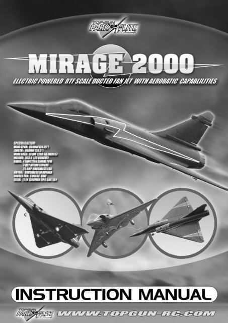
<strong>Mirage</strong> <strong>2000</strong><strong>RTF</strong> <strong>Model</strong>Congratulations on purchasing the <strong>Mirage</strong> <strong>2000</strong> <strong>RTF</strong><strong>INSTRUCTION</strong> <strong>MANUAL</strong>Top Gun Park Flite are proud to present this highperformance ducted fan sport scale model of the<strong>Mirage</strong> <strong>2000</strong> We feel that this model emulates thestyle, performance and character of its full sizecounterpart.Supplied as a Ready to Fly package with transmitter,LiPo flight battery and charger, A<strong>RTF</strong> or Airframeonly, this model has been designed with the utmostcare and attention to detail to produce a lightweight, strong, and realistic looking modelaeroplane with excellent flying characteristics.This model is a high performance miniature aircraftthat allows intermediate to advanced model pilots toperform both scale and aerobatic manoeuvers. Thelight weight, large wing area and delta wing designallow the model to fly both fast and slow, with highspeed rolls and tight turns while maintaining fullcontrol.These instructions assume a reasonable level ofcompetence for both building and flying and werecommend that the model is flown at a recognisedclub with frequency control measures and suitablethird party insurance.2The owner – pilot of this model should take note ofregulations, and local bylaws before flying thisaircraft.Please take time to read through these instructionsbefore commencing assembly. We list operations inorder of works to reduce the risk of damage duringassembly.Please read through the warnings before use.A 11.1V 1300 mAh lithium polymer (LiPo) battery andcharger is included as part of this package andthese cells must be operated with care to preventthe risk of fire.LiPo Batteries are soft cased and can be easilydamaged by sharp items, puncturing of the softcasing can cause fires and we recommend that theyare stored and handled carefully.Use only a LiPo rated charger, set to a maximum of 3cells (11.1v) and no more than 1 amp chargecurrent.Remove battery from the aircraft and charge on anon flammable, non conductive surfaceDue to continual and ongoing product developmentthe parts shown in the manual may differ from thosesupplied.
KIT CONTENTS AND DESCRIPTIONFuselage with ducted fan, motor, ElectronicSpeed Control (ESC) receiver, rudder- steeringservo, pushrods and nose wheel.Two delta wing panels with ailerons connected tofactory installed servosForward stabiliser canards (2 off)Rear fin strake/ ECM Antennae2 Main undercarriage assemblies with wheelsand mounting hardwareSPECIFICATIONSWing span: 680mm (26.75”)Length: 980mm (38.5”)Wing Area: 13 Dm 2 (200 sq inches)Weight: 565 g (20 Ounces)Radio: 4 function 35Mhz PPM3 Qty micro servos25 Amp brushless ESCMotor: Brushless in runner5 blade ducted fan11.1v 1300mAh LiPo battery4 function fully proportional 35Mhz transmitterAdjustable quick release neck strap fortransmitterTube of adhesiveLiPo Battery 3 cell 11.1V 1300 mAh (15c)2- 3 cell balance type 800mAh LiPo charger and12v power lead3
FUSELAGE ASSEMBLY.Supplied complete and ready for use with ductedfan unit using high performance brushless inrunner motor.25Amp Electronic Speed Control (ESC) prewired tomotor with extended leads to forward battery boxand hinged cover.WING ASSEMBLY.Supplied as two halves.Sprung steerable nose wheel assembly.35mhz 8 channel receiver pre-wired to ESC andrudder-steering servo with extension leads to eachwing.Smoked canopyover cockpit withprofile pilot.Nose conesupplied loose.Each wing half includes undercarriage fixing platesand hinged aileron control surfaces.Wing mounted aileron servos connect to controlhorn with pushrods and snap link clevis connector.MAIN UNDERCARRIAGE ASSEMBLIES.Two sets of lightweight wheels fixed onto wiretorque rod undercarriage.Four clamp plates and 8 fixing screws for securingto wing plates.Steerable nose gear is pre fitted to fuselage.Two forward canard surfaces for sides of intakeducts.One Fin strake / ECM antennae for mounting neartop of fin.4
SECTION 2: BATTERY AND CHARGERBATTERY AND CHARGERBATTERY AND CHARGER11.1V (3 cell) 1300mAh (C) LiPo Battery rated at15C max discharge.WARNING:A lithium polymer (LiPo) battery rated at 15C(19.5A) discharge and fast charger is included aspart of this package, these cells must beoperated with care to prevent the risk of fire.LiPo Batteries are soft cased and can be easilydamaged by sharp items, puncturing of the softcasing can cause fires and we recommend thatthey are stored and handled carefully.Use only the supplied balance charger or a LiPorated charger set to a maximum of 3 cells (11.1v)and less than 1 amp charge current.Remove battery from the aircraft and charge on anon flammable, non conductive surfaceThe kit includes a high performance 11.1V (3 cell)12v DC input 0.8 A output balancing type fastcharger for 2 and 3 cell packs.12v crocodile clip connecting leadADHESIVE5ml tube of foam safe adhesive.Note pierce end of tube with pin in screw on lid.1300mAh LiPo Battery rated at 15C (19.5 amp) maxdischarge.This must be charged using the dedicated 12v DCinput 0.8 Amp output fast charger and connectingleadConnect the crocodile lead connectors to a 12V DCpower source (a 12V car battery is ideal), ensuringthat correct polarity is observed. Red is positive (+)and Black is Negative (-).Connect the lead into the matching socket of thebattery charger and the Red LED will illuminate.5
The RIR 4EXA is a fully proportional 4 function35Mhz transmitterThe transmitter is supplied in a Mode 2configuration. Mode 2 is also known as ThrottleLeft.The left stick controls Throttle and ruddermovement.Push the white balance plug of the battery into thematching charger output socket to commencecharging.The green LED illuminates to confirm charging andswitches off when the charge is completeA full charge will take between 1 and 2 hours.The right stick controls aileron and elevatormovement.Battery state is indicated by a bank of colouredLED’s. With green for full and red for empty.As soon as the indicator changes to amber themodel should be landed to allow batteryreplacement.A red LED indicates dangerously low voltage. Themodel should be landed immediately to replacebatteries before all control is lost.Frequency control is by removable crystal, Thetransmitter frequency is identified on the crystalholder located on the front of the transmitter.8 off AA size dry cells or high capacity Nimhbatteries must be inserted before operation.Remove the rear cover and install batteries into thebattery tray as directed by the moulded in polarity(+ & -) markings.TRANSMITTERA small panel of five small slide switches is set onthe front panel of the transmitter.6
Switches 1 to 4 are electronic servo reversingswitches and should be adjusted to give the correctcontrol surface deflections relative to stickmovements.The mix switch activates a ch1-ch2 mix to giveelevon (2 servos both functioning as ailerons andelevators) for delta winged aircraftFor the <strong>Mirage</strong> the switch must be in the ‘Mix’positionSECTION 3: ASSEMBLYLocate the wing halves and fuselage assemblyRemove the protective tape from the wings andfuselage and dry fit the wings and fuselagetogether.Connect the aileron servo leads to the extensionslocated in the fuselage matching black to black andwhite to white.Tuck wires into slot and apply self adhesive tapeover slot.Repeat on opposite wing panelApply adhesive on one wing panel and the matingfuselage. Press into position and use tape or bandsto hold in place.Wipe off any excess adhesive and allow to dry.Locate the main undercarriage assemblies, clampplates and fixing screws.Insert undercarriage into mounting plate and fix inplace with saddles and four self tapping screws.Repeat on opposite wing panelRepeat the procedure to the other wing.Apply adhesive to the remaining wing root andfuselage side. Press wing into position and use tapeor bands to hold in place.Wipe off any excess adhesive and allow to dry.7
SECTION 3: ASSEMBLY CONTINUEDLocate the plastic nose cone and apply a bead ofadhesive to its inside edge.Apply adhesive to the canard and insert into theslot.Be sure to fit canard with its top face sloping down.Push onto the fuselage, wipe off excess adhesiveand allow to dry.Locate the Fin strake / ECM antennae andfuselage.Locate the two plastic forward canards andfuselage.Use a sharp modelling knife to cut a narrow slot inthe side of the fin.Use a sharp modelling knife to cut a narrow slot inthe side of the fuselage behind the air intake.A moulded in line gives the position.A moulded in line gives the position.Apply adhesive to the middle of the Fin strake / ECMantennae and insert into the slot.8
Uncoil the receiver aerial and fully extend to hangoff the rear of the aircraft.Be sure to fit with pointed face forward.Construction is now complete and the followingsteps can be considered as part of the dailyassembly and rigging of the model.SECTION 4: FINAL SET UPOpen the hinged battery bay door by turning thecatches.Check that all controls operate in the correctmanner and that surfaces for elevons (Combinedaileron and elevator) are level.Adjust surfaces if required by unclipping thepushrod clevis connectors and winding in or out tosuit.Insert into the battery and ensure that battery andESC leads project out of the aperture.To adjust the rudder and nose wheel steering it isnecessary to remove the cover plate just behind thecockpit.Loosen the clamp connector before adjusting thepushrod location.WARNING:With the battery connected and the modelswitched on the motor is now live. TheElectronic speed controller (ESC) will go throughits start up procedure and will emit a series ofbeeps while it configures throttle positions. Themotor could start unexpectedly and werecommend that the model is restrained duringhandling.Ensure that transmitter is switched on with throttledown.Connect the battery and ESC leads together Red-redand Black-Black and close the battery cover usingthe catches to lock it in place.With the trims and wheel central re-tighten theclamp connector.Move transmitter sticks to ensure free movement ofthe control surfaces.9
CHECK THE BALANCE.The model should sit level or slightly nose downwhen supported upside down from a point 260 mmfrom the wing trailing edge. This corresponds to apoint midway along the top surface air brakes panelline.Check for adequate range with and without motorrunning.If everything is okay, take it to the flying field andrig it up again.Always follow the frequency control procedures ofyour local flying site and ensure that you haveadequate third party insurance cover.Repeat the full pre flight inspection before flying.WARNING:DO NOT ATTEMPT TO FLY WITH A REARWARDBALANCE POINTDo not advance the throttle unless the model isrestrained. With the powerful motor-fancombination, the model will accelerate across asmooth surface very quickly.CENTRE OF GRAVITY POINT570 mmSECTION 5: FIRST FLIGHTBEFORE THE TEST FLIGHTOn completion of the model take time to test themodel in the workshop.Switch on the transmitter, connect the battery anddouble check that all surfaces operate in the correctmanner without stalled servos.FLYINGThe <strong>Mirage</strong> <strong>2000</strong> is capable of 5 to 10 minute flighttimes and can R.O.G (Rise Off Ground) from smoothmetalled runways. A hand launch will be required Ifflying from grass. It is aerobatic and able toperform loops and rolls.Due to its light weight it should not be flown in windgreater than 10mph.10
Control throws set during assembly will produce amodel capable of flying smooth scale likeperformance and medium to high speed aerobaticmanoeuvers.The control surface movements can be increased bymoving the clevis connectors nearer to the controlsurfaces.To reduce movements move the pushrodconnections nearer to the servo on the output armsand further out along the control surfaces horns.ENJOY YOURSELF BUT ALWAYS FLY SAFE!11
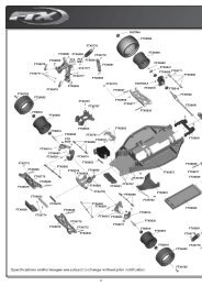
TOP GUN PARKFLITE MIRAGE <strong>2000</strong> SPARE PARTS LISTTGP0180TGP0181TGP0182TGP0183TGP0184TGP0185<strong>Mirage</strong> <strong>2000</strong> EDF EP Fuselage<strong>Mirage</strong> <strong>2000</strong> EDF EP Main Wing Set<strong>Mirage</strong> <strong>2000</strong> EDF EP Nose, Canopy,Plastic Covers<strong>Mirage</strong> <strong>2000</strong> EDF EP Plastic Parts<strong>Mirage</strong> <strong>2000</strong> EDF EP Front Landing Gear<strong>Mirage</strong> <strong>2000</strong> EDF EP Landing GearTGP0186TGP0535TGP0526TGE0001TGE0051<strong>Mirage</strong> <strong>2000</strong> EDF EP Ducted Fanw/o MotorTGPF Outrunner Motor (<strong>Mirage</strong>)TGPF 1300mAh 12c 11.1v Lipo Battery(<strong>Mirage</strong>)Etronix 8.4G Micro ServoEtronix 25A Brushless Speed ControlDISTRIBUTORS OF QUALITY MODEL & HOBBY PRODUCTSSaxon House, Saxon Business Park, Hanbury Road, Bromsgrove, Worcestershire. B60 4AD. EnglandTel: +44 (0) 1527 575349 Fax: + 44 (0) 1527 570536E-mail: info@cmldistribution.co.ukWeb site: www.cmldistribution.co.uk12