Axial Piston Pump Series PV
Axial Piston Pump Series PV
Axial Piston Pump Series PV

You also want an ePaper? Increase the reach of your titles
YUMPU automatically turns print PDFs into web optimized ePapers that Google loves.
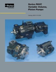
<strong>Axial</strong> <strong>Piston</strong> <strong>Pump</strong><br />
<strong>Series</strong> <strong>PV</strong><br />
Variable Displacement<br />
Catalogue HY11-3243/UK<br />
August 2002
Catalogue HY11-3243/UK<br />
PI <strong>PV</strong>plus UK.PM6.5 RH<br />
2<br />
<strong>Axial</strong> piston pump<br />
<strong>Series</strong> <strong>PV</strong><br />
Note<br />
This document and other information from Parker Hannifin<br />
GmbH, its subsidiaries, sales offices and authorized<br />
distributors provide product or system options for further<br />
investigation by users having technical expertise. Before you<br />
select or use any product or system it is important that you<br />
analyse all aspects of your application and review the<br />
information concerning the product or system in the current<br />
product catalogue. Due to the variety of operating conditions<br />
and applications for these products or systems, the user,<br />
through his own analysis and testing, is solely responsible<br />
for making the final selection of the products and systems<br />
and assuring that all performance and safety requirements<br />
of the application are met. The products are subject to<br />
change by Parker Hannifin GmbH at any time without notice.<br />
Parker Hannifin GmbH<br />
Hydraulic Controls Division<br />
Kaarst, Germany
Catalogue HY11-3243/UK<br />
Table of contents<br />
PI <strong>PV</strong>plus UK.PM6.5 RH<br />
3<br />
<strong>Axial</strong> piston pump<br />
<strong>Series</strong> <strong>PV</strong><br />
Description Page<br />
Introduction 4<br />
Characteristics 5<br />
Ordering code 6<br />
Noise levels 8<br />
Noise reduction measures 9<br />
Efficiency and case drain flows 10<br />
Dimensions<br />
<strong>Pump</strong> combinations<br />
14<br />
Dimensions 26<br />
Thru drive, shaft load limitations<br />
Compensators<br />
28<br />
Dimensions / Seal kit compensators 29<br />
Pressure compensators 30<br />
Load-sensing compensators 31<br />
Horse power compensators 32<br />
Electrohydraulic p/Q control 34<br />
Hydraulic circuit, ordering examples <strong>PV</strong>AP** 36<br />
Hydraulic circuit, ordering examples <strong>PV</strong>AC** 38<br />
Accessories 40<br />
General installation information 41<br />
Parker Hannifin GmbH<br />
Hydraulic Controls Division<br />
Kaarst, Germany
Catalogue HY11-3243/UK<br />
Introduction<br />
PI <strong>PV</strong>plus UK.PM6.5 RH<br />
4<br />
<strong>Axial</strong> piston pump<br />
<strong>Series</strong> <strong>PV</strong><br />
<strong>Pump</strong> with standard pressure compensator code F*S <strong>Pump</strong> with load-sensing compensator code FFC<br />
PM<br />
L P1 A<br />
P L P1 A<br />
S L<br />
With thru drive for single and multiple pumps<br />
Swash plate type for open circuit<br />
Q<br />
= included<br />
p<br />
L P1 A<br />
P L P1 A<br />
<strong>Pump</strong> with horse power compensator code *LB <strong>Pump</strong> with electrohydr. displacement control code *<strong>PV</strong><br />
PM<br />
L P1 A<br />
P L<br />
P1 A<br />
S L<br />
PP<br />
PL<br />
Q<br />
= included<br />
p<br />
PM<br />
S L<br />
Ø0,8<br />
PF<br />
Q<br />
= included<br />
Technical Features<br />
Mounting interface according to VDMA-standards<br />
sheet 24560 part 1<br />
Standard: 4-hole flange ISO 3019/2 (metric). Optional:<br />
4-hole flange ISO 3019/1 (SAE)<br />
Large servo piston with strong bias spring achieves<br />
fast response; e.g. for <strong>PV</strong>046<br />
upstroke < 70 ms ; downstroke < 40 ms<br />
Note: follow installation instructions!<br />
Reduced pressure peaks due to active decompression<br />
of system at downstroke<br />
Also at low system pressure reliable compensator<br />
operation. Lowest compensating pressure
Catalogue HY11-3243/UK<br />
Characteristics<br />
Technical data<br />
Displacement [cm3 Operating pressures<br />
/rev] from 16 to 270<br />
Outlet [bar] nominal pressure p 350 N<br />
[bar] max. pressure p 420 max. 1)<br />
[bar] drain port 2 2)<br />
[bar] Inlet min. 0.8 (absolute)<br />
[bar] max. 16<br />
Minimum speed [min-1 ] 300 min-1 Mounting interface 4-hole flange ISO 3019/2<br />
optional ISO 3019/1, SAE<br />
Installation drain port as high as possible<br />
1) peak pressure only<br />
2) peak pressure only, special version up to 20bar available<br />
<strong>Pump</strong> combinations<br />
See pages 26–27<br />
Selection table<br />
PI <strong>PV</strong>plus UK.PM6.5 RH<br />
5<br />
<strong>Axial</strong> piston pump<br />
<strong>Series</strong> <strong>PV</strong><br />
<strong>Pump</strong> with standard pressure comp. <strong>Pump</strong> with horse power comp.<br />
Combination <strong>PV</strong>/<strong>PV</strong> Combination <strong>PV</strong>/gear pump<br />
Model Max. displacement Output flow Input horse power in kW Max speed 1) Weight<br />
in cm 3 /rev in l/min at 1500 min -1 at 1500 min -1 and 350 bar in min -1 in kg<br />
<strong>PV</strong>016 16 24 15.5<br />
<strong>PV</strong>020 20 30 19.5 3000 19<br />
<strong>PV</strong>023 23 34.5 22.5<br />
<strong>PV</strong>032 32 48 31<br />
<strong>PV</strong>040 40 60 39 2800 30<br />
<strong>PV</strong>046 46 69 45<br />
<strong>PV</strong>063 63 94.5 61.5 2800<br />
<strong>PV</strong>080 80 120 78 2500 60<br />
<strong>PV</strong>092 92 138 89.5 2300<br />
<strong>PV</strong>140 140 210 136 2400 90<br />
<strong>PV</strong>180 180 270 175 2200 90<br />
<strong>PV</strong>270 270 405 263 1800 172<br />
1) The maximum speed ratings are shown for an inlet pressure of 1 bar (absolute) and for a fluid viscosity of ν = 30 mm²/s.<br />
Parker Hannifin GmbH<br />
Hydraulic Controls Division<br />
Kaarst, Germany
Catalogue HY11-3243/UK<br />
Ordering Code<br />
<strong>PV</strong><br />
<strong>Axial</strong> piston<br />
pump<br />
variable<br />
displacement<br />
high<br />
pressure<br />
version<br />
Code Displacement<br />
016 16 cm³/U<br />
020 20 cm³/U<br />
023 23 cm³/U<br />
032 32 cm³/U<br />
040 40 cm³/U<br />
046 46 cm³/U<br />
063 63 cm³/U<br />
080 80 cm³/U<br />
092 92 cm³/U<br />
140 140 cm³/U<br />
180 180 cm³/U<br />
270 270 cm³/U<br />
Code Rotation 1)<br />
R clockwise<br />
L counter clockwise<br />
1) when looked on shaft<br />
Code Variation<br />
1 standard<br />
9 reduced displacement<br />
adjusted 2)<br />
2) for order specify displacement<br />
Code Mounting interface Shaft<br />
D<br />
E<br />
F<br />
4-hole flange<br />
4-hole flange<br />
cylindric, key<br />
splined, SAE<br />
3) G<br />
4-hole flange cylindric, key<br />
3) SAE<br />
ISO<br />
3019/1<br />
4-hole flange splined, SAE<br />
K metr. ISO 4-hole flange cylindric, key<br />
L 3019/2 4-hole flange splined, DIN 5480<br />
3) codes F and G only for <strong>PV</strong>140/180, see dimension sheet<br />
Code Port 4) Threads 5)<br />
1 BSPP metric<br />
3 UNF UNC<br />
4 6) BSPP metr. M14<br />
7 ISO 6149 UNC<br />
8 ISO 6149 metric 1)<br />
PI <strong>PV</strong>plus UK.PM6.5 RH<br />
Size<br />
and<br />
displacement<br />
Rotation<br />
6<br />
<strong>Axial</strong> piston pump<br />
<strong>Series</strong> <strong>PV</strong><br />
pump compensator<br />
Variation Threads 2nd Compensator Design<br />
pump<br />
series:<br />
not required<br />
for order<br />
Mounting<br />
code Thru drive<br />
4) drain, gauge and flushing ports<br />
5) all mounting and connecting threads<br />
6) for <strong>PV</strong>063-<strong>PV</strong>180 only: pressure port 1 1/4" with 4 x M14 instead of 4 x M12<br />
Seals<br />
see opposite page<br />
Code Seals<br />
N NBR<br />
V FPM<br />
E EPR<br />
Code 2nd pump option 7)<br />
single pump, no 2nd pump<br />
1<br />
and coupling<br />
2 <strong>PV</strong>140 or <strong>PV</strong>180 mounted<br />
3 <strong>PV</strong> or <strong>PV</strong>M pump mounted<br />
4 gear pump series PGP mounted<br />
5 PAV/PAF up to 6.3 cm³/rev<br />
mounted<br />
6 PAV10 or PAF8-10 mounted<br />
7) Specify 2nd pump with full model code<br />
Code Thru drive option<br />
no adaptor for 2nd pump<br />
single pump<br />
T<br />
prepared for thru drive<br />
with adaptor for 2nd pump<br />
Y<br />
8) only for <strong>PV</strong>016 - <strong>PV</strong>023<br />
9) only for <strong>PV</strong>032 and larger<br />
10) only for <strong>PV</strong>063 and larger<br />
11) only for <strong>PV</strong>270<br />
12) only for <strong>PV</strong>016 - <strong>PV</strong>092<br />
8) SAE AA, Ø 50.8mm<br />
A SAE A, Ø 82.55mm<br />
B SAE B, Ø 101.6mm<br />
C9) SAE C, Ø 127mm<br />
D10) SAE D, Ø 152.4mm<br />
E11) SAE E, Ø 165.1mm<br />
G12) metric, Ø 63mm<br />
H metric, Ø 80mm<br />
J metric, Ø 100mm<br />
K9) metric, Ø 125mm<br />
L10) metric, Ø 160mm<br />
M11) metric, Ø 200mm<br />
Parker Hannifin GmbH<br />
Hydraulic Controls Division<br />
Kaarst, Germany
Catalogue HY11-3243/UK<br />
Ordering Code<br />
<strong>PV</strong><br />
Code<br />
Standard pressure compensator<br />
Compensator option<br />
0 0 1 No compensator<br />
F D S 10 - 140 bar, spindle + lock nut<br />
F H S 40 - 210 bar, spindle + lock nut<br />
F W S 70 - 350 bar, spindle + lock nut<br />
Remote compensator options<br />
F R Remote pressure compensator<br />
F S Variation R, for quick unload valve<br />
F F Load-Sensing compensator<br />
F T Two valve load-sensing compensator<br />
Variations for remote compensator<br />
C external pressure pilot 13)<br />
1 NG6/D03 interface top side<br />
P Pilot valve <strong>PV</strong>AC1P*M* mounted<br />
D<br />
Proportional pilot valve type<br />
DSAE1007P07KLAF mounted<br />
L Pilot valve with DIN lock mounted<br />
Z Accessory mounted 14)<br />
Horse power compensator<br />
Code Displacement Compensator option<br />
016 032 063<br />
023 046 092<br />
140 180 270<br />
Nom. HP [kW]<br />
at 1500 min<br />
Nom. torque<br />
Function<br />
L x x x x x x Horse power compensator<br />
C x x x x x x<br />
Horse power compensator and<br />
load-sensing<br />
Variation<br />
A x x x x x x NG6 interface top side<br />
B x x x x x x no pressure compensation<br />
-1 [Nm]<br />
B x 3 19.5<br />
C x 4 26<br />
D x x 5.5 36<br />
E x x 7.5 49<br />
G x x x 11 71<br />
H x x x 15 97<br />
K x x x 18.5 120<br />
M x x x x 22 142<br />
S x x x 30 195<br />
T x x x x 37 240<br />
U x x x x 45 290<br />
W x x x 55 355<br />
Y x x 75 485<br />
Z x x 90 585<br />
2 x 110 715<br />
3 x 132 850<br />
C x x x x x x<br />
adjustable<br />
pressure compensation<br />
D x x x x x x Proportional pilot valve<br />
DSAE1007P07KLAF mounted<br />
Z x x x x x x Accessories mounted 2)<br />
PI <strong>PV</strong>plus UK.PM6.5 RH<br />
7<br />
<strong>Axial</strong> piston pump<br />
<strong>Series</strong> <strong>PV</strong><br />
Compensator<br />
13) not for two-valve-compensator<br />
14) Accessories not included,<br />
please specify on order with full<br />
model code.<br />
<strong>Pump</strong> Compensator<br />
Design<br />
series:<br />
not required<br />
for order<br />
Electrohydraulic compensator<br />
Code Compensator option<br />
Pilot pressure supply<br />
F Standard (internal), no shuttle valve<br />
W With shuttle valve, comp. horizontal<br />
Function<br />
P Proportional displacement control<br />
Variation<br />
V Standard, no pressure compensation<br />
Proportional pilot valve<br />
D<br />
DSAE1007P07KLAF mounted<br />
Z Variation R, accessories mounted 14)<br />
R Remote pressure comp. NG6 interface<br />
Variation R, Pressure sensor and<br />
G proportional pilot valve mounted for<br />
pressure resp. horse power control<br />
Remote pressure comp., NG6 interface<br />
S<br />
top side, for quick unload valve<br />
Variation S, pressure sensor and<br />
T proportional pilot valve mounted for<br />
pressure resp. horse power control<br />
Remote pressure comp., NG6 interface top<br />
P side, for preload and quick unload manifold<br />
Variation P, pressure sensor and<br />
E proportional pilot valve mounted for<br />
pressure resp. horse power control<br />
Parker Hannifin GmbH<br />
Hydraulic Controls Division<br />
Kaarst, Germany
Catalogue HY11-3243/UK<br />
Noise levels<br />
<strong>PV</strong>016 - <strong>PV</strong>023 <strong>PV</strong>140<br />
Noise level [dBA]<br />
70<br />
60<br />
50<br />
0 100 200 300<br />
Pressure [bar]<br />
PI <strong>PV</strong>plus UK.PM6.5 RH<br />
at full flow<br />
at deadhead<br />
<strong>PV</strong>032 - <strong>PV</strong>046 <strong>PV</strong>180<br />
Noise level [dBA]<br />
70<br />
60<br />
50<br />
0 100 200 300<br />
Pressure [bar]<br />
<strong>PV</strong>063 - <strong>PV</strong>092<br />
Noise level [dBA]<br />
70<br />
60<br />
at full flow<br />
at full flow<br />
at deadhead<br />
at deadhead<br />
52<br />
0 100 200 300<br />
Pressure [bar]<br />
Typical sound level for single pumps, measured in unechoic chamber<br />
according to DIN 45 635, part 1 and 26. Microphone distance 1m;<br />
speed: n = 1500 min-1.<br />
8<br />
<strong>Axial</strong> piston pump<br />
<strong>Series</strong> <strong>PV</strong><br />
Noise level [dBA]<br />
Noise level [dBA]<br />
<strong>PV</strong>270<br />
Noise level [dBA]<br />
80<br />
70<br />
at full flow<br />
at deadhead<br />
60<br />
0 100 200 300<br />
Pressure [bar]<br />
80<br />
70<br />
at full flow<br />
at deadhead<br />
60<br />
0 100 200 300<br />
Pressure [bar]<br />
80<br />
70<br />
at full flow<br />
at deadhead<br />
60<br />
0 100 200 300<br />
Pressure [bar]<br />
All data measured with mineral oil viscosity 30 mm²/s (cSt) at 50°C.<br />
Parker Hannifin GmbH<br />
Hydraulic Controls Division<br />
Kaarst, Germany
Catalogue HY11-3243/UK<br />
Noise reduction measures<br />
Operating noise of pumps<br />
The normal operating noise of a pump and consequently<br />
the operating noise of the entire hydraulic system is<br />
largely determined by where and how the pump is<br />
mounted and how it is connected to the downstream<br />
hydraulic system.<br />
Also size, style and installation of the hydraulic tubing<br />
have a major influence on the overall noise emitted by a<br />
hydraulic system<br />
Noise reduction measures<br />
Talking about operating noise of a hydraulic pump,<br />
primary and secondary pump noise has to be taken into<br />
consideration<br />
Primary pump noise is caused by vibrations of the<br />
pump body due to internal alternating forces stressing<br />
the body structure.<br />
Flexible elements help to prevent pump body vibration<br />
being transmitted to other construction elements, where<br />
possible amplification may occur. Such elements can be:<br />
Bell housing with elastic dampening flange with<br />
vulcanized labyrinth (1)<br />
Floating and flexible coupling (2)<br />
Damping rails (3) or silent blocks for mounting the<br />
electric motor or the foot mounting flange<br />
Flexible tube connections (compensators) or hoses<br />
on inlet, outlet and drain port of the pump.<br />
Exclusive use of gas tight tube fittings for inlet<br />
connections to avoid ingression of air causing cavitation<br />
and excessive noise.<br />
Secondary pump noise is caused by vibration induced<br />
into all connected hydraulic components by the flow and<br />
pressure pulsation of the pump. This secondary noise<br />
adds typical 7 - 10 dBA to the noise of a pump measured<br />
in the sound chamber according to DIN 45 635 (see<br />
diagrams on opposite side). Therefore pipework, its<br />
mounting and the mounting of all hydraulic components<br />
like pressure filters and control elements has a major<br />
influence to the overall system noise level.<br />
Pulsation reduction with precompression volume:<br />
The <strong>PV</strong> is equipped with a new technology for flow ripple<br />
reduction. This method reduces the pulsation at the pump<br />
outlet by 40 - 60 %. That leads to a significant reduction<br />
of the overall system noise without additional cost and<br />
without additional components (silencers etc.). The typical<br />
reduction reaches 2 - 4 dBA. That means: with a pump<br />
of the <strong>PV</strong> series the secondary noise adds only some 5<br />
- 7 dBA to the pump noise instead of the usually found 7<br />
- 10 dBA.<br />
Figure 2 compares the measured pulsation of a system<br />
with 6 pumps of 180 cm³/rev each.<br />
PI <strong>PV</strong>plus UK.PM6.5 RH<br />
9<br />
<strong>Axial</strong> piston pump<br />
<strong>Series</strong> <strong>PV</strong><br />
Last but not least the connection between pump and<br />
driving motor can be the cause of an unacceptably high<br />
noise emission. Even when the mounting space is limited<br />
there are suitable means and components to reduce the<br />
noise significantly.<br />
The vibration of the pump body, created by high alternating<br />
forces in the rotating group and the pulsation of the<br />
output flow excite every part of the system connected to<br />
the pump mechanically or hydraulically.<br />
1) Bell housing 2) Coupling 3) Damping rails<br />
Figure 1: Components to avoid vibration transfer from<br />
the pump to the drive/installation and their position in the<br />
power unit (numbers refer to the text on the left)<br />
series 20<br />
200<br />
[bar]<br />
180<br />
<strong>PV</strong>180R1K1T1NFWS-series 20<br />
160<br />
<strong>PV</strong>180R1K1T1NFWS-series 40<br />
9.0 9.5 10.0 10.5 11.0 [s]<br />
180<br />
11.5<br />
Parker Hannifin GmbH<br />
Hydraulic Controls Division<br />
Kaarst, Germany<br />
series 40<br />
220<br />
[bar]<br />
Figure 2: Comparison of the pressure pulsation in a<br />
system with 6 old <strong>PV</strong> pumps versus the same system<br />
with 6 <strong>PV</strong>plus pumps. The pulsation reduction effect of<br />
the precompression volume is evident.<br />
Other measures<br />
Small diameter tubes do not only cause high flow speeds,<br />
turbulences inside the tubes and cavitation in the pump,<br />
they also produce noise.<br />
Only correctly sized connections of the largest possible<br />
diameter according to the port size of the pump should be<br />
used.<br />
200
Catalogue HY11-3243/UK<br />
Efficiency and case drain flows<br />
Efficiency, power consumption<br />
<strong>PV</strong>016<br />
Output flow [l/min]<br />
25<br />
20<br />
15<br />
10<br />
5<br />
0<br />
<strong>PV</strong>020<br />
Output flow [l/min]<br />
30<br />
24<br />
18<br />
12<br />
6<br />
0<br />
<strong>PV</strong>023<br />
Output flow [l/min]<br />
40<br />
32<br />
24<br />
16<br />
8<br />
0<br />
Input power [kW]<br />
Input power [kW]<br />
Input power [kW]<br />
20<br />
16<br />
12<br />
8<br />
4<br />
PI <strong>PV</strong>plus UK.PM6.5 RH<br />
output flow<br />
input power at full flow<br />
vol. efficiency<br />
overall e nc<br />
input power at deadhead<br />
ff e<br />
ici y<br />
0<br />
0 100 200 300<br />
Pressure [bar]<br />
25<br />
20<br />
15<br />
10<br />
5<br />
0<br />
0 100 200 300<br />
Pressure [bar]<br />
25<br />
20<br />
15<br />
10<br />
5<br />
output flow, vol. efficiency<br />
vol. efficiency<br />
input power at full flow<br />
overall n<br />
input power at deadhead<br />
output flow<br />
input power at full flow<br />
efficie cy<br />
o e<br />
input power at deadhead<br />
verall effici ncy<br />
0<br />
0 100 200 300<br />
Pressure [bar]<br />
100<br />
80<br />
60<br />
40<br />
20<br />
0<br />
100<br />
80<br />
60<br />
40<br />
20<br />
0<br />
100<br />
80<br />
60<br />
40<br />
20<br />
0<br />
Efficiency [%] (overall, volumetric)<br />
Efficiency [%] (overall, volumetric)<br />
Efficiency [%] (overall, volumetric)<br />
10<br />
<strong>Axial</strong> piston pump<br />
<strong>Series</strong> <strong>PV</strong><br />
Efficiency and case drain flows <strong>PV</strong>016, <strong>PV</strong>020, <strong>PV</strong>023<br />
The efficiency and power graphs are measured at an<br />
input speed of n = 1500 min-1 , a temperature of 50°C and<br />
a fluid viscosity of 30 mm2 /s.<br />
Case drain flow and compensator control flow leave via<br />
the drain port of the pump. To the values shown are to be<br />
added 1 to 1.2 l/min , if at pilot operated compensators<br />
(codes FR*, FF*, FT*, horse power compensator and p/<br />
Q-control) the control flow of the pressure pilot valve also<br />
goes through the pump.<br />
Please note: The values shown below are only valid for<br />
static operation. Under dynamic conditions and at rapid<br />
compensation of the pump the volume displaced by the<br />
servo piston also leaves the case drain port. This dynamic<br />
control flow can reach up to 40 l/min! Therefore the<br />
case drain line is to lead to the reservoir at full size and<br />
without restrictions as short and direct as possible.<br />
Case drain flows <strong>PV</strong>016-023<br />
Case drain flow [l/min]<br />
3<br />
2<br />
1<br />
0<br />
0<br />
at deadhead<br />
100<br />
at full flow<br />
200 300<br />
Pressure [bar]<br />
Parker Hannifin GmbH<br />
Hydraulic Controls Division<br />
Kaarst, Germany
Catalogue HY11-3243/UK<br />
Efficiency and case drain flows<br />
Efficiency, power consumption<br />
<strong>PV</strong>032<br />
Output flow [l/min]<br />
50<br />
40<br />
30<br />
20<br />
10<br />
0<br />
<strong>PV</strong>040<br />
Output flow [l/min]<br />
60<br />
48<br />
36<br />
24<br />
12<br />
0<br />
<strong>PV</strong>046<br />
Output flow [l/min]<br />
80<br />
64<br />
48<br />
32<br />
16<br />
0<br />
Input power [kW]<br />
Input power [kW]<br />
Input power [kW]<br />
40<br />
32<br />
24<br />
16<br />
8<br />
PI <strong>PV</strong>plus UK.PM6.5 RH<br />
output flow<br />
over l<br />
input power at full flow<br />
vol. efficiency<br />
al effici ncy<br />
input power at deadhead<br />
0<br />
0 100 200 300<br />
Pressure [bar]<br />
40<br />
32<br />
24<br />
16<br />
8<br />
0<br />
0 100 200 300<br />
Pressure [bar]<br />
50<br />
40<br />
30<br />
20<br />
10<br />
output flow, vol. efficiency<br />
input power at full flow<br />
e<br />
overall efficiency<br />
input power at deadhead<br />
vol. efficiency<br />
i u<br />
output flow<br />
input power at full flow<br />
overa ffic<br />
np t power at deadhead<br />
ll e iency<br />
0<br />
0 100 200 300<br />
Pressure [bar]<br />
100<br />
80<br />
60<br />
40<br />
20<br />
0<br />
100<br />
80<br />
60<br />
40<br />
20<br />
0<br />
100<br />
80<br />
60<br />
40<br />
20<br />
0<br />
Efficiency [%] (overall, volumetric)<br />
Efficiency [%] (overall, volumetric)<br />
Efficiency [%] (overall, volumetric)<br />
11<br />
<strong>Axial</strong> piston pump<br />
<strong>Series</strong> <strong>PV</strong><br />
Efficiency and case drain flows <strong>PV</strong>032, <strong>PV</strong>040, <strong>PV</strong>046<br />
The efficiency and power graphs are measured at an<br />
input speed of n = 1500 min-1 , a temperature of 50°C and<br />
a fluid viscosity of 30 mm2 /s.<br />
Case drain flow and compensator control flow leave via<br />
the drain port of the pump. To the values shown are to be<br />
added 1 to 1.2 l/min , if at pilot operated compensators<br />
(codes FR*, FF*, FT*, horse power compensator and p-<br />
Q-control) the control flow of the pressure pilot valve also<br />
goes through the pump.<br />
Please note: The values shown below are only valid for<br />
static operation. Under dynamic conditions and at rapid<br />
compensation of the pump the volume displaced by the<br />
servo piston also leaves the case drain port. This dynamic<br />
control flow can reach up to 60 l/min! Therefore the<br />
case drain line is to lead to the reservoir at full size and<br />
without restrictions as short and direct as possible.<br />
Case drain flows <strong>PV</strong>032-046<br />
Case drain flow [l/min]<br />
7.5<br />
5.0<br />
2.5<br />
0<br />
0<br />
at deadhead<br />
100<br />
at full flow<br />
200 300<br />
Pressure [bar]<br />
Parker Hannifin GmbH<br />
Hydraulic Controls Division<br />
Kaarst, Germany
Catalogue HY11-3243/UK<br />
Efficiency and case drain flows<br />
Efficiency, power consumption<br />
<strong>PV</strong>063<br />
Output flow [l/min]<br />
100<br />
80<br />
60<br />
40<br />
20<br />
0<br />
<strong>PV</strong>080<br />
Output flow [l/min]<br />
120<br />
96<br />
72<br />
48<br />
24<br />
0<br />
<strong>PV</strong>092<br />
Output flow [l/min]<br />
150<br />
120<br />
90<br />
60<br />
30<br />
0<br />
Input power [kW]<br />
Input power [kW]<br />
Input power [kW]<br />
70<br />
56<br />
42<br />
28<br />
14<br />
PI <strong>PV</strong>plus UK.PM6.5 RH<br />
output flow<br />
overall efficiency<br />
input power at full flow<br />
vol. efficiency<br />
input power at deadhead<br />
0<br />
0 100 200 300<br />
Pressure [bar]<br />
80<br />
64<br />
48<br />
32<br />
16<br />
0<br />
0 100 200 300<br />
Pressure [bar]<br />
100<br />
80<br />
60<br />
40<br />
20<br />
output flow, vol. efficiency<br />
output flow<br />
overal eff<br />
l iciency<br />
input power at full flow<br />
input power at deadhead<br />
vol. efficiency<br />
overa l<br />
ien y<br />
l effic c<br />
input power at full flow<br />
input power at deadhead<br />
0<br />
0 100 200 300<br />
Pressure [bar]<br />
100<br />
80<br />
60<br />
40<br />
20<br />
0<br />
100<br />
80<br />
60<br />
40<br />
20<br />
0<br />
100<br />
80<br />
60<br />
40<br />
20<br />
Efficiency [%] (overall, volumetric)<br />
Efficiency [%] (overall, volumetric)<br />
0<br />
Efficiency [%] (overall, volumetric)<br />
12<br />
<strong>Axial</strong> piston pump<br />
<strong>Series</strong> <strong>PV</strong><br />
Efficiency and case drain flows <strong>PV</strong>063, <strong>PV</strong>080, <strong>PV</strong>092<br />
The efficiency and power graphs are measured at an<br />
input speed of n = 1500 min-1 , a temperature of 50°C and<br />
a fluid viscosity of 30 mm2 /s.<br />
Case drain flow and compensator control flow leave via<br />
the drain port of the pump. To the values shown are to be<br />
added 1 to 1.2 l/min , if at pilot operated compensators<br />
(codes FR*, FF*, FT*, horse power compensator and p-<br />
Q-control) the control flow of the pressure pilot valve also<br />
goes through the pump.<br />
Please note: The values shown below are only valid for<br />
static operation. Under dynamic conditions and at rapid<br />
compensation of the pump the volume displaced by the<br />
servo piston also leaves the case drain port. This dynamic<br />
control flow can reach up to 80 l/min! Therefore the<br />
case drain line is to lead to the reservoir at full size and<br />
without restrictions as short and direct as possible.<br />
Case drain flows <strong>PV</strong>063-092<br />
Case drain flow [l/min]<br />
9<br />
6<br />
3<br />
0<br />
0<br />
at deadhead<br />
100<br />
at full flow<br />
200 300<br />
Pressure [bar]<br />
Parker Hannifin GmbH<br />
Hydraulic Controls Division<br />
Kaarst, Germany
Catalogue HY11-3243/UK<br />
Efficiency and case drain flows<br />
Efficiency, power consumption<br />
<strong>PV</strong>140<br />
Output flow [l/min]<br />
250<br />
200<br />
150<br />
100<br />
50<br />
0<br />
<strong>PV</strong>180<br />
Output flow [l/min]<br />
Output flow [l/min]<br />
300<br />
240<br />
180<br />
120<br />
60<br />
0<br />
500<br />
400<br />
300<br />
200<br />
100<br />
0<br />
Input power [kW]<br />
Input power [kW]<br />
Input power [kW]<br />
150<br />
120<br />
90<br />
60<br />
30<br />
175<br />
140<br />
105<br />
PI <strong>PV</strong>plus UK.PM6.5 RH<br />
vol. efficiency<br />
overall efficien y<br />
output flow<br />
input power at full flow<br />
input power at deadhead<br />
0<br />
0 100 200 300<br />
Pressure [bar]<br />
70<br />
35<br />
0<br />
0 100 200 300<br />
Pressure [bar]<br />
250<br />
200<br />
150<br />
100<br />
50<br />
vol. efficiency<br />
overall efficiency<br />
output flow<br />
input power at full flow<br />
input power at deadhead<br />
vol. efficiency<br />
overall eff e<br />
ici ncy<br />
output flow<br />
input power at full flow<br />
input power at deadhead<br />
0<br />
0 100 200 300<br />
Pressure [bar]<br />
c<br />
100<br />
80<br />
60<br />
40<br />
20<br />
0<br />
100<br />
80<br />
60<br />
40<br />
20<br />
0<br />
100<br />
80<br />
60<br />
40<br />
20<br />
Efficiency [%] (overall, volumetric)<br />
Efficiency [%] (overall, volumetric)<br />
0<br />
Efficiency [%] (overall, volumetric)<br />
13<br />
<strong>Axial</strong> piston pump<br />
<strong>Series</strong> <strong>PV</strong><br />
Efficiency and case drain flows <strong>PV</strong>140, <strong>PV</strong>180, <strong>PV</strong>270<br />
The efficiency and power graphs are measured at an<br />
input speed of n = 1500 min-1 , a temperature of 50°C and<br />
a fluid viscosity of 30 mm2 /s.<br />
Case drain flow and compensator control flow leave via<br />
the drain port of the pump. To the values shown are to be<br />
added 1 to 1.2 l/min , if at pilot operated compensators<br />
(codes FR*, FF*, FT*, horse power compensator and p-<br />
Q-control) the control flow of the pressure pilot valve also<br />
goes through the pump.<br />
Please note: The values shown below are only valid for<br />
static operation. Under dynamic conditions and at rapid<br />
compensation of the pump the volume displaced by the<br />
servo piston also leaves the case drain port. This dynamic<br />
control flow can reach up to 120 l/min! Therefore<br />
the case drain line is to lead to the reservoir at full size and<br />
without restrictions as short and direct as possible.<br />
Case drain flows <strong>PV</strong>140-180<br />
15<br />
10<br />
5<br />
0<br />
0<br />
at deadhead<br />
<strong>PV</strong>270 Case drain flows <strong>PV</strong>270<br />
Case drain flow [l/min]<br />
Case drain flow [l/min]<br />
18<br />
12<br />
6<br />
0<br />
0<br />
100<br />
at deadhead<br />
100<br />
at full flow<br />
at full flow<br />
200 300<br />
Pressure [bar]<br />
200 300<br />
Pressure [bar]<br />
Parker Hannifin GmbH<br />
Hydraulic Controls Division<br />
Kaarst, Germany
Catalogue HY11-3243/UK<br />
Dimensions<br />
<strong>PV</strong>016 - 023, metric version<br />
55<br />
15<br />
48<br />
X<br />
58.7<br />
PI <strong>PV</strong>plus UK.PM6.5 RH<br />
mounting hole for<br />
horse power compensator pilot<br />
or displacement feedback LVDT<br />
23.8<br />
50.8<br />
30.2<br />
197.5<br />
max. 212<br />
16.5<br />
16.5<br />
drain port L1,<br />
dimensions see L2<br />
127<br />
162<br />
170.5<br />
13<br />
32<br />
gage port M; G1/4<br />
optional M 12 x 1.5; ISO 6149-1<br />
( threads options 7 and 8)<br />
oder 7/16 - 20 UNF<br />
( threads option 3)<br />
Inlet:<br />
flange according ISO 6162<br />
DN 32; PN 250 bar<br />
1 1/4”<br />
32<br />
4 x M10, 18 deep<br />
optional 7/16 - 14 UNC - 2B<br />
( threads options 3 and 7)<br />
4 x M10, 18 deep<br />
optional 3/8 - 16 UNC - 2B<br />
( threads options 3 and 7)<br />
19<br />
Outlet:<br />
flange according ISO 6162<br />
DN 19; PN 400 bar<br />
3/4”<br />
89<br />
9<br />
52<br />
14<br />
<strong>Axial</strong> piston pump<br />
<strong>Series</strong> <strong>PV</strong><br />
drain port L2; G1/2<br />
optional M 22 x 1.5; ISO 6149-1<br />
(threads options 7 and 8)<br />
or 7/8 - 14 UNF<br />
( threads option 3)<br />
140<br />
120<br />
Ø 25k6 Ø 100h8 9<br />
10<br />
80<br />
12<br />
28-0.25 thread M10 - 22 deep<br />
key 8 x 7 x 40<br />
DIN 6885<br />
43<br />
Ø 100 h8<br />
94<br />
132<br />
View X<br />
22<br />
max. 133<br />
Shown with standard pressure compensator<br />
125<br />
flushing port L3; G 3/8<br />
optional M 18 x 1.5; ISO 6149-1<br />
(threads options 7 and 8)<br />
oder 3/4 - 16 UNF<br />
( threads option 3)<br />
The pump shown above has mounting option K<br />
and thru drive option T (prepared for thru drive).<br />
mounting option L<br />
splined shaft W 25 x 1.5 x 15 x 8f DIN 5480<br />
Shown is a clockwise rotating pump. Counter clockwise rotating pumps have inlet, outlet and gauge ports reversed.<br />
Parker Hannifin GmbH<br />
Hydraulic Controls Division<br />
Kaarst, Germany
Catalogue HY11-3243/UK<br />
Dimensions<br />
<strong>PV</strong>016 - 023, SAE version and thru drive<br />
Variation with thru drive<br />
Thru shaft adaptors are available with the following dimensions:<br />
A B C D E F G<br />
63 10 85 - M8 100 M8<br />
80 10 103 - M8 109 M10<br />
100 10.5 125 - M10 - -<br />
50.8 10 - - - 82 M8<br />
82.55 10 - - - 106 M10<br />
101.6 10.5 - 89.8 M12 - -<br />
PI <strong>PV</strong>plus UK.PM6.5 RH<br />
Shown above is mounting option D<br />
197.5<br />
225<br />
Ø 25.4-0.05<br />
28.17±0.13<br />
Ø 101.6-0.05<br />
9.4<br />
8<br />
42<br />
50<br />
46<br />
47.5<br />
Ø 101.6-0.05<br />
15<br />
<strong>Axial</strong> piston pump<br />
<strong>Series</strong> <strong>PV</strong><br />
thread<br />
3/8-16 UNC-2B<br />
22 deep<br />
key<br />
6.35 x 6.35<br />
40 long<br />
44.9<br />
89.8<br />
mounting option E<br />
splined shaft 15T 16/32 DP, flat root, side fit<br />
ANSI B92.1<br />
drive output: splined shaft<br />
13T-16/32 DP, flat root, side fit<br />
ANSI B92.1<br />
B<br />
A<br />
H<br />
G<br />
F<br />
13.5<br />
44.9<br />
89.8<br />
Dimension H and available couplings see page 24.<br />
At threads options 3 and 7 the dimensions E and G are UNC - 2B<br />
threads.<br />
D<br />
C<br />
E<br />
Parker Hannifin GmbH<br />
Hydraulic Controls Division<br />
Kaarst, Germany
Catalogue HY11-3243/UK<br />
Dimensions<br />
<strong>PV</strong>032 - 046, metric version<br />
66 35-0.25 60<br />
17<br />
X<br />
mounting hole for<br />
horse power compensator pilot<br />
or displacement feedback LVDT<br />
69.9<br />
57.2<br />
35.7<br />
27.8<br />
PI <strong>PV</strong>plus UK.PM6.5 RH<br />
38<br />
25<br />
drain port L1,<br />
dimensions see L2<br />
227<br />
max. 245<br />
146<br />
185<br />
197<br />
15<br />
37<br />
gage port M; G1/4<br />
optional M 12 x 1.5; ISO 6149-1<br />
( threads options 7 and 8)<br />
oder 7/16 - 20 UNF<br />
( threads option 3)<br />
Inlet:<br />
flange according ISO 6162<br />
DN 38; PN 200 bar<br />
4 x M12, 18 deep<br />
optional 1/2 - 13 UNC - 2B<br />
( threads options 3 and 7)<br />
4 x M12, 18 deep<br />
optional 7/16 - 14 UNC - 2B<br />
( threads options 3 and 7)<br />
Outlet:<br />
flange according ISO 6162<br />
DN 25; PN 400 bar<br />
drain port L2; G3/4<br />
optional M 27 x 2; ISO 6149-1<br />
(threads options 7 and 8)<br />
or 1 1/16 - 12 UNF<br />
( threads option 3)<br />
9<br />
22<br />
22<br />
98<br />
68<br />
Ø 32k6<br />
47<br />
16<br />
<strong>Axial</strong> piston pump<br />
<strong>Series</strong> <strong>PV</strong><br />
Ø 125h8<br />
9<br />
10<br />
Ø 125 h8<br />
150<br />
153<br />
Thread M10 - 22 deep<br />
Key 10 x 8 x 56<br />
DIN 6885<br />
107<br />
92<br />
The pump shown above has mounting option K<br />
and thru drive option T (prepared for thru drive)<br />
156<br />
View X<br />
28<br />
max. 133<br />
Shown with standard pressure compensator<br />
160<br />
flushing port L3; G 1/2<br />
optional M 22 x 1.5; ISO 6149-1<br />
(threads options 7 and 8)<br />
oder 7/8 - 14 UNF<br />
( threads option 3)<br />
mounting option L<br />
splined shaft W 32 x 1.5 x 20 x 8f DIN 5480<br />
Shown is a clockwise rotating pump. Counter clockwise rotating pumps have inlet, outlet and gauge ports reversed.<br />
14<br />
Parker Hannifin GmbH<br />
Hydraulic Controls Division<br />
Kaarst, Germany
Catalogue HY11-3243/UK<br />
Dimensions<br />
<strong>PV</strong>032 - 046, SAE version and thru drive version<br />
Thru shaft adaptors are available with the following dimensions:<br />
A B C D E F G K L<br />
63 8.5 85 - M8 100 M8 49 261<br />
80 8.5 103 - M8 109 M10 49 261<br />
100 10.5 125 - M10 140 M12 49 261<br />
125 12 160 - M12 - - 49 261<br />
82.55 8 - - - 106 M10 49 261<br />
101.6 11 - 89.8 M12 146 M12 49 261<br />
127 13.5 - 114.5 M12 - - 64 276<br />
PI <strong>PV</strong>plus UK.PM6.5 RH<br />
shown above is mounting option D<br />
Variation with thru drive<br />
227<br />
L<br />
Ø 31.75 -0.05<br />
35.2 ±0.13<br />
12.7<br />
8<br />
60<br />
68<br />
56<br />
K<br />
17<br />
<strong>Axial</strong> piston pump<br />
<strong>Series</strong> <strong>PV</strong><br />
Ø 127 -0.05<br />
Ø 127-0.05<br />
thread<br />
3/8-16 UNC-2B<br />
22 deep<br />
key<br />
7.94 x 7.94<br />
56 long<br />
57.25<br />
114.5<br />
mounting option E<br />
splined shaft 14T 12/24 DP, flat root, side fit<br />
ANSI B92.1<br />
drive output: splined shaft<br />
W 25 x 1.5 x 15 x 8f DIN5480<br />
B<br />
A<br />
H<br />
D<br />
F<br />
Dimension H and available couplings see page 24.<br />
At threads options 3 and 7 the dimensions E and G are UNC - 2B<br />
threads.<br />
C<br />
14<br />
57.25<br />
E<br />
G<br />
114.5<br />
Parker Hannifin GmbH<br />
Hydraulic Controls Division<br />
Kaarst, Germany
Catalogue HY11-3243/UK<br />
Dimensions<br />
<strong>PV</strong>063 - 092, metric version<br />
86<br />
26<br />
X<br />
77.8<br />
66.6<br />
mounting hole for<br />
horse power compensator pilot<br />
or displacement feedback LVDT<br />
42.9<br />
31.8<br />
PI <strong>PV</strong>plus UK.PM6.5 RH<br />
78<br />
287<br />
max. 308<br />
50<br />
238<br />
252<br />
31<br />
31<br />
drain port L1,<br />
dimensions see L2<br />
192<br />
4 x M12, 20 deep<br />
optional 1/2 - 13 UNC - 2B<br />
( threads options 3 and 7)<br />
or threads option 4<br />
( M14, 20 deep)<br />
32<br />
20<br />
43.5<br />
gage port M; G1/4<br />
optional M 12 x 1.5; ISO 6149-1<br />
( threads options 7 and 8)<br />
oder 7/16 - 20 UNF ( threads option 3)<br />
Inlet:<br />
flange according ISO 6162<br />
DN 51; PN 200 bar<br />
4 x M12, 20 deep<br />
optional 1/2 - 13 UNC - 2B<br />
( threads options 3 and 7)<br />
Outlet:<br />
flange according ISO 6162<br />
DN 32; PN 400 bar<br />
drain port L2; G3/4<br />
optional M 27 x 2; ISO 6149-1<br />
(threads options 7 and 8)<br />
or 1 1/16 - 12 UNF<br />
( threads option 3)<br />
121<br />
56<br />
18<br />
<strong>Axial</strong> piston pump<br />
<strong>Series</strong> <strong>PV</strong><br />
Ø 40 k6 Ø 160 h8<br />
9<br />
92<br />
9<br />
10<br />
43 -0.25<br />
196<br />
key 12 x 8 x 80<br />
DIN 6885<br />
Ø 160 h8<br />
181<br />
120<br />
135<br />
thread<br />
M12 - 28 deep<br />
flushing port L3; G 1/2<br />
optional M 22 x 1.5; ISO 6149-1<br />
(threads options 7 and 8)<br />
oder 7/8 - 14 UNF<br />
( threads option 3)<br />
200<br />
View X<br />
36<br />
200<br />
The pump shown above has mounting option K<br />
and thru drive option T (prepared for thru drive).<br />
max. 133<br />
Shown with standard pressure compensator<br />
mounting option L<br />
splined shaft W 40 x 1.5 x 25 x 8f DIN 5480<br />
Shown is a clockwise rotating pump. Counter clockwise rotating pumps have inlet, outlet and gauge ports reversed.<br />
18<br />
Parker Hannifin GmbH<br />
Hydraulic Controls Division<br />
Kaarst, Germany
Catalogue HY11-3243/UK<br />
Dimensions<br />
<strong>PV</strong>063 - 092, SAE version and thru drive version<br />
Thru shaft adaptors are available with the following dimensions:<br />
A B C D E F G K L<br />
63 10 85 - M8 100 M8 58 326<br />
80 10 103 - M8 109 M10 58 326<br />
100 12 125 - M10 140 M12 58 326<br />
125 12 160 - M12 180 M16 58 326<br />
160 12 200 - M16 - - 58 326<br />
82.55 10 - - - 106 M10 58 326<br />
101.6 12 - 89.8 M12 146 M12 58 326<br />
127 14 - 114.5 M12 181 M16 58 326<br />
152.4 14 - 161.6 M16 - - 78 346<br />
PI <strong>PV</strong>plus UK.PM6.5 RH<br />
shown above is mounting option D<br />
Variation with thru drive<br />
287<br />
L<br />
75<br />
key 11.11x11.11<br />
80 long<br />
Ø 44.45 -0.05<br />
12.7<br />
8<br />
82<br />
90<br />
49.3 ±0.13<br />
Ø 152.4 -0.05<br />
19<br />
<strong>Axial</strong> piston pump<br />
<strong>Series</strong> <strong>PV</strong><br />
Ø 152.4 -0.05<br />
thread<br />
1/2-13 UNC-2B<br />
28 deep<br />
80.8<br />
161.6<br />
mounting option E<br />
splined shaft 13T 8/16 DP, flat root, side fit<br />
ANSI B92.1<br />
drive output: splined shaft<br />
W 32 x 1.5 x 20 x 8f DIN5480<br />
K<br />
B<br />
H<br />
A<br />
D<br />
F<br />
C<br />
20.6<br />
161.6<br />
80.8<br />
Dimension H and available couplings see page 24.<br />
At threads options 3 and 7 the dimensions E and G are UNC - 2B<br />
threads.<br />
Parker Hannifin GmbH<br />
Hydraulic Controls Division<br />
Kaarst, Germany<br />
E<br />
G
Catalogue HY11-3243/UK<br />
Dimensions<br />
<strong>PV</strong>0140 - 180, metric version<br />
106<br />
X<br />
88.9<br />
66.6<br />
31.8<br />
PI <strong>PV</strong>plus UK.PM6.5 RH<br />
mounting hole for<br />
horse power compensator<br />
pilot or LVDT for<br />
displacement feedback<br />
50.8<br />
max. 385<br />
105<br />
gage port M; G1/4<br />
optional M 12 x 1.5; ISO 6149-1<br />
( threads options 7 and 8)<br />
oder 7/16 - 20 UNF<br />
( threads option 3)<br />
283<br />
35<br />
35<br />
drain port L1<br />
dimensions see L2<br />
350<br />
233<br />
pressure port: 295<br />
suction port: 305<br />
Inlet:<br />
flange according ISO 6162<br />
DN 64; PN 160 bar<br />
4 x M12, 20 deep<br />
optional 1/2 - 13 UNC - 2B<br />
( threads options 3 and 7)<br />
or threads option 4<br />
( M14, 22 deep)<br />
32<br />
Outlet:<br />
flange according ISO 6162<br />
DN 32; PN 400 bar<br />
78<br />
20<br />
<strong>Axial</strong> piston pump<br />
<strong>Series</strong> <strong>PV</strong><br />
drain port L2; G1<br />
optional M 33 x 2; ISO 6149-1<br />
(threads options 7 and 8)<br />
or 1 5/16 - 12 UNF<br />
( threads option 3)<br />
20<br />
48<br />
53.5-0.25<br />
The pump shown above has mounting option K<br />
64<br />
and thru drive option T (prepared for thru drive).<br />
4 x M12, 20 deep<br />
optional 1/2 - 13 UNC - 2B<br />
( threads options 3 and 7)<br />
147<br />
Ø 50k6<br />
Ø 160h8<br />
9<br />
92<br />
Ø 160 h8<br />
200<br />
9<br />
10<br />
Key 14 x 9 x 75<br />
DIN 6885<br />
204<br />
158<br />
145<br />
Thread M16 - 36 deep<br />
200<br />
View X<br />
200<br />
40<br />
max. 133<br />
Shown with standard pressure compensator<br />
flushing port L3; G 3/4<br />
optional M 27 x 2; ISO 6149-1<br />
(threads options 7 and 8)<br />
oder 1 1/16 - 12 UNF<br />
( threads option 3)<br />
mounting option L<br />
splined shaft W 50 x 2 x 24 x 9g DIN 5480<br />
Shown is a clockwise rotating pump. Counter clockwise rotating pumps have inlet, outlet and gauge ports reversed.<br />
18<br />
Parker Hannifin GmbH<br />
Hydraulic Controls Division<br />
Kaarst, Germany
Catalogue HY11-3243/UK<br />
Dimensions<br />
<strong>PV</strong>140 - 180, SAE version and thru drive version<br />
Variation with thru drive<br />
Thru shaft adaptors are available with the following dimensions:<br />
A B C D E F G<br />
80 10 103 - M8 109 M10<br />
100 12 125 - M10 140 M12<br />
125 12 160 - M12 180 M16<br />
160 12 200 - M16 - -<br />
82.55 10 - - - 106 M10<br />
101.6 12 - 89.8 M12 146 M12<br />
127 14 - 114.5 M12 181 M16<br />
152.4 14 - 161.6 M16 - -<br />
PI <strong>PV</strong>plus UK.PM6.5 RH<br />
shown above is mounting option D<br />
88<br />
Ø 152.4-0.05<br />
mounting option E<br />
splined shaft 15T 8/16 DP,<br />
flat root, side fit<br />
ANSI B92.1<br />
415<br />
350<br />
21<br />
<strong>Axial</strong> piston pump<br />
<strong>Series</strong> <strong>PV</strong><br />
Ø 50.8-0.05<br />
56.4±0.13<br />
12.7<br />
8<br />
91.4<br />
99.4<br />
Ø 152.4 -0.05<br />
thread<br />
5/8-11UNC-2B<br />
25 deep<br />
key 12.7 x 12.7<br />
75 long<br />
mounting option F<br />
Ø 44.45-0.05 key<br />
49.3±0.13 11.11 x 11.11<br />
55 long<br />
Ø 152.4-0.05<br />
thread<br />
1/2-13UNC-2B<br />
25 deep<br />
75 75<br />
drive output: splined shaft<br />
W 40 x 1.5 x 25 x 8f DIN5480<br />
97<br />
B<br />
A<br />
H<br />
80.8<br />
161.6<br />
Ø 152.4-0.05<br />
21<br />
80.8<br />
161.6<br />
mounting option G<br />
splined shaft 13T 8/16 DP,<br />
flat root, side fit<br />
ANSI B92.1<br />
F<br />
Dimension H and available couplings see page 24.<br />
At threads options 3 and 7 the dimensions E and G are UNC - 2B<br />
threads.<br />
D<br />
C<br />
Parker Hannifin GmbH<br />
Hydraulic Controls Division<br />
Kaarst, Germany<br />
E<br />
G
Catalogue HY11-3243/UK<br />
Dimensions<br />
<strong>PV</strong> 270, metric version<br />
128<br />
110<br />
X<br />
120.7<br />
79.4<br />
PI <strong>PV</strong>plus UK.PM6.5 RH<br />
mounting hole for<br />
horse power pilot<br />
or LVDT for<br />
displacement feedback<br />
69.8<br />
36.5<br />
472.5<br />
max. 510<br />
Ø 88<br />
Ø 38<br />
403<br />
378<br />
306<br />
45<br />
45<br />
drain port L1, dimensions see L2<br />
25<br />
60<br />
22<br />
<strong>Axial</strong> piston pump<br />
<strong>Series</strong> <strong>PV</strong><br />
drain port L2; G1 1/4<br />
optional M 42 x 2; ISO 6149-1<br />
(threads options 7 and 8)<br />
or 1 5/8 - 12 UNF<br />
threads option 3)<br />
Ø 65 k6<br />
9<br />
115<br />
gage port M; G1/4<br />
optional M 12 x 1.5; ISO 6149-1 ( threads options 7 and 8)<br />
or 7/16 - 20 UNF ( threads option 3)<br />
Inlet:<br />
flange according ISO 6162<br />
DN 89; PN 25 bar<br />
4 x M16, 32 deepf<br />
optional 5/8 - 11 UNC - 2B<br />
( threads options 3 and 7)<br />
4 x M16, 32 deep<br />
optional 5/8 - 11 UNC - 2B<br />
threads options 3 and 7)<br />
Outlet:<br />
flange according ISO 6162<br />
DN 38; PN 400 bar<br />
172<br />
80<br />
69 -0.25<br />
Ø 200 h8<br />
Ø 200 h8<br />
9<br />
10<br />
230<br />
184<br />
176<br />
shown with standard<br />
pressure compensator<br />
key 18 x 11 x 98<br />
DIN 6885<br />
22<br />
thread<br />
M20 - 42 deep<br />
265<br />
max. 133<br />
The pump shown above has mounting option K<br />
and thru drive variation T (prepared for thru drive).<br />
250<br />
view X<br />
50<br />
250<br />
flushing port L3; G 3/4<br />
optional M 27 x 2; ISO 6149-1<br />
( threads options 7 and 8)<br />
or 1 1/16 - 12 UNF<br />
( threads option 3)<br />
mounting option L<br />
splined shaft W 60 x 2 x 28 x 9g DIN 5480<br />
Shown is a clockwise rotating pump. Counter clockwise rotating pumps have inlet, outlet and gauge ports reversed.<br />
Parker Hannifin GmbH<br />
Hydraulic Controls Division<br />
Kaarst, Germany
Catalogue HY11-3243/UK<br />
Dimensions<br />
<strong>PV</strong> 270, SAE version and thru drive version<br />
Variation with thru drive<br />
Thru shaft adaptors are available with the following dimensions:<br />
A B C D E F G<br />
80 8.5 103 - M8 109 M10<br />
100 10.5 125 - M10 140 M12<br />
125 10.5 160 - M12 180 M16<br />
160 13.5 200 - M16 224 M20<br />
200 13.5 250 - M20 - -<br />
82.55 8 - - - 106 M10<br />
101.6 11 - 89.8 M12 146 M12<br />
127 13.5 - 114.5 M12 181 M16<br />
152.4 13.5 - 161.6 M16 229 M20<br />
165.1 17 - 224.5 M20 - -<br />
PI <strong>PV</strong>plus UK.PM6.5 RH<br />
shown above is mounting option D<br />
472.5<br />
531.5<br />
88<br />
23<br />
<strong>Axial</strong> piston pump<br />
<strong>Series</strong> <strong>PV</strong><br />
key<br />
12.7 x 12.7<br />
75 long<br />
Ø 50.8 -0.05<br />
56.4 ±0.13<br />
15.9<br />
8<br />
89.5<br />
97.5<br />
Ø 165.1 -0.05<br />
Ø 165.1 -0.05<br />
thread<br />
5/8-11UNC-2B<br />
25 deep<br />
112.25<br />
224.5<br />
mounting option E<br />
splined shaft 15T-8/16 DP, flat root, side fit<br />
ANSI B92.1<br />
output: splined shaft<br />
W 50 x 2 x 24 x 9g DIN 5480<br />
97<br />
B<br />
H<br />
A<br />
D F<br />
20.6<br />
224.5<br />
112.25<br />
Dimension H and available couplings see page 24.<br />
At threads options 3 and 7 the dimensions E and G are UNC - 2B<br />
threads.<br />
C<br />
Parker Hannifin GmbH<br />
Hydraulic Controls Division<br />
Kaarst, Germany<br />
E<br />
G
Catalogue HY11-3243/UK<br />
Kits<br />
Mounting kits for multiple pumps, for second pump option<br />
69<br />
PI <strong>PV</strong>plus UK.PM6.5 RH<br />
MK<br />
<strong>PV</strong><br />
Mounting <strong>Axial</strong><br />
kit piston<br />
pump<br />
series <strong>PV</strong><br />
Code <strong>Pump</strong> size<br />
1 <strong>Pump</strong> size 1: <strong>PV</strong>016 - <strong>PV</strong>023<br />
2 <strong>Pump</strong> size 2: <strong>PV</strong>032 - <strong>PV</strong>046<br />
3 <strong>Pump</strong> size 3: <strong>PV</strong>063 - <strong>PV</strong>092<br />
4 <strong>Pump</strong> size 4: <strong>PV</strong>140 - <strong>PV</strong>180<br />
5 <strong>Pump</strong> size 5: <strong>PV</strong>270<br />
Kit contains positions 30, 69, 84,<br />
85 and 87, see drawing below.<br />
85 87<br />
BG<br />
Mounting kits for multiple pumps, couplings<br />
Code <strong>Pump</strong> size<br />
1 <strong>Pump</strong> size 1: <strong>PV</strong>016 - <strong>PV</strong>023<br />
2 <strong>Pump</strong> size 2: <strong>PV</strong>032 - <strong>PV</strong>046<br />
3 <strong>Pump</strong> size 3: <strong>PV</strong>063 - <strong>PV</strong>092<br />
4 <strong>Pump</strong> size 4: <strong>PV</strong>140 - <strong>PV</strong>180<br />
5 <strong>Pump</strong> size 5: <strong>PV</strong>270<br />
Kit contains positions 91 (and 92 for<br />
keyed shaft).<br />
MK<br />
<strong>PV</strong><br />
Mounting <strong>Axial</strong><br />
kit piston<br />
pump<br />
series <strong>PV</strong><br />
Size<br />
BG<br />
24<br />
<strong>Axial</strong> piston pump<br />
<strong>Series</strong> <strong>PV</strong><br />
Second<br />
pump<br />
front pump 30 84 91<br />
second pump<br />
92<br />
Size<br />
SAE,<br />
splined<br />
Thread<br />
Code Second pump, SAE<br />
Y SAE AA, diameter 50.8 mm<br />
A SAE A, diameter 82.55 mm<br />
B SAE B, diameter 101.6 mm<br />
C SAE C, diameter 127,mm<br />
D SAE D, diameter 152.4 mm<br />
E SAE E, diameter 165.1 mm<br />
Second pump, metric<br />
G Diameter 63 mm<br />
H Diameter 80 mm<br />
J Diameter 100 mm<br />
K Diameter 125 mm<br />
L Diameter 160 mm<br />
M Diameter 200 mm<br />
Coupling<br />
keyed shaft,<br />
(only up to Ø 18,<br />
metric)<br />
metric,<br />
splined<br />
Seals<br />
Design<br />
series<br />
(see name<br />
plate)<br />
Design<br />
series<br />
(see name<br />
plate)<br />
Code Seals<br />
N NBR<br />
V FPM<br />
E EPR<br />
Code Thread<br />
M metric<br />
S SAE<br />
Code Coupling for metric,<br />
splined shaft DIN 5480<br />
01 N25 x 1.5 x 15<br />
02 N32 x 1.5 x 20<br />
03 N40 x 1.5 x 25<br />
04 N50 x 2 x 24<br />
05 N60 x 2 x 28<br />
Coupling for SAE splined shaft<br />
flat root, side fit<br />
11 9T 16/32<br />
12 11T 16/32<br />
13 13T 16/32<br />
14 15T 16/32<br />
15 14T 12/24<br />
16 17T 12/24<br />
17 13T 8/16<br />
18 15T 8/16<br />
Coupling + adaptor<br />
for keyed shaft<br />
20 Diameter 12 mm<br />
21 Diameter 16 mm<br />
22 Diameter 18 mm<br />
Parker Hannifin GmbH<br />
Hydraulic Controls Division<br />
Kaarst, Germany
Catalogue HY11-3243/UK<br />
Kits<br />
Seal kits<br />
Code Displacement<br />
016 <strong>PV</strong>016 063 <strong>PV</strong>063<br />
020 <strong>PV</strong>020 080 <strong>PV</strong>080<br />
023 <strong>PV</strong>023 092 <strong>PV</strong>092<br />
032 <strong>PV</strong>032 140 <strong>PV</strong>140<br />
040 <strong>PV</strong>040 180 <strong>PV</strong>180<br />
046 <strong>PV</strong>046 270 <strong>PV</strong>270<br />
PI <strong>PV</strong>plus UK.PM6.5 RH<br />
SK <strong>PV</strong> BG<br />
Seal kit<br />
Code <strong>Pump</strong> size<br />
1 <strong>Pump</strong> size 1: <strong>PV</strong>016 - <strong>PV</strong>023<br />
2 <strong>Pump</strong> size 2: <strong>PV</strong>032 - <strong>PV</strong>046<br />
3 <strong>Pump</strong> size 3: <strong>PV</strong>063 - <strong>PV</strong>092<br />
4 <strong>Pump</strong> size 4: <strong>PV</strong>140 - <strong>PV</strong>180<br />
5 <strong>Pump</strong> size 5: <strong>PV</strong>270<br />
Repair and spare parts kits<br />
Spare<br />
parts kit<br />
Code <strong>Pump</strong> Size<br />
1 <strong>Pump</strong> size 1: <strong>PV</strong>016 - <strong>PV</strong>023<br />
2 <strong>Pump</strong> size 2: <strong>PV</strong>032 - <strong>PV</strong>046<br />
3 <strong>Pump</strong> size 3: <strong>PV</strong>063 - <strong>PV</strong>092<br />
4 <strong>Pump</strong> size 4: <strong>PV</strong>140 - <strong>PV</strong>180<br />
5 <strong>Pump</strong> size 5: <strong>PV</strong>270<br />
<strong>Axial</strong><br />
piston<br />
pump<br />
series<br />
<strong>PV</strong><br />
RK <strong>PV</strong> BG<br />
<strong>Axial</strong><br />
piston<br />
pump<br />
series<br />
<strong>PV</strong><br />
RK<br />
<strong>PV</strong><br />
Spare <strong>Axial</strong><br />
parts kit piston<br />
pump<br />
series <strong>PV</strong><br />
Size<br />
Code Contents<br />
HE Displacement limiter<br />
adjustable<br />
25<br />
<strong>Axial</strong> piston pump<br />
<strong>Series</strong> <strong>PV</strong><br />
Seals<br />
Code Seals<br />
N NBR<br />
V FPM<br />
E EPR<br />
Thread,<br />
port<br />
Size Contents partly<br />
optional:Thread<br />
or rotation or<br />
seals<br />
Repair and spare parts kits for adjustable displacement limiter<br />
Displacement<br />
Contents Seals<br />
Design<br />
series<br />
(see name<br />
plate)<br />
Code Thread Port<br />
1 metric BSPP<br />
3 UNC UNF<br />
7 UNC ISO 6149<br />
8 metric ISO 6149<br />
Design<br />
series<br />
(see name<br />
plate)<br />
Code Contents Optional<br />
VT Connecting parts, kit Thread<br />
WP Shaft with key Thread<br />
WZ Splined shaft Thread<br />
SS Valve plate Rotation<br />
SB Bushing for servo piston<br />
Contents - fixed<br />
Seals<br />
GLE Trunnion bearing kit<br />
ROG Rotating unit incl. piston set<br />
KOS <strong>Piston</strong> set<br />
SRS Swash plate<br />
WQS Shaft with key, reinforced, only for size 4, only with SAE<br />
WFS Splined shaft, reinforced, only for size 4, only with SAE<br />
RFE Bias spring kit<br />
SKS Servo piston kit<br />
Design<br />
series<br />
(see name<br />
plate)<br />
Code Thread<br />
M metric<br />
S SAE / UNC<br />
Rotation<br />
R clockwise<br />
L counter-clockw.<br />
Seals<br />
N NBR<br />
V FPM<br />
E EPR<br />
Code Seals<br />
N NBR<br />
V FPM<br />
E EPR<br />
For parts included, see spare parts list <strong>PV</strong>I-BGx-GB-yy; available upon request.<br />
x stands for frame size 1 - 5<br />
yy stands for design series<br />
Parker Hannifin GmbH<br />
Hydraulic Controls Division<br />
Kaarst, Germany
Catalogue HY11-3243/UK<br />
<strong>Pump</strong> Combinations<br />
Combinations <strong>PV</strong>/<strong>PV</strong>, <strong>PV</strong>/<strong>PV</strong>M (metric version)<br />
PI <strong>PV</strong>plus UK.PM6.5 RH<br />
M K<br />
L<br />
D C<br />
26<br />
<strong>Axial</strong> piston pump<br />
<strong>Series</strong> <strong>PV</strong><br />
Main pump Second pump Interface main pump L B C D H K M<br />
<strong>PV</strong>016, 020 or 023<br />
<strong>PV</strong>016, 020 or 023<br />
<strong>PV</strong>032, 040 or 046<br />
<strong>PV</strong>016, 020 or 023<br />
<strong>PV</strong>032, 040 or 046<br />
<strong>PV</strong>063, 080 or 092<br />
<strong>PV</strong>016, 020 or 023<br />
<strong>PV</strong>032, 040 or 046<br />
<strong>PV</strong>063, 080 or 092<br />
<strong>PV</strong>140 or 1801) <strong>PV</strong>016, 020 or 023<br />
<strong>PV</strong>032, 040 or 046<br />
<strong>PV</strong>063, 080 or 092<br />
<strong>PV</strong>140 or 180<br />
<strong>PV</strong>2701) <strong>PV</strong>016, 020 or 023<br />
100 B4 HW 489 196 170.5 225 220 225 212<br />
<strong>PV</strong>032, 040 or 046<br />
125 B4 HW<br />
541<br />
574<br />
208<br />
208<br />
197<br />
197<br />
235.5<br />
261<br />
245<br />
245<br />
261<br />
261<br />
212<br />
245<br />
630 232 252 244.5 299 326 212<br />
<strong>PV</strong>063, 080 or 092<br />
160 B4 HW 663 232 252 271 299 326 245<br />
724 232 252 326 299 326 306<br />
719 230 305 280.5 349 415 212<br />
<strong>PV</strong>140 or 180<br />
160 B4 HW<br />
752<br />
813<br />
230<br />
230<br />
305<br />
305<br />
307<br />
362<br />
349<br />
349<br />
415<br />
415<br />
245<br />
306<br />
878 230 305 415 349 415 385<br />
860 255 403 299 406 531.5 212<br />
<strong>PV</strong>270<br />
200 B4 HW<br />
893<br />
954<br />
255<br />
255<br />
403<br />
403<br />
325.5<br />
380.5<br />
406<br />
406<br />
531.5<br />
531.5<br />
245<br />
306<br />
1033 255 403 433.5 406 531.5 385<br />
1134 255 403 531.5 406 531.5 510<br />
1) Combinations <strong>PV</strong>140/180 + <strong>PV</strong>140/180 and <strong>PV</strong>270 + <strong>PV</strong>270 only with splined shaft on main pump due to high torque.<br />
H<br />
B<br />
Parker Hannifin GmbH<br />
Hydraulic Controls Division<br />
Kaarst, Germany
Catalogue HY11-3243/UK<br />
<strong>Pump</strong> Combinations<br />
Combinations <strong>PV</strong>/PGP<br />
<strong>PV</strong>016, 020 or 023 PGP511 100 B4 HW 420<br />
<strong>PV</strong>032, 040 or 046<br />
PGP511<br />
PGP517<br />
125 B4 HW<br />
472<br />
506<br />
<strong>PV</strong>063, 080 or 092<br />
PGP511<br />
PGP517<br />
160 B4 HW<br />
561<br />
595<br />
<strong>PV</strong>140 or 180<br />
PGP511<br />
PGP517<br />
160 B4 HW<br />
650<br />
684<br />
<strong>PV</strong>270<br />
PGP511<br />
PGP517<br />
200 B4 HW<br />
790.5<br />
824.5<br />
* maximum length with largest displacement of a gear pump frame size<br />
PI <strong>PV</strong>plus UK.PM6.5 RH<br />
M<br />
L<br />
K<br />
D C<br />
27<br />
<strong>Axial</strong> piston pump<br />
<strong>Series</strong> <strong>PV</strong><br />
Main pump Second pump Interface main pump L* B C D* H K M<br />
Standard gear pumps for combination with <strong>PV</strong><br />
Model Ordering code<br />
PGP505<br />
PGP511<br />
H<br />
196<br />
208<br />
208<br />
232<br />
232<br />
230<br />
230<br />
255<br />
255<br />
170.5<br />
197<br />
197<br />
252<br />
252<br />
305<br />
305<br />
403<br />
403<br />
124<br />
133.5<br />
152<br />
143.5<br />
162<br />
179.5<br />
198<br />
198<br />
216.5<br />
B<br />
220<br />
245<br />
245<br />
301<br />
301<br />
349<br />
349<br />
406<br />
406<br />
225<br />
261<br />
261<br />
326<br />
326<br />
415<br />
415<br />
531.5<br />
531.5<br />
Displacement Flow<br />
[cm 3 /U] [l/min at 1500min -1 ]<br />
PGP505A0040CA1H2NJ4J4B1B1 4 6<br />
PGP505A0080CA1H2NJ4J4B1B1 8 12<br />
PGP511A0110CA1H2NL2L1B1B1 11 16.5<br />
PGP511A0140CA1H2NL2L1B1B1 14 21<br />
PGP511A0190CA1H2NL2L1B1B1 19 28.5<br />
PGP511A0220CA1H2NL2L2B1B1 22 33<br />
PGP511A0270CA1H2NL2L2B1B1 27 40.5<br />
PGP511A0330CA1H2NL2L2B1B1 33 49.5<br />
PGP517A0230CD1H3NL3L2B1B1 23 34.5<br />
PGP517A0280CD1H3NL3L2B1B1 28 42<br />
PGP517<br />
PGP517A0330CD1H3NL3L2B1B1<br />
PGP517A0380CD1H3NL3L2B1B1<br />
33<br />
38<br />
49.5<br />
57<br />
PGP517A0520CD1H3NL3L3B1B1 52 78<br />
PGP517A0700CD1H3NL3L3B1B1 70 105<br />
PGP350 PGP350A197EVAB2025 83.6 125.4<br />
For technical information see gearpump /-motor catalogue (on request: HY11-3252/UK)<br />
Parker Hannifin GmbH<br />
Hydraulic Controls Division<br />
Kaarst, Germany<br />
99 -143<br />
99 -143<br />
132 -177<br />
99 -143<br />
132 -177<br />
99 -143<br />
132 -177<br />
99 -143<br />
132 -177
Catalogue HY11-3243/UK<br />
Thru drive, shaft load limitations<br />
Max. transferable torque in [Nm] for different shafts options<br />
PI <strong>PV</strong>plus UK.PM6.5 RH<br />
28<br />
<strong>Axial</strong> piston pump<br />
<strong>Series</strong> <strong>PV</strong><br />
Shaft Code<br />
<strong>PV</strong>016-023 <strong>PV</strong>032-046 <strong>PV</strong>063-092 <strong>PV</strong>140-180 <strong>PV</strong>270<br />
D 300 550 1320 2000 2000<br />
E 300 610 1218 2680 2680<br />
F -- -- -- 1320 --<br />
G -- -- -- 1640 --<br />
K 300 570 1150 1900 2850<br />
L 405 675 1400 2650 3980<br />
Max. torque transmission<br />
cap. for rear mount. pumps<br />
140 275 560 1100 1650<br />
Important notice<br />
The max. allowable torque of the individual shaft must<br />
not be exceeded. For 2-pump combinations there is no<br />
problem because <strong>PV</strong> series offers 100% thru torque. For<br />
3-pump combinations (and more) the limit torque could<br />
be reached or exceeded.<br />
Therefore it is necessary to calculate the torque factor<br />
and compare it with the allowed torque limit factor in the<br />
table.<br />
Required: calculated torque factor<br />
< torque limit factor<br />
To make the necessary calculations easier and more user<br />
friendly it is not required to calculate actual torque requirements<br />
in Nm and compare them with the shaft limitations.<br />
The table on the right shows limit factors that include<br />
material specification, safety factors and conversion<br />
factors.<br />
The total torque factor is represented by the sum of the<br />
individual torque factors of all pumps in the complete pump<br />
combination.<br />
Total torque factor of the combination<br />
= sum of individual torque factors of all pumps<br />
The torque factor of each individual pump is calculated<br />
by multiplying the max. operating pressure p of the pump<br />
(in bar) with the max. displacement Vg of the pump (in<br />
cm³/rev).<br />
Torque factor of any pump<br />
= p x Vg<br />
<strong>Pump</strong> Shaft Torque limit factor<br />
D 17700<br />
<strong>PV</strong>016-023<br />
E<br />
K<br />
17700<br />
17700<br />
L 20130<br />
D 32680<br />
<strong>PV</strong>032-046<br />
E<br />
K<br />
36380<br />
33810<br />
L 40250<br />
D 77280<br />
<strong>PV</strong>063-092<br />
E<br />
K<br />
72450<br />
67620<br />
L 83720<br />
D 118400<br />
E 158760<br />
<strong>PV</strong>140-180<br />
F<br />
G<br />
78750<br />
97650<br />
K 113400<br />
L 157500<br />
D 119000<br />
<strong>PV</strong>270<br />
E<br />
K<br />
159700<br />
170100<br />
L 236250<br />
Parker Hannifin GmbH<br />
Hydraulic Controls Division<br />
Kaarst, Germany
Catalogue HY11-3243/UK<br />
Compensators dimensions<br />
Remote pressure compensator, code FRC<br />
Load sensing compensator, code FFC<br />
All control ports G1/4 optional M 12 x 1.5; ISO 6149-1<br />
(threads options 7 and 8) or 7/16-20 UNF (threads option 3)<br />
74.5<br />
pressure pilot port P P (code FRC)<br />
load-sensing-port<br />
P F (code FFC)<br />
2-valve compensator, code FT1<br />
80<br />
Seal kit, compensator<br />
PI <strong>PV</strong>plus UK.PM6.5 RH<br />
T<br />
P<br />
interface NG6, CETOP 03<br />
load sensing port P F<br />
42.5<br />
24<br />
29<br />
<strong>Axial</strong> piston pump<br />
<strong>Series</strong> <strong>PV</strong><br />
Remote pressure comp. with interface NG6, code FR1<br />
Load sensing comp. with interface NG6, code FF1<br />
Proportional p-Q-compensator, code FPR (for code<br />
F<strong>PV</strong> lower valve only without interface)<br />
LVDT for proportional compensator Pilot valve for horse power compensator<br />
round connector<br />
M 12 x 1<br />
5 pins<br />
pump body<br />
SK <strong>PV</strong>C<br />
Seal kit<br />
Compensator<br />
for axial<br />
piston pump<br />
series <strong>PV</strong><br />
69<br />
Seal<br />
40<br />
Code Seal<br />
N NBR<br />
V FPM<br />
E EPR<br />
50<br />
40<br />
2 x M5 - 10 deep optional 10-32 UNC<br />
(threads option 3 and 7)<br />
31<br />
31.5<br />
T<br />
P<br />
32,5<br />
load-sensing-port P F (code FF1)<br />
(plugged for code FR1 )<br />
interface NG6, CETOP 03<br />
40<br />
pump body<br />
Interface NG6, CETOP 03<br />
2 x M5 - 10deep in<br />
pump body (see note above)<br />
Seal kit includes all seals for all single compensator options and the<br />
seals for LVDT and horse power pilot valve. For 2-valve-compensators<br />
two seal kits are to be ordered.<br />
Spare parts lists and ordering codes for replacement compensator<br />
valves see manual <strong>PV</strong>I-<strong>PV</strong>C-GB; available upon request<br />
34<br />
49<br />
Parker Hannifin GmbH<br />
Hydraulic Controls Division<br />
Kaarst, Germany
Catalogue HY11-3243/UK<br />
Pressure compensators<br />
Standard pressure compensator code F*S<br />
The standard pressure compensator adjusts the pump<br />
displacement according to the actual need of the system<br />
in order to keep the pressure constant.<br />
As long as the system pressure at outlet port P is lower<br />
than the set pressure (set as spring preload of the<br />
compensator spring) the working port A of the compensator<br />
valve is connected to the case drain and the piston<br />
area is unloaded. Bias spring and system pressure on the<br />
annulus area keep the pump at full displacement.<br />
When the system pressure reaches the set pressure the<br />
compensator valve spool connects port P1 to A and<br />
builds up a pressure at the servo piston resulting in a<br />
downstroking of the pump. The displacement of the pump<br />
is controlled in order to match the flow requirement of the<br />
system.<br />
Remote pressure compensator code FRC<br />
While at the standard pressure compensator the pressure<br />
is set directly at the compensator spring, the setting<br />
of the remote pressure compensator can be achieved by<br />
any suitable pilot pressure valve connected to pilot port<br />
PP. The pilot flow supply is internal through the valve<br />
spool.<br />
The pilot flow is 1 - 1.5 l/min. The pilot valve can be<br />
installed remote from the pump in some distance. That<br />
allows pressure setting e. g. from the control panel of the<br />
machine. The remote pressure compensator typically<br />
responds faster and more precisely than the standard<br />
pressure compensator and is able to solve instability<br />
problems that may occur with a standard pressure compensator<br />
in critical applications.<br />
The pressure pilot valve can also be electronically controlled<br />
(proportional pressure valve) or combined with a<br />
directional control valve for low pressure standby operation.<br />
Remote pressure compensator code FR1<br />
Version FR1 of the remote pressure compensator provides<br />
on its top side an interface NG6, DIN 24340<br />
(CETOP 03 at RP35H, NFPA D03).<br />
This interface allows a direct mounting of a pilot valve.<br />
Beside manual or electrohydraulic operated valves it is<br />
also possible to mount complete multiple pressure circuits<br />
directly on the compensator body. Parker offers a<br />
variety of these compensator accessories ready to install.<br />
See pages 38 and 39 of this catalogue.<br />
All remote pressure compensators have a factory setting<br />
of 15 bar differential pressure. With this setting, the<br />
controlled pressure at the pump outlet is higher than the<br />
pressure controlled by the pilot valve.<br />
PI <strong>PV</strong>plus UK.PM6.5 RH<br />
30<br />
<strong>Axial</strong> piston pump<br />
<strong>Series</strong> <strong>PV</strong><br />
P M<br />
P M<br />
L P1 A<br />
P L P1 A<br />
S L<br />
L P1 A<br />
PM P L P1 A<br />
S L<br />
L<br />
P L<br />
S L<br />
Standard pressure<br />
compensator<br />
code F*S<br />
* = pressure rating<br />
T P<br />
T<br />
P<br />
P1 P1 P P<br />
remote pressure<br />
compensator<br />
code FRC<br />
A<br />
A<br />
remote pressure<br />
compensator<br />
with interface<br />
NG6 for accessories<br />
code FR1<br />
Q<br />
Q<br />
Q<br />
= included<br />
= included<br />
= included<br />
Parker Hannifin GmbH<br />
Hydraulic Controls Division<br />
Kaarst, Germany<br />
p<br />
p<br />
p
Catalogue HY11-3243/UK<br />
Load-sensing compensators<br />
Load-sensing compensator code FFC<br />
The load-sensing compensator has an external pilot<br />
pressure supply. Factory setting for the differential pressure<br />
is 10 bar. The input signal to the compensator is the<br />
differential pressure at a main stream resistor. A loadsensing<br />
compensator represents mainly a flow control for<br />
the pump output flow, because the compensator keeps<br />
the pressure drop at the main stream resistor constant.<br />
A variable input speed or a varying load(-pressure) has<br />
consequently no influence on the output flow of the pump<br />
and the speed of the actuator.<br />
By adding a pilot orifice (Ø 0.8mm) and a pressure pilot<br />
valve pressure compensation can be added to the flow<br />
control function. See the circuit diagram below, left.<br />
PM<br />
L<br />
P L<br />
S L<br />
PI <strong>PV</strong>plus UK.PM6.5 RH<br />
Ø0.8<br />
P1<br />
P1<br />
Load-sensing<br />
compensator<br />
code FFC<br />
external orifice and<br />
pressure pilot valve<br />
Shown above is load sensing compensator code FF1<br />
with an NG6 interface on top of the control valve. That<br />
allows direct mounting of a pilot valve for pressure compensation.<br />
This version includes the pilot orifice.<br />
Due to the interaction of flow and pressure compensation<br />
this package has not the "ideal" control characteristic.<br />
The deviation is caused by the pilot valves characteristic.<br />
If a more accurate pressure compensation is required,<br />
the 2-valve load-sensing compensator code FT1 can<br />
be used. The circuit diagram of this version is shown left.<br />
Here the interaction of the two control functions is avoided<br />
by using two separate control valves for flow and pressure<br />
compensation.<br />
The 2-valve compensator is equipped with an interface<br />
NG6 on the compensators top side.<br />
A<br />
A<br />
PF<br />
PM<br />
L<br />
P L<br />
S L<br />
31<br />
<strong>Axial</strong> piston pump<br />
<strong>Series</strong> <strong>PV</strong><br />
L P1 A<br />
PM P L P1 A<br />
S L<br />
T P<br />
T<br />
P<br />
Load-sensing<br />
compensator with<br />
interface NG6 for<br />
accessories<br />
code FF1<br />
PM P<br />
L<br />
L<br />
S L<br />
P1<br />
P1<br />
Load-sensing<br />
compensator<br />
code FFC<br />
A<br />
A<br />
T P<br />
T<br />
P<br />
P1<br />
P1<br />
PF<br />
A<br />
A<br />
P F<br />
PF<br />
2-valve load-sens.<br />
compensator with<br />
interface NG6 for<br />
accessories<br />
code FT1<br />
Q<br />
Q<br />
Q<br />
= included<br />
= included<br />
= included<br />
Parker Hannifin GmbH<br />
Hydraulic Controls Division<br />
Kaarst, Germany<br />
p<br />
n<br />
p
Catalogue HY11-3243/UK<br />
Horse power compensators<br />
Hydraulic-mechanical horse power compensator<br />
The hydraulic-mechanical horse power compensator<br />
consists of a modified remote pressure compensator<br />
(Code *L*) or of a modified load-sensing compensator<br />
(Code *C*) and a pilot valve. This pilot valve is integrated<br />
into the pump and is adjusted by a cam sleeve. The cam<br />
sleeve has a contour that is designed and machined for<br />
the individual displacement and the nominal horse power<br />
setting.<br />
At a large displacement the opening pressure (given by<br />
the cam sleeve diameter) is lower than at small displacements.<br />
This makes the pump compensate along a<br />
constant horse power (torque) curve (see diagrams on<br />
opposite page).<br />
For all nominal powers of standard electrical motors<br />
Parker offers a dedicated cam sleeve. The exchange of<br />
this cam sleeve (e. g.: to change horse power setting) can<br />
easily be done without disassembly of the pump.<br />
On top of that an adjustment of the horse power setting<br />
can be done within certain limits by adjusting the preload<br />
of the pilot control cartridge spring . That allows an<br />
adjustment of a constant horse power setting for other<br />
than the nominal speeds (1500 min -1 ) or for other horse<br />
powers.<br />
PM P<br />
L<br />
L<br />
P M<br />
S L<br />
P<br />
S L<br />
PI <strong>PV</strong>plus UK.PM6.5 RH<br />
T P<br />
T<br />
P<br />
Ø0,8<br />
P1 A<br />
P1 A<br />
P L<br />
horse power<br />
comp., pilot flow<br />
internal interface<br />
on top<br />
code *LA<br />
L P1 A<br />
PM P L<br />
P1 A<br />
S L<br />
32<br />
<strong>Axial</strong> piston pump<br />
<strong>Series</strong> <strong>PV</strong><br />
P P<br />
P L<br />
PM<br />
L<br />
P L<br />
S L<br />
L<br />
L<br />
L<br />
P1 P1 A<br />
A PL PM P L<br />
horse power<br />
compensator,<br />
pilot flow external<br />
for load-sensing<br />
code *CB<br />
Note:<br />
If version *CB<br />
is required with an external pilot<br />
valve and Ø0.8 mm orifice, the orifice<br />
in port PF has to be removed.<br />
Ordering code for the horse power option<br />
The first digit designates the horse power setting:<br />
Code B = 3.0 kW etc. up to<br />
Code 3 = 132.0 kW<br />
The second digit designates the pilot flow source:<br />
Code L internal pilot pressure, remote pressure function.<br />
Code C external pilot pressure, combines horse power<br />
compensation with load-sensing compensation.<br />
The third digit designates the possibility to adjust the<br />
overriding pressure compensation:<br />
Code A comes with a top side NG6/D03 interface on<br />
the control valve to mount any suitable pilot<br />
valve or Parker pump accessories.<br />
Code B has a threaded pilot port P p (G1/4) to connect<br />
a remote pilot valve with piping.<br />
Code C includes a pilot valve for manual pressure<br />
adjustment. Max. setting: 350 bar.<br />
Page 33 shows typical control characteristics and the<br />
available horse power settings for the different pump<br />
sizes and displacements.<br />
horse power<br />
compensator,<br />
pilot flow internal<br />
code *LB<br />
= included<br />
S L<br />
T<br />
T P<br />
T<br />
P 1<br />
P1<br />
P 1<br />
P1<br />
T P<br />
Parker Hannifin GmbH<br />
Hydraulic Controls Division<br />
Kaarst, Germany<br />
P<br />
P<br />
A<br />
A<br />
A<br />
A<br />
P F<br />
P L<br />
PL<br />
horse power comp.,<br />
pilot flow internal<br />
pressure pilot valve<br />
included<br />
code *LC<br />
horse power comp.,<br />
pilot flow external<br />
for load-sensing,<br />
pilot valve included<br />
code *CC
Catalogue HY11-3243/UK<br />
Horse power compensators, diagrams<br />
Characteristic curves, horse power compensators<br />
flow rate Q [l/min]<br />
flow rate Q [l/min]<br />
flow rate Q [l/min]<br />
35<br />
30<br />
20<br />
15<br />
10<br />
5<br />
PI <strong>PV</strong>plus UK.PM6.5 RH<br />
<strong>PV</strong>023<br />
<strong>PV</strong>020<br />
<strong>PV</strong>016<br />
0<br />
0 50 100 150 200 250 300 350<br />
pressure p [bar]<br />
70<br />
60<br />
40<br />
30<br />
20<br />
10<br />
140<br />
120<br />
l/min<br />
<strong>PV</strong>046<br />
<strong>PV</strong>040<br />
<strong>PV</strong>032<br />
0<br />
0 50 100 150 200 250 300 350<br />
pressure p [bar]<br />
80<br />
60<br />
40<br />
20<br />
<strong>PV</strong>092<br />
<strong>PV</strong>080<br />
<strong>PV</strong>063<br />
0<br />
0 50 100 150 bar 250 300 350<br />
pressure p [bar]<br />
The diagrams shown are only valid for the following working conditions:<br />
Speed : n = 1500 rev/min<br />
Temperature : t = 50°C<br />
33<br />
<strong>Axial</strong> piston pump<br />
<strong>Series</strong> <strong>PV</strong><br />
flow rate Q [l/min]<br />
flow rate Q [l/min]<br />
flow rate Q [l/min]<br />
200<br />
180<br />
140<br />
120<br />
100<br />
80<br />
60<br />
40<br />
20<br />
300<br />
270<br />
210<br />
180<br />
150<br />
120<br />
<strong>PV</strong>140<br />
0<br />
0 50 100 150 200 250 300 350<br />
pressure p [bar]<br />
90<br />
60<br />
30<br />
Parker Hannifin GmbH<br />
Hydraulic Controls Division<br />
Kaarst, Germany<br />
<strong>PV</strong>180<br />
0<br />
0 50 100 150 200 250 300 350<br />
pressure p [bar]<br />
400<br />
350<br />
250<br />
200<br />
150<br />
100<br />
50<br />
<strong>PV</strong>270<br />
0<br />
0 50 100 150 200 250 300 350<br />
pressure p [bar]<br />
Fluid : HLP, ISO VG46<br />
Viscosity : ν = 46 mm 2 /s at 40°C
Catalogue HY11-3243/UK<br />
Electrohydraulic p/Q control<br />
Proportional displacement control, code F<strong>PV</strong><br />
The proportional displacement control allows the adjustment<br />
of the pumps output flow with an electrical input signal.<br />
The actual displacement of the pump is monitored by an<br />
LVDT and compared with the commanded displacement in<br />
an electronic control module PQ0*-F (see opposite side).<br />
The command is given as an electrical input signal (0 - 10V<br />
or 0 resp. 4 - 20mA) from the supervising machine control.<br />
The command can also be provided by a potentiometer. The<br />
electronic control module offers a stabilized 10V source to<br />
supply the potentiometer.<br />
The electronic control compares permanently input command<br />
and actual displacement and powers the proportional<br />
solenoid of the control valve. A deviation from the commanded<br />
displacement leads to a modulation of the input<br />
current to the solenoid. The control valve then changes the<br />
control pressure (port A) until the correct displacement is<br />
adjusted.<br />
Version F<strong>PV</strong> of the proportional control does not provide a<br />
pressure compensation. The hydraulic circuit must be protected<br />
by a pressure relief valve.<br />
Proportional displacement control with overriding pressure<br />
control, codes FPR, FPZ and FPG<br />
In version FPR an additional pressure compensator valve<br />
can override the electrohydraulic displacement control. That<br />
adds pressure compensation to this control.<br />
The compensator valve has an NG6/D03 interface on top to<br />
mount a pressure pilot valve. When using a proportional<br />
pressure pilot valve an electro-hydraulic p/Q control can be<br />
realized. The electronic driver modules are tuned for the<br />
valve type DSAE1007P07KLAF to give best performance.<br />
The electronic control module PQ0*-P.. (see opposite page)<br />
contains, beside the displacement control unit, also the driver<br />
electronics for the a. m. proportional pressure valves.<br />
Using ordering code FPZ and specifying the desired pilot<br />
valve/compensator accessory, a complete multiple pressure<br />
adjustment can be mounted in our factory (see compensator<br />
accessories, pages 38 and 39) and the complete unit will be<br />
tested and shipped together with the pump.<br />
With ordering code FPG the proportional pressure pilot<br />
valve and a pressure transducer (Parker SCP 8181 CE) are<br />
included with the pump control. In combination with control<br />
module PQ0*-Q.. a closed loop pressure control of the pump<br />
outlet pressure is available. Module PQ0*-L.. offers an<br />
electronic horse power limiter in addition to the closed loop<br />
pressure control.<br />
Parker variable displacement pumps have a large servo<br />
piston. That leads to a extremely robust and stable pump<br />
control. On the other hand that requires high control flows (up<br />
to > 100 l/min). Parker has therefore chosen the 2-valve-p/Q<br />
control concept, because in this case a hydraulic-mechanical<br />
compensator valve takes care of the pressure compensation<br />
of the pump. That allows a very fast pressure compensation<br />
and makes this the control unsensitive to fluid contamination.<br />
We see the 2-valve-concept as a contribution to system and<br />
pressure control safety.<br />
PI <strong>PV</strong>plus UK.PM6.5 RH<br />
34<br />
<strong>Axial</strong> piston pump<br />
<strong>Series</strong> <strong>PV</strong><br />
U P<br />
UQ<br />
P M<br />
UQ<br />
PM<br />
UP<br />
U Q<br />
P L<br />
S L<br />
L<br />
P L<br />
S L<br />
p1 L<br />
PM P L<br />
S L<br />
T P<br />
T<br />
P<br />
T<br />
L P1 A<br />
U<br />
s<br />
U<br />
s<br />
U<br />
s<br />
P 1<br />
P 1<br />
U<br />
p<br />
P 1<br />
P 1<br />
P1<br />
P<br />
A<br />
A<br />
T P p<br />
P<br />
D P<br />
D B1 DB2<br />
A<br />
A<br />
A<br />
Proportionaldisplacement<br />
control<br />
code F<strong>PV</strong><br />
Proportionaldisplacement<br />
control<br />
code FPR<br />
Proportionaldisplacement<br />
control<br />
code FPG<br />
Q<br />
Q<br />
Q<br />
U Q<br />
UQ<br />
U Q<br />
= included<br />
U P<br />
= included<br />
U P<br />
Parker Hannifin GmbH<br />
Hydraulic Controls Division<br />
Kaarst, Germany<br />
p<br />
p<br />
p<br />
= included
Catalogue HY11-3243/UK<br />
Electrohydraulic p/Q control<br />
The electronic modules to power the displacement control<br />
and the pressure control are snap-on type modules.<br />
They can be mounted on installation rails according to EN<br />
50022. A card holder is not required.<br />
The modules have potentiometers to adjust up and down<br />
ramps (ramp time up to 5s) and a min. and max. adjustment<br />
for optimum resolution and sensitivity as required<br />
by the application.<br />
They comply with the latest legal requirements and<br />
confirm to European law. They are EMC approved and<br />
carry the CE mark.<br />
Ordering code electronic module<br />
Code <strong>Pump</strong> variation<br />
01 <strong>PV</strong> 016/020/023<br />
02 <strong>PV</strong> 032/040/046<br />
03 <strong>PV</strong> 063/080/092<br />
04 <strong>PV</strong> 140/180<br />
05 <strong>PV</strong> 270<br />
Technical data Diagrams<br />
PI <strong>PV</strong>plus UK.PM6.5 RH<br />
PQ<br />
<strong>Pump</strong><br />
amplifier<br />
<strong>Pump</strong><br />
variation<br />
NOTE!<br />
The electronic modules are not included in the pump<br />
compensator. Please order separately.<br />
Minimum control pressure required<br />
(at internal pressure supply<br />
= minimum system pressure)<br />
Repeatability<br />
Proportional flow compensator<br />
(solenoid):<br />
- nominal voltage<br />
- environmental temperature<br />
- duty cycle<br />
- protection class<br />
- connector<br />
Inductive position feedback (LVDT):<br />
- supply voltage<br />
- current requirement<br />
- output voltage<br />
- environmental temperature<br />
- load to output signal<br />
- connector<br />
15 bar<br />
± 0.75 %<br />
16 V<br />
50 °C<br />
100 %<br />
IP54<br />
ISO 4400<br />
18 to 36 VDC<br />
5 kOhm (short circuit protected)<br />
round connector M12x1.5pin<br />
Module<br />
variation<br />
35<br />
<strong>Axial</strong> piston pump<br />
<strong>Series</strong> <strong>PV</strong><br />
Electronic modul PQ0*-P00 to operate the p/Q control for <strong>PV</strong> pumps<br />
Typical static characteristic Typical dynamic characteristic<br />
100% 100%<br />
displacement<br />
00<br />
0 0<br />
0 input command +10V 0<br />
time t<br />
TA TR<br />
Response times<br />
Design<br />
series<br />
Code Variation<br />
F flow control only<br />
P flow control and pressure adjustment<br />
Q flow and pressure control<br />
L flow and pressure control with horse<br />
power limitation<br />
More technical information on these modules can be found in<br />
catalogue HY11-2500/UK, chapter 10, Electronics.<br />
displacement<br />
Size TA [ms] TR [ms]<br />
<strong>PV</strong>023 50 50<br />
<strong>PV</strong>046 70 70<br />
<strong>PV</strong>092 90 90<br />
<strong>PV</strong>180 150 150<br />
<strong>PV</strong>270 200 200<br />
Parker Hannifin GmbH<br />
Hydraulic Controls Division<br />
Kaarst, Germany
Catalogue HY11-3243/UK<br />
Electrohydraulic p/Q control<br />
Proportional displacement control with shuttle valve<br />
subplate, code WP*<br />
Because of the servo spring the proportional displacement<br />
control needs a minimum pump outlet pressure of 12 - 15 bar<br />
to adjust the pumps output flow according to an electrical input<br />
signal.<br />
If the system does not provide enough back pressure - especially<br />
at low displacement and low load - there are two options:<br />
the shuttle valve subplate and the preload valve option.<br />
If an external auxiliary pressure is available, the control<br />
option WP* is equipped with a shuttle valve circuit according<br />
to the diagram left. At a low pump outlet pressure the pump<br />
displacement adjustment circuit is supplied by the auxiliary<br />
pressure and allows adjustment of the pump to zero flow at<br />
zero pressure. If the pump outlet pressure exceeds the auxiliary<br />
pressure, the shuttle valve shifts to internal pressure<br />
supply.<br />
Depending of the pump size and the response requirements<br />
an auxiliary power source of 20 - 30 bar and 20 - 40 l/min is<br />
recommended.<br />
Note: pressure control is only available above the auxiliary<br />
pressure level and operation of the pump at zero flow and zero<br />
pressure requires extreme care to maintain lubrication of the<br />
rotating group.<br />
Shuttle valve subplate for proportional displacement<br />
control<br />
displacement<br />
control valve<br />
interface<br />
Preload valve for proportional displacement control, code<br />
<strong>PV</strong>A<strong>PV</strong>V*<br />
An alternative solution is the use of a direct operated preload<br />
valve. The preload valve is offered in a manifold for direct<br />
mounting to the pressure port of the pump.<br />
The opening pressure of the valve is set to approx. 20 bar and<br />
at 30 bar load pressure the valve is fully open and does cause<br />
a pressure drop of less than 1 bar.<br />
The ordering code for the preload valve is <strong>PV</strong>A<strong>PV</strong>V*. The *<br />
stands for frame size of the pump, thread and port option and<br />
seal material option. For details see next page.<br />
The design of the preload valve is shown below. For dimensions<br />
see installation manual <strong>PV</strong>I-017-UK (available upon<br />
request).<br />
Outlet:<br />
flange port<br />
ISO 6162<br />
PI <strong>PV</strong>plus UK.PM6.5 RH<br />
pressure<br />
compensator<br />
interface<br />
interface for pump mounting<br />
Inlet:<br />
flange port<br />
ISO 6162,<br />
flanged direct to<br />
pump pressure<br />
port<br />
36<br />
<strong>Axial</strong> piston pump<br />
<strong>Series</strong> <strong>PV</strong><br />
p2<br />
PM<br />
PM<br />
P L<br />
S L<br />
p1<br />
A<br />
A1<br />
L<br />
P L<br />
S L<br />
T P<br />
T<br />
U<br />
s<br />
P1<br />
U<br />
s<br />
pexternal<br />
UP UQ<br />
T<br />
L<br />
A1<br />
p 1<br />
pP P DP<br />
pintern<br />
P1<br />
P1<br />
DB2<br />
A<br />
Proportional displacement<br />
control with pressure<br />
compensation<br />
and shuttle valve<br />
subplate<br />
code WPR<br />
P<br />
DP<br />
DB1 DB2<br />
A<br />
A<br />
p P<br />
L<br />
P1<br />
Proportional displacement<br />
control with pressure<br />
compensation<br />
and preload valve<br />
U P<br />
UQ<br />
Parker Hannifin GmbH<br />
Hydraulic Controls Division<br />
Kaarst, Germany<br />
DB1
Catalogue HY11-3243/UK<br />
Electrohydraulic p/Q control<br />
Quick pressure relief manifold for proportional pump<br />
control, code <strong>PV</strong>APSE*<br />
When working with a proportional pressure control on variable<br />
displacement pumps, pressure decrease can be slow. When the<br />
pump strokes to deadhead, there is no active pressure relief. To<br />
achieve a response similar to a valve controlled system, the quick<br />
unload manifold can be mounted to the pump outlet.<br />
This manifold includes a cartridge valve with a 4 bar spring<br />
preload. The pilot pressure supply for the compensator valve is<br />
passing this cartridge valve and creates a pressure drop across<br />
the poppet. At normal working conditions this pressure drop does<br />
not exceed 3 bar and the poppet stays closed. In a dynamic<br />
response situation the pressure drop can exceed 4 bar and the<br />
cartridge actively reuces the system pressure acoording to the<br />
setting of the proportional pilot valve.<br />
As the pilot pressure supply is fed through this manifold the<br />
compensator spool needs to be without internal orifice. Ordering<br />
code for the proportional displacement and pressure control for<br />
combination with the quick unload manifold is FPS for pressure<br />
compensation and FPT for closed loop pressure control<br />
(pressure transducer and proportional pressure pilot valve<br />
included).<br />
Preload and quick unload manifold, code <strong>PV</strong>A<strong>PV</strong>E*<br />
The combination of the preload and the quick unload function<br />
into one manifold can be ordered under the code <strong>PV</strong>A<strong>PV</strong>E*.<br />
This manifold is also designed for direct pump outlet mounting.<br />
To maintain a secure function under all conditions the pressure<br />
compensator requires an external sensing line connected to<br />
the system side of the preload valve (see diagram left).<br />
The ordering code for this proportional displacement control<br />
option is FPP for pressure compensation and FPE for<br />
closed loop pressure control.<br />
The ordering code for the function manifolds is shown below.<br />
<strong>PV</strong>AP<br />
Accessories for axial<br />
piston pump, <strong>PV</strong><br />
series, pressure port<br />
mounting<br />
Code Function<br />
VV preload manifold<br />
SE<br />
quick unload<br />
manifold<br />
preload and<br />
VE quick unload<br />
manifold<br />
Code Size<br />
1 <strong>PV</strong>016-023<br />
2 <strong>PV</strong>032-046<br />
3 <strong>PV</strong>063-092<br />
4 <strong>PV</strong>140-180<br />
5 <strong>PV</strong>270<br />
PI <strong>PV</strong>plus UK.PM6.5 RH<br />
Function Frame<br />
size<br />
Threads<br />
option<br />
Seal<br />
Code Seal<br />
N NBR<br />
V FPM<br />
E EPR<br />
Code Ports 1) Threads 2)<br />
1 BSPP metric<br />
3 UNF UNC<br />
4<br />
1) drain, gage and control ports<br />
2) mounting threads<br />
3) for <strong>PV</strong>063-<strong>PV</strong>180 only: pressure port<br />
1 1/4" with M14 instead of M12<br />
3) BSPP metr., M14<br />
7 ISO 6149 UNC<br />
8 ISO 6149 metric<br />
37<br />
<strong>Axial</strong> piston pump<br />
<strong>Series</strong> <strong>PV</strong><br />
P M<br />
p2<br />
4 bar<br />
DP2<br />
DP1<br />
p1<br />
L<br />
P L<br />
S L<br />
PM<br />
DP2<br />
DP1<br />
p1<br />
T P<br />
T<br />
P L<br />
S L<br />
4 bar<br />
p S<br />
T<br />
L<br />
U<br />
s<br />
P 1<br />
P 1<br />
P<br />
D B1 D B2<br />
U<br />
s<br />
P1<br />
P 1<br />
A<br />
A<br />
T P<br />
P<br />
DB1 DB2<br />
A<br />
A<br />
p P<br />
Proportional displacement<br />
control with pressure<br />
compensation<br />
and quick unload manifold<br />
p P<br />
Proportional displacement<br />
control with pressure<br />
compensation<br />
and preload plus quick<br />
unload manifold<br />
Parker Hannifin GmbH<br />
Hydraulic Controls Division<br />
Kaarst, Germany<br />
U P<br />
U Q<br />
U P<br />
UQ
Catalogue HY11-3243/UK<br />
Hydraulic cicuit, ordering examples<br />
PI <strong>PV</strong>plus UK.PM6.5 RH<br />
38<br />
<strong>Axial</strong> piston pump<br />
<strong>Series</strong> <strong>PV</strong><br />
Ordering Examples<br />
Example 1 Example 2<br />
<strong>PV</strong> pump with fast response remote pressure control, Same pump, accessories not fitted:<br />
relief valve with 2 pressure stages, electrical pressure <strong>PV</strong> * * * * * * * * FR1; 1 = <strong>PV</strong>AC2PCMNSJP<br />
selection, nitrile seals, spindle adjustment, 24 VDC solenoid,<br />
plug to DIN 46350 accessories fitted:<br />
<strong>PV</strong> * * * * * * * * FRZ; Z = <strong>PV</strong>AC2PCMNSJP<br />
Example 3<br />
Usable for horsepower control and proportional volume<br />
control, too.<br />
Schematic <strong>PV</strong>AC1P* Schematic <strong>PV</strong>AC1E*<br />
Schematic <strong>PV</strong>AC2P* Schematic <strong>PV</strong>AC2E<br />
Parker Hannifin GmbH<br />
Hydraulic Controls Division<br />
Kaarst, Germany
Catalogue HY11-3243/UK<br />
Ordering code, dimensions<br />
<strong>PV</strong><br />
For<br />
<strong>PV</strong> <strong>Pump</strong><br />
<strong>Series</strong><br />
PI <strong>PV</strong>plus UK.PM6.5 RH<br />
AC<br />
Accessories<br />
for<br />
Compensators<br />
Code Function<br />
1P Max. pressure relief<br />
1E<br />
1 pressure,<br />
electrical unloading<br />
2P<br />
2 pressures,<br />
electrical selection<br />
2 pressures + stands<br />
2E electrical selection<br />
low pressure default<br />
2 pressures + stands<br />
2M electrical selection<br />
stand by default<br />
PP<br />
Prop. relief valve with<br />
seal option E<br />
M<br />
Code Seals<br />
N NBR<br />
V FPM<br />
E EPR<br />
39<br />
<strong>Axial</strong> piston pump<br />
<strong>Series</strong> <strong>PV</strong><br />
Function Mounting Metric Seals Adjustment Solenoid Solenoid Nominal Design<br />
Bolts<br />
1)<br />
Accessories pressure <strong>Series</strong><br />
350bar not required<br />
for order<br />
2)<br />
Code Mounting bolts<br />
C For single compensators type R or F<br />
T For 2-valve-compensator type T<br />
S without bolts<br />
For spare parts and replacement kits see manual <strong>PV</strong>I-<strong>PV</strong>AC-UK; available upon request.<br />
Please order plugs separately. See catalogue HY11-2500/UK, chapter 2, accessories.<br />
Dimensions<br />
<strong>PV</strong>AC1P*<br />
Adjustment<br />
Code S<br />
Adjustment<br />
Code L<br />
Pressure relief valve mounted on 2-valve pressure-flow compensator<br />
type T<br />
<strong>PV</strong>AC2P* <strong>PV</strong>AC2E*/2M*<br />
High<br />
pressure<br />
DC solenoid 205<br />
AC solenoid 190<br />
Low<br />
pressure<br />
2-pressure relief valve, electrical selection, mounted on compensator<br />
type R or F<br />
<strong>PV</strong>AC1E*<br />
High<br />
pressure<br />
Code Adjustment<br />
Spindle<br />
S<br />
with lock nut<br />
L DIN lock<br />
1) not with function PP<br />
DC solenoid 205<br />
AC solenoid 190<br />
DC solenoid 241<br />
AC solenoid 211<br />
35<br />
Code Solenoid accessories<br />
omit For function 1P & PP<br />
C<br />
W<br />
Conduit box<br />
with free wires<br />
DIN plug socket<br />
without plug<br />
Code Solenoid voltage<br />
omit For function 1P & PP<br />
Y 110V/50Hz - 120V/60Hz<br />
T 220V/50Hz - 240V/60Hz<br />
J 24V DC<br />
2) other pressures on request<br />
Pressure relief valve, electrical unloading, mounted on compensator<br />
type R or F<br />
Low<br />
pressure<br />
2-pressure relief valve, electrical selection and unloading, mounted on<br />
compensator type R or F<br />
Parker Hannifin GmbH<br />
Hydraulic Controls Division<br />
Kaarst, Germany
Catalogue HY11-3243/UK<br />
Accessories<br />
Bell housing, coupling and foot flange<br />
Can be purchased at:<br />
Raja or<br />
Rahmer + Jansen GmbH<br />
Vorthstr. 1<br />
58775 Werdohl, Germany<br />
Tel.: (+2392) 5090, fax: (+2392) 4966<br />
Can be purchased at:<br />
PI <strong>PV</strong>plus UK.PM6.5 RH<br />
40<br />
<strong>Axial</strong> piston pump<br />
<strong>Series</strong> <strong>PV</strong><br />
KTR<br />
Kupplungstechnik GmbH<br />
Rodder Damm<br />
48432 Rheine, Germany<br />
Tel.: (+5971) 798-0, fax: (+5971) 798443<br />
Welding flange Threaded flange<br />
Parker Fluid Connectors, Tube Fittings Division or<br />
Am Metallwerk 9<br />
33659 Bielefeld, Germany<br />
Tel.: (+521) 4048-0, fax: (+521) 4048280<br />
Havit Hydraulik GmbH & Co.<br />
Münchner Str. 11<br />
85123 Karlskron, Germany<br />
Tel.: (+8450) 7031/7032, fax: (+8450) 7033<br />
SAE-flange connections, pipe connection in accordance to DIN 2353<br />
Elbow SAE-flange connection WFS Straight SAE-flange connection GFS<br />
Can be purchased at:<br />
Parker Fluid Connectors, Tube Fittings Division<br />
Am Metallwerk 9<br />
33659 Bielefeld, Germany<br />
Tel.: (+521) 4048-0, fax: (+521) 4048280<br />
Parker Hannifin GmbH<br />
Hydraulic Controls Division<br />
Kaarst, Germany
Catalogue HY11-3243/UK<br />
General installation information<br />
Fluid recommendations<br />
Premium quality hydraulic mineral oil fluids are recommended,<br />
like H-LP oils to DIN 51524, part 2. The viscosity<br />
range should be 25 to 50 mm2 /s (cSt) at 500 C.<br />
Normal operating viscosity range between 12 and 100<br />
mm2 /s (cSt). Maximum start-up viscositiy is 320 mm2 /s<br />
(cSt). Operating temperature -10 to + 700 C.<br />
For other fluids such as phosphoric acid esters or for<br />
other operating conditions consult your Parker representative<br />
for assistance.<br />
Seals<br />
NBR (nitrile) seals are used for operation with hydraulic<br />
fluids based on mineral oil. For synthetic fluids, as perhaps<br />
phosphoric acid esters, Fluorocarbon seals are<br />
required. Consult your Parker representative for assistance.<br />
Filtration<br />
For maximum pump and system component functionability<br />
and life, the system should be protected from contamination<br />
by effective filtration.<br />
Fluid cleanliness should be in accordance with ISO<br />
classification ISO 4406. The quality of filter elements<br />
should be in accordance with ISO standards.<br />
Minimum requirement for filtration rate x (mm):<br />
General hydraulic systems for satisfactory operation:<br />
Class 20/18/15, to ISO 4406<br />
x = 25 mm (ß ≥ 75) to ISO 4572<br />
25<br />
Hydraulic systems with maximised component life and<br />
functionability:<br />
Class 18/16/13, to ISO 4406<br />
x = 10 mm (ß ≥ 75) to ISO 4572<br />
10<br />
It is recommended to use return line or pressure filters.<br />
Parker Filter Division offers a wide range of these filters<br />
for all common applications and mounting styles. The use<br />
of suction filters should be avoided, especially with fast<br />
response pumps. Bypass filtration is a good choice for<br />
best filter efficiency.<br />
Installation and mounting<br />
Horizontal mounting: Outlet port side or top. Inlet port side<br />
or bottom, drain port always uppermost.<br />
Vertical mounting: Shaft pointing upwards.<br />
Install pump and suction line in such a way that the<br />
maximum inlet vacuum never exceeds 0.8 bar absolute.<br />
The inlet line should be as short and as straight as<br />
possible. A short suction line cut to 450 is recommended<br />
when the pump is mounted inside the reservoir, to improve<br />
the inlet conditions. All connections to be leak-free,<br />
as air in the suction line will cause cavitation, noise, and<br />
damage to the pump.<br />
PI <strong>PV</strong>plus UK.PM6.5 RH<br />
41<br />
<strong>Axial</strong> piston pump<br />
<strong>Series</strong> <strong>PV</strong><br />
Drain port<br />
Compensation may cause short-term (20 to 30 ms) flow<br />
increase, e.g. 30 l/min (<strong>PV</strong> 016 to 023), 40 l/min (<strong>PV</strong> 032<br />
to 046), 60 l/min (<strong>PV</strong> 063 to 092),80 l/min (<strong>PV</strong> 140 to 180)<br />
and/or 120 l/min (<strong>PV</strong>270). Please consider for dimensioning.<br />
Drain line<br />
The drain line must lead directly to the reservoir without<br />
restriction. The drain line must not be connected to any<br />
other return line. The end of the drain line must be below<br />
the lowest fluid level in the reservoir and as far away as<br />
possible from the pump inlet line. This ensures that the<br />
pump does not empty itself when not in operation and that<br />
hot aireated oil will not be recirculated.<br />
For the same reason, when the pump is mounted inside<br />
the reservoir, the drain line should be arranged in such a<br />
way that a siphon is created. This ensures that the pump<br />
is always filled with fluid. The drain pressure must not<br />
exceed 2 bar. Drain line length should not exceed 2<br />
metres. Minimum diameter should be selected according<br />
to the port size and a straight low pressure fitting with<br />
maximised bore should be used.<br />
Shaft rotation and alignment<br />
<strong>Pump</strong> and motor shafts must be aligned within 0.25mm<br />
T.I.R. maximum. A floating coupling must be used.<br />
Bellhousings and couplings can be ordered at manufacturers<br />
listed in this catalogue. Please follow the coupling<br />
manufacturer's installation instructions. Consult your<br />
Parker representative for assistance on radial load type<br />
drives.<br />
Start up<br />
Prior to start up, the pump case must be filled with<br />
hydraulic fluid (use case drain port). Initial start up should<br />
be at zero pressure with an open circuit to enable the<br />
pump to prime. Pressure should only be increased once<br />
the pump has been fully primed.<br />
Attention: Check motor rotation direction.<br />
For more details see installation manual HY11-<strong>PV</strong>I016.<br />
Parker Hannifin GmbH<br />
Hydraulic Controls Division<br />
Kaarst, Germany
Catalogue HY11-3243/UK<br />
Notes<br />
PI <strong>PV</strong>plus UK.PM6.5 RH<br />
42<br />
<strong>Axial</strong> piston pump<br />
<strong>Series</strong> <strong>PV</strong><br />
Parker Hannifin GmbH<br />
Hydraulic Controls Division<br />
Kaarst, Germany
Catalogue HY11-3243/UK<br />
Notes<br />
PI <strong>PV</strong>plus UK.PM6.5 RH<br />
43<br />
<strong>Axial</strong> piston pump<br />
<strong>Series</strong> <strong>PV</strong><br />
Parker Hannifin GmbH<br />
Hydraulic Controls Division<br />
Kaarst, Germany
Parker Hannifin GmbH<br />
Catalogue HY11-3243/UK<br />
Hydraulic Controls Division<br />
Gutenbergstr. 38<br />
41564 Kaarst (Germany)<br />
08/02, LB<br />
Tel.: +49-181 99 44 43 0<br />
Fax: +49-2131-513-230<br />
E-mail: infohcd@parker.com<br />
Copyright © 2002, Parker Hannifin GmbH