3360 Manual.pdf - Krohn-Hite Corporation
3360 Manual.pdf - Krohn-Hite Corporation
3360 Manual.pdf - Krohn-Hite Corporation

You also want an ePaper? Increase the reach of your titles
YUMPU automatically turns print PDFs into web optimized ePapers that Google loves.
Model <strong>3360</strong> SeriesTable of ContentsTA BLE OF CONTENTS1.0 GEN ERAL DE SCRIP TION. ........................1-11.1 IN TRO DUC TION . . . . . . . . . . . . . . . . . . . . . . . . . . . . . . . . . . . 1-11.2 SPEC I FI CA TIONS . . . . . . . . . . . . . . . . . . . . . . . . . . . . . . . . . . 1-11.2.1 Func tions (Each Chan nel) . . . . . . . . . . . . . . . . . . . . . 1-11.2.2 Num ber of Chan nels . . . . . . . . . . . . . . . . . . . . . . . . 1-11.2.3 Fil ter Char ac ter is tics . . . . . . . . . . . . . . . . . . . . . . . . 1-11.2.4 Gen eral . . . . . . . . . . . . . . . . . . . . . . . . . . . . . . . . 1-21.2.5 Op tions . . . . . . . . . . . . . . . . . . . . . . . . . . . . . . . . 1-22.0 OP ER A TION .................................2-12.1 IN TRO DUC TION . . . . . . . . . . . . . . . . . . . . . . . . . . . . . . . . . . . 2-12.2 TURN-ON PRO CE DURE . . . . . . . . . . . . . . . . . . . . . . . . . . . . . . 2-12.3 SELF TEST . . . . . . . . . . . . . . . . . . . . . . . . . . . . . . . . . . . . . . 2-22.4 OP ER A TION . . . . . . . . . . . . . . . . . . . . . . . . . . . . . . . . . . . . . . 2-22.4.1 Front Panel Con trols and Dis play . . . . . . . . . . . . . . . . 2-22.4.1.1 Setting Cutoff Frequency. . . . . . . . . . . . . . . . . . . . 2-22.4.1.2 Digit Select/Frequency In cre ment and Decrement . . . . . . . 2-22.4.1.3 Setting In put Gain (Pre-Fil ter) . . . . . . . . . . . . . . . . . . . 2-32.4.1.4 Setting Out put Gain (Post Fil ter) . . . . . . . . . . . . . . . . . . 2-32.4.1.5 Butterworth or Bessel Se lec tion – [TYPE] . . . . . . . . . . . 2-32.4.1.6 Low-Pass and High-Pass Operation – [MODE] . . . . . . . . 2-32.4.1.7 Variable Band-Pass Operation (Mod els 3362 and 3364 only) . . . . . . . . . 2-32.4.1.8 Variable Band-Reject Operation (Mod els 3362 and 3364 only) . . . . . . . . 2-32.4.1.9 AC/DC Coupling. . . . . . . . . . . . . . . . . . . . . . . . 2-32.4.1.10 Differential/Single-Ended Input . . . . . . . . . . . . . . . . . 2-32.4.1.11 Storing a Filter Setup – [STORE] . . . . . . . . . . . . . . . 2-32.4.1.12 Recalling a Fil ter Setup – [RECLL] . . . . . . . . . . . . . . 2-42.4.1.13 Clear Entry Key – [CE] . . . . . . . . . . . . . . . . . . . . . 2-42.4.1.14 All Chan nel Mode – [ALL CH] (Mod els 3362 and 3364) . . . . 2-4i
Table of ContentsModel <strong>3360</strong> Series2.5 REAR PANEL DC LEVEL ADJ. . . . . . . . . . . . . . . . . . . . . . . . . . . . 2-42.5.1 DC Level Adj. (Rear Panel) HP. . . . . . . . . . . . . . . . . . 2-42.5.2 DC Level Adj (Rear Panel) Out . . . . . . . . . . . . . . . . . . 2-42.6 FIL TER CHAR AC TER IS TICS. . . . . . . . . . . . . . . . . . . . . . . . . . . . 2-42.6.1 Am pli tude Re sponse . . . . . . . . . . . . . . . . . . . . . . . 2-42.6.2 Phase Re sponse . . . . . . . . . . . . . . . . . . . . . . . . . . . 2-52.6.3 Tran sient Re sponse . . . . . . . . . . . . . . . . . . . . . . . . 2-53.0 IN COM ING AC CEP TANCE ........................3-13.1 IN TRO DUC TION . . . . . . . . . . . . . . . . . . . . . . . . . . . . . . . . . . . 3-13.2 TEST EQUIP MENT RE QUIRED. . . . . . . . . . . . . . . . . . . . . . . . . . . 3-13.3 CUT OFF FRE QUENCY AC CU RACY . . . . . . . . . . . . . . . . . . . . . . . . 3-13.4 STOPBAND AT TEN U A TION . . . . . . . . . . . . . . . . . . . . . . . . . . . . . 3-13.5 PRE-FIL TER AND POST-FIL TER GAIN AC CU RACY . . . . . . . . . . . . . 3-23.6 NOISE CHECK . . . . . . . . . . . . . . . . . . . . . . . . . . . . . . . . . . . . 3-23.7 COM MON MODE RE JEC TION . . . . . . . . . . . . . . . . . . . . . . . . . . . 3-23.8 DIS TOR TION AND MAX I MUM SIG NAL CHECKS . . . . . . . . . . . . . . . 3-23.9 AC/DC COU PLING CHECK . . . . . . . . . . . . . . . . . . . . . . . . . . . . . 3-2ii
Model <strong>3360</strong> SeriesTable of ContentsThis page in ten tion ally left blank.iii
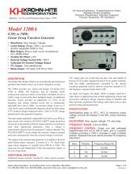
Table of ContentsModel <strong>3360</strong> SeriesModel 3362Model 3364iv
Model <strong>3360</strong> SeriesSection 1 - General DescriptionSECTION 1GENERAL DESCRIPTION1.1 IN TRO DUC TIONThe <strong>Krohn</strong>-<strong>Hite</strong> Model <strong>3360</strong> Fil ter Series (3361, 3362 and3364) are one, two or four chan nel fil ters pro vid ing a tun ablefre quency range from 0.1Hz to 200kHz; and with the 002 op -tion, the range is ex tended to 0.005Hz. The fre quency re sponsechar ac ter is tic is selectable to ei ther max i mally flat(Butterworth) for clean filtering in the frequency domain, orlinear phase (Bessel) to provide superior filtering of pulse orcom plex sig nals.Each channel of the <strong>3360</strong> Series is a selectable low-pass orhigh-pass, 4-pole fil ter pro vid ing an in put gain of up to 50dBand an out put gain of up to 20dB, selectable in 0.1dB steps. The<strong>3360</strong> Se ries will ac cept in put sig nals of ±10V peak at 0dB gainand has selectable ac or dc cou pling. Mem ory is avail able forstoring set-ups of the instrument which can be recalled laterwith a sim ple com mand. The fol low ing pages are the spec i fi ca -tions of the Model <strong>3360</strong> Series Filters.1.2 SPEC I FI CA TIONS (each chan nel)1.2.1 Func tionsLow-pass filter, high-pass filter.3362 and 3364, one or two channel(s) of band-pass orband-reject via external connections.1.2.2 Num ber of Chan nelsModelChannels3361 13362 2336441.2.3 Fil ter Char ac ter is ticsType: Selectable 4-pole Butterworth or 4-pole Bessel.Attenuation: 24dB/octave.Tunable Frequency Range fc: 0.1Hz to 200kHz; (option 002,0.005Hz).Frequency Resolution: 3 digits, ³1Hz fc; 0.001Hz, 2MHz.Stopband Attenuation: >100dB.Maximum Input: ±10V peak at 0dB gain, reduced in proportionto gain setting.Pre-Filter Gain: 0dB, 10dB, 20dB, 30dB, 40dB, 50dB, ±0.2dB.Post-Filter Gain: 0dB to 20dB selectable in 0.1dBsteps, ±0.2dB.Wideband Noise (2MHz bandwidth detector): 0dB gain,
Section 1 - General DescriptionOutput:Max i mum Volt age (open cir cuit): ±10V peak.Max i mum Cur rent: ±80mA peak.Im ped ance: 50 ohms.DC Off set: Ad just able to zero volts.1.2.4 Gen eralCrosstalk Between Channels: –80dB for fsig £200kHz, –70dBfor fsig >200kHz with input source £50 ohms.Memory: 9 stored set-ups (0 - 8).Self-Test Diagnostics: MPU checks unit upon power-up.Display indicates failure mode.Displays: 7 segment, green, LED; 0.3" high.Operating Temperature: 0°C to 50°C.Isolation to Chassis: ±200Vdc.Input/Output Connectors: BNC.Power: 3361, 9 watts; 3362, 16 watts; 3364, 30 watts.Dimensions and Weights: 3 1 2“ (9cm) high, 14" (35.56cm)wide, 12 1 2” (31.75cm) deep; 7 lbs (3.18kg) net, 9 lbs (4.09kg)shipping.1.2.5 Op tions002: extends low end cutoff to 0.005Hz.BK-330: Battery Option, up to 8 hours of operation,rechargable NiCad batteries (factory installation) for Models3361 and 3362 only.Rack Mount Kit: Part No. RK-314, permits installation of theModel <strong>3360</strong> Series into a standard 19" rack spacing.Extended 1 Year Warranty: Part No. EX<strong>3360</strong>.Specifications apply at 25°C, ±5°C.Model <strong>3360</strong> Series1-2
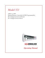
Model <strong>3360</strong> SeriesSection 2 - OperationSECTION 2OPERATION2.1 IN TRO DUC TIONThe Model 3361, 3362 and 3364 Filters are one, two or fourchannel filters respectively, providing a tunable frequencyrange of 0.1Hz to 200kHz (0.005Hz with op tion 002).Each chan nel is selectable low-pass or high-pass, 4-pole within put gain from 0dB to 50dB, selectable in 10dB steps; and out -put gain from 0dB to 20dB, selectable in 0.1dB steps.The input signal can be ±10V peak at 0dB gain and hasselectable ac or dc coupling. Mem ory is available for storingset-ups of the front panel settings which can be recalled laterwith a key stroke en try.Each mode of op er a tion will be ex plained in this sec tion.2.2 TURN-ON PRO CE DUREThe Model <strong>3360</strong> line voltage range has been pre set for ei ther115V or 230V, Norm, line volt age. When mak ing any changesto the line con nec tions, re move the power cord.To change the Norm/Low line set ting, re move the top cover toexpose the Norm/Low line switch lo cated near the rear panel,un der the back shield.To achieve ac cess to the 120V/240V con nec tions, re move thebot tom cover and change the con nec tions to the de sired volt ageas shown in Fig ure 2.1.Note: On early mod els, a 120V/240V switch was pro vided nextto the Norm/Low line switch.Bot tom View120V240VFig ure 2.1 Jumper Set tings for 120V/240V Op er a tion2-1
Section 2 - OperationModel <strong>3360</strong> SeriesModel 3364 Four Channel Filter120V240VJumper120V240VNormLowLineSwitchIn putVoltageRange(rms)Norm 108-132Low 90-110Norm 216-264Low 180-220Model3361In stall FuseModel3362Model3364.15A 1/4A 1/2A.1A 1/8A 1/4AWhen the self-test program has completed, the Model <strong>3360</strong>will re turn to the setup stored in stor age lo ca tion 0. The Model<strong>3360</strong> is now ready for op er a tion.2.4 OP ER A TION120V/240VJumper120V240VPower Con sump tion(watts)ModelModelModel3361336233648 14 269 16 308 14 269 16 30Set the 120V/240V and Norm/Low line switch and jump ers asneeded ac cord ing to the ta ble above.Be sure to change the fuse to the proper rating for the lineswitch set ting se lected. Re place the cover.Plug the line cord into the unit, then the ac out let.Af ter read ing the Self-Test fea ture, de scribed next, turn on theModel <strong>3360</strong>.2.3 SELF TESTWhen the Model <strong>3360</strong> is turned on, the microprocessor per -forms a self-test rou tine whereby the en tire RAM and ROM op -er a tion is ver i fied. If there is a mal func tion, such as a de fec tiveRAM or ROM, the word “bad” will appear in the DISPLAYfol lowed by a num ber 1 or 2. “bad 1” in di cates U16, mi cro pro -ces sor is de fec tive and a “bad 2” in di cates U17, EPROM is de -fective.2.4.1 Front Panel Con trols and Dis playChan nel Se lec tion(Models 3362 and 3364 only)The up [∆] control key below the CHANNEL display in cre -ments the chan nel num ber. The var i ous dis plays and in di ca torson the front panel (cut off fre quency, gains, etc.) per tain to thechan nel in di cated by this dis play.2.4.1.1 Set ting Cut off Fre quencyData en try keys [0] to [9], [.], [KILO] and [MEGA] set the nu -meric value of the cut off fre quency de sired. To se lect 1.5kHz,press the [1][.][5] data keys and parameter keys [KILO] and[FREQ]. The cut off fre quency for the chan nel se lected will bein di cated in Hertz on the four digit DIS PLAY (when [ALL CH]mode is selected, the frequency will be changed on all chan -nels). The KILO and FREQ keys will be lit.2.4.1.2 Digit Se lect/Fre quency In cre mentand Dec re mentWhen the [SHIFT] key is pressed, fol lowed by the DIGIT SE -LECT [∆] or [∇] keys, the FREQUENCY DIS PLAY will in ten -sify a digit. Pressing the [SHIFT] fol lowed by the [∆] or [∇] keyagain, will intensify the next digit or will turn the DIGIT SE -LECT off. The [∆] will move the in ten si fied digit to the left and2-2
Model <strong>3360</strong> SeriesSection 2 - Operationthe [∇] will move the in ten si fied digit to the right (di rec tion isla beled in red to the left of keys).Pressing the [∆] or [∇] keys will then in cre ment or dec re mentthe in ten si fied fre quency digit.2.4.1.3 Set ting In put Gain (Pre-Fil ter)Up [∆] and down [∇] IN PUT GAIN SET con trols in crease orde crease the in put am pli fier by 10dB. The two digit DIS PLAYwill indicate either 0dB, 10dB 20dB, 30dB, 40dB or 50dB.May also be set by en ter ing gain de sired di rectly on the key padand press ing ei ther the [∆] or [∇] gain key.2.4.1.4 Set ting Out put Gain (Post Fil ter)Up [∆] and down [∇] OUT PUT GAIN SET con trols in crease ordecrease the output amplifier by 0.1dB steps from 0dB to20.0dB. For gains 10dB, only 1dB res o lu tion is dis played; how ever, the up[∆] and down [∇] keys continue to increment and decrementthe gain by 0.1dB. The full 3-digit res o lu tion may be seen in themiddle display by press ing [SHIFT] the [∆] or [∇] key underthe out put gain dis play. Also for gains >10dB, the dec i mal pointis off for whole dB’s (10, 11, 12, etc.) but on for frac tional (10.1– 10.9, 11.1 – 11.9, etc.). Gain may also be set by en ter ing gainde sired di rectly on the key pad and press ing ei ther the [∆] or [∇]gain key.2.4.1.5 Butterworth or BesselSe lec tion – [TYPE]When [TYPE] is pressed once, DIS PLAY in di cates the pres entfilter type, “bu.” (Butterworth) and “bES.” (Bessel). Whenpressed again, the type will change (i.e. if the type was “bES.” ,the change will be to “bu.”.)2.4.1.6 Low-Pass and High-PassOp er a tion – [MODE]When [MODE] is pressed once, DIS PLAY in di cates the pres -ent fil ter type, “h.P.” (high-pass) and “L.P.” (low-pass). Whenpressed again, the type will change (if the type was “L.P.” , thechange will be to “h.P.”).2.4.1.7 Vari able Band-Pass Op er a tion(Models 3362 and 3364 only)To obtain Band-Pass op er a tion with 24dB per oc tave at ten u a -tion pro ceed as fol lows:Set chan nel 1 to high-pass mode (this will con trol the low cut offfre quency). Set chan nel 2 to low-pass (this will con trol the highcut off fre quency). Con nect the in put sig nal to chan nel 1 in put,con nect the chan nel 1 out put to the chan nel 2 in put and con nectthe load to the chan nel 2 out put. For the Model 3364, the samecan be done with chan nels 3 and 4 re spec tively.The min i mum pass-band is ob tained by set ting the high cut offfre quency equal to the low cut off fre quency. In this con di tionthe in ser tion loss is nom i nally 6dB (in the Butterworth mode)and the –3dB cut off fre quen cies oc cur at 0.58 and 1.7 times themid-band fre quency. In ser tion loss may be made-up by set tingout put gains to +6dB.2.4.1.8 Vari able Band-Re ject Op er a tion(Models 3362 and 3364 only)To ob tain Band-Re ject or Notch op er a tion, pro ceed as fol lows:Con nect the two chan nels in par al lel by con nect ing the in putsig nal to the in put of each chan nel si mul ta neously. The out putfrom both chan nels should be added through two equal ex ter -nal re sis tors in se ries with each out put. The junc tion of these re -sis tors be comes the out put of the fil ter. It is rec om mended thatthe resistors be approximately 1k ohms and of the carbon ormetal film type if the fil ter is used at higher fre quen cies. If thetwo re sis tors are not equal, the gain on one side of the notch willbe different than the gain of the other. Insertion loss may bemade-up by set ting out put gains to +6dB.Set chan nel 1 for low-pass and chan nel 2 for high-pass, and ad -just the cut off of each chan nel for the max i mum re jec tion. Theideal notch oc curs when set ting the low cut off (low-pass) to 0.5and the high cut off (high-pass) to 1.5 notch. In ser tion loss maybe made-up by set ting out put gains to +6dB.Caution: Do not ex ceed spec i fied volt age at ter mi nals.2.4.1.9 AC/DC Cou plingPressing the [SHIFT] key, followed by the [TYPE] key, willdisplay the pres ent input cou pling, in di cat ing “AC” or “dC”.Press [SHIFT] [TYPE] again to toggle be tween AC and DC.2.4.1.10 Dif fer en tial/Sin gle-Ended In putLED indicators are provided on the front panel to indicatewhich in put(s) is (are) ac tive. Pressing [SHIFT] and then the[+ONLY] key un der the Input Gain Display will select sin -gle-ended in put mode, only the LED be side the +In put of theselected channel will be lit. Pressing [SHIFT] and then the[DIFF] key, will select the differential input mode and bothLEDs be side the se lected chan nel will be lit.2.4.1.11 Storing a Fil ter Setup – [STORE]There are 9 stor age lo ca tions for stor ing front panel fil ter set -ups. The locations are num bered 0 through 8. When [SHIFT][RECLL][STORE] is first pressed, the DIS PLAY in di cates thenumber of the next memory lo ca tion avail able. For ex am ple,the DISPLAY will indicate the following: “n=05”. Pressing[RECLL] again will store the en tire fil ter set-up into that mem -ory location. If an other mem ory lo ca tion is de sired, en ter thatlo ca tion on the key board and then press [SHIFT][RECLL].When [SHIFT] [RECLL] is preceded by a num ber(0-8), the <strong>3360</strong> will store the cur rent fil ter set-up into the mem -ory lo ca tion se lected.When [SHIFT] [RECLL] is pressed to in di cate the next mem -ory lo ca tion only, press ing the clear en try key [CE] will re storethe DIS PLAY to the cut off fre quency set ting. The fil ter set tingsstored in mem ory lo ca tion 0 is automatically re called atturn-on.2-3
Section 2 - OperationModel <strong>3360</strong> Series2.4.1.12 Re calling a Fil ter Setup – [RECLL]When [RECLL] is pre ceded by a num ber, it will re call the fil terset-up which was stored in the memory location selected.Selectable lo ca tions are 0 to 8.When first pressed, the DIS PLAY in di cates the num ber of thememory lo ca tion to be re called. For ex am ple, the DISPLAYwill in di cate the fol low ing: “n=05”. Pressing the [RCLL] keyagain will re call the en tire fil ter set-up from mem ory lo ca tion“05”.When pressed to indicate the memory location to be recalledonly, press ing the [CE] (clear en try key) will re store the DIS -PLAY to the cut off fre quency set ting.Mem ory lo ca tion 0 is au to mat i cally re called at turn-on.2.4.1.13 Clear En try Key – [CE]When en ter ing a nu meric value in the key board, but not spec i -fy ing a pa ram e ter, press ing the clear en try key will re store theDISPLAY to the cur rent cut off fre quency set ting.When a nu meric value and its pa ram e ter has been en tered andthe nu meric value is then changed, press ing the [CE] key willrestore DISPLAY to the previous value of that parameter.Pressing the [CE] key continuously will tog gle between thepre vi ous key pad en try and the pres ent en try.When either the [STORE] or [RECALL] key is pressed, thenext memory location will be indicated on the DISPLAY.Pressing the [CE] key will re store DIS PLAY to the cur rent cut -off fre quency set ting.2.6 FIL TER CHAR AC TER IS TICS2.6.1 Am pli tude Re sponseEach channel of the Model <strong>3360</strong> can operate in either thelow-pass or high-pass mode at 24dB/octave attenuation andprovide either maximally flat (Butterworth) amplitude re -sponse or lin ear phase (Bessel) op er a tion. Com par a tive am pli -tude re sponse char ac ter is tics in both modes are shown in Fig -ure 2.2A and 2.2B.Figure 2.2A Low-Pass Amplitude Response2.4.1.14 All Chan nel Mode – [ALL CH](Models 3362 and 3364)When [ALL CH] is pressed, the LED in the [ALL CH] key willlight; and when frequency, input/output gain, type, mode,+only or diff in put, and/or cou pling is en tered or changed, thenew set ting will be en tered in all chan nels of the fil ter.2.5 REAR PANEL DC LEVEL ADJ.The Model <strong>3360</strong> rear panel has 2, 4 or 8 out put dc level ad just -ments. The fol low ing pro ce dure is for ad just ing the out put dclevel to zero volts for any channel.2.5.1 DC Level Adj. (Rear Panel) HPFigure 2.2B High-Pass Amplitude ResponseSet the fil ter to HP at 1.1kHz. Ad just HP for 0V at fil ter out put.2.5.2 DC Level Adj (Rear Panel) OutAt any fre quency set ting, the out put dc level may be ad justed tozero volts for each chan nel with the rear panel, screw driver ad -just, out put dc level con trol.2-4
Section 2 - OperationModel <strong>3360</strong> SeriesThis page in ten tion ally left blank.2-6