Series LX/LC6D - SMC Pneumatics (Ireland)
Series LX/LC6D - SMC Pneumatics (Ireland)
Series LX/LC6D - SMC Pneumatics (Ireland)
- No tags were found...

You also want an ePaper? Increase the reach of your titles
YUMPU automatically turns print PDFs into web optimized ePapers that Google loves.
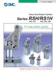
Electric Actuator<strong>LX</strong>/<strong>LC6D</strong>Short Stroke Electric Actuator<strong>Series</strong> <strong>LX</strong>Stepper motorLow Profile Slide Table<strong>Series</strong> <strong>LX</strong>FWithoutbrakeP. 1Guide Rod Type<strong>Series</strong> <strong>LX</strong>PP. 5WithoutbrakeHigh Rigidity Slide Table Type<strong>Series</strong> <strong>LX</strong>SWithoutbrakeP. 9With brakeWith brakeLow Particulate P. 13Generation Specification<strong>Series</strong> <strong>LX</strong>F<strong>Series</strong> <strong>LX</strong>P<strong>Series</strong> <strong>LX</strong>SStepper Motor Driver<strong>Series</strong> <strong>LC6D</strong>P. 26StepperMotorDriver<strong>LC6D</strong>To power supplyPositioning unit(Not incl. To be provided by customer.)Electric ActuatorFeatures 1
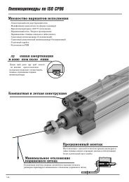
<strong>Series</strong> <strong>LX</strong>Electric ActuatorShort Stroke Type with Three Guide Variations<strong>LX</strong>/<strong>LC6D</strong><strong>Series</strong> <strong>LX</strong>FSpace savingLow profile slide table type with stepper motorThickness: 31mmGuide rod type with stepper motor<strong>Series</strong> <strong>LX</strong>PUse as lifterHigh rigidity slide table type with stepper motor<strong>Series</strong> <strong>LX</strong>SHigh moment loadFeatures 2
Electric Actuator<strong>LX</strong>/<strong>LC6D</strong>Improved body mounting accuracy: ±0.07mm±0.07±0.07YReferenceplaneXAn NC machined reference planeand positioning pin hole providedon each series body improvesthe repeatability of actuator bodymounting.Variations<strong>Series</strong>Motor type(Stepper motor)Guide typeMountingorientationLead screw typeSensorMade to order<strong>LX</strong>F5 phaseDirect acting guideHorizontalAuto switchProximity switch<strong>LX</strong>P<strong>LX</strong>S2 phase5 phaseBall bushingHigh rigiditydirect acting guideHorizontalVerticalBall screwSlide screwAuto switchAuto switchProximity switchLow particulate generationspecificationApplicationsStoringFixed speed gluingApplication/FillingTransfer without impactAccurate pitch feedFilling into boxes with varying heightInching feed for work piece thicknesssynchronized with the conveyorTestingMarking4 1234567 890123C4 1234567 890123B4 1234567 890123AMultiple point positioning applicablefor multiple product typesTransfer with theuse of barcode readerCenter line marking of tiresfor varying tire widthFeatures 3
Features 4
Electric Actuator<strong>LX</strong>/<strong>LC6D</strong>Simplified Selection Flow ChartShort Stroke Type Electric Actuator <strong>Series</strong> <strong>LX</strong> (Stepper Motor)<strong>Series</strong>Low profileslide table type<strong>Series</strong> <strong>LX</strong>FGuide rod type<strong>Series</strong> <strong>LX</strong>PHigh rigidity slide table type<strong>Series</strong> <strong>LX</strong>SLowparticulategeneration——————————————————BrakeWithoutmotorbrakeWithoutmotorbrakeWithmotorbrakeWithoutmotorbrakeWithmotorbrakeWork loadkg232346234534.569101245Maximum speedmm/s30303030302008010020020010080100200200100801002002001001008020020010010080Positioningrepeatabilitymm±0.05±0.03±0.05±0.05±0.03±0.05±0.05±0.03±0.05±0.05±0.03±0.05±0.03Lead screw Guide typeSlide screwBall screwSlide screwSlide screwBall screwSlide screwSlide screwBall screwSlide screwSlide screwBall screwSlide screwBall screwDirect actingguideBall bushingguideHigh rigiditydirect actingguideMotorManufacturerSanyo Denki Co., Ltd.Sanyo Denki Co., Ltd.Sanyo Denki Co., Ltd.Features 5
Electric Actuator<strong>LX</strong>/<strong>LC6D</strong>Phases5 phase5 phase5 phase5 phase5 phase2 phase5 phase2 phase5 phase2 phase5 phase2 phase5 phase2 phase5 phase2 phase5 phase2 phase5 phase2 phase5 phase2 phase5 phase2 phase5 phase2 phase5 phase2 phase5 phase2 phase5 phase2 phase5 phase2 phase5 phase2 phaseStandard stroke (mm) and Maximum speed (mm/s)25 50 75 100 125 150 175 200to 200to 30to 80to 100to 200to 200to 100to 30to 30to 80to 80to 100to 200to 200to 100to 30to 30to 80to 80to 100to 200to 200to 100to 100to 30to 30to 80to 80to 200to 200to 100to 100to 30to 30to 80to 80Model<strong>LX</strong>FH5SB<strong>LX</strong>FH5BC<strong>LX</strong>FH5BD<strong>LX</strong>FH5SA<strong>LX</strong>PB5SB<strong>LX</strong>PB2SB<strong>LX</strong>PB5SA<strong>LX</strong>PB2BC<strong>LX</strong>PB5BC<strong>LX</strong>PB2BD<strong>LX</strong>PB5BD<strong>LX</strong>PB2SA<strong>LX</strong>PB5SB-B<strong>LX</strong>PB2SB-B<strong>LX</strong>PB5SA-B<strong>LX</strong>PB2BC-B<strong>LX</strong>PB5BC-B<strong>LX</strong>PB2BD-B<strong>LX</strong>PB5BD-B<strong>LX</strong>PB2SA-B<strong>LX</strong>SH5SB<strong>LX</strong>SH2SB<strong>LX</strong>SH5SA<strong>LX</strong>SH2SA<strong>LX</strong>SH5BC<strong>LX</strong>SH2BC<strong>LX</strong>SH5BD<strong>LX</strong>SH2BD<strong>LX</strong>SH5SB-B<strong>LX</strong>SH2SB-B<strong>LX</strong>SH5SA-B<strong>LX</strong>SH2SA-B<strong>LX</strong>SH5BC-B<strong>LX</strong>SH2BC-B<strong>LX</strong>SH5BD-B<strong>LX</strong>SH2BD-BFeatures 6
Low Profile Slide Table Type<strong>Series</strong> <strong>LX</strong>FSlide screw optionActuator configurationF Flat table typeH5<strong>LX</strong> F H 5 SGuide typeDirect acting guideBall screw optionMotor type5 phase stepper motorLead screw typeS Slide screwLead screw leadAB6mm12mmNilS255075100Stroke25mm50mm75mm100mm50Home position switchNoneYes (cable length 0.3m)SM9N1 QCE markingNumber of auto/proximity switches11 pc.When using both auto andproximity switches, list the22 pcs.proximity switch part numberafter the autoswitch part66 pcs.number.Example) M9N1G2Auto switch type……SymbolNilM9NM9PF9GF9HF9GLF9HLM9BM9NLM9PLM9BLModelD-M9ND-M9PD-F9GD-F9HD-F9GLD-F9HLD-M9BD-M9NLD-M9PLD-M9BLWiring/Output type3 wire/NPN3 wire/PNP3 wire/NPN3 wire/PNP3 wire/NPN3 wire/PNP2 wire3 wire/NPN3 wire/PNP2 wireProximity switch typeSymbolGNGGDGBGDBGUGUBModelGXL-8FGXL-8FIGXL-8FBGXL-8FIBGXL-8FUGXL-8FUBWiring/Output typeLead wirelength (m)Without autoswitch0.50.50.50.5330.5333With sensor rail, without proximity switch3 wire/NPN3 wire/NPN3 wire/NPN3 wire/NPN2 wire/solid state2 wire/solid stateLead wirelength (m)111111ContactN.O. (A contact)N.O. (A contact )N.C. (B contact)N.C. (B contact)N.C. (B contact)N.C. (B contact)N.O. (A contact)N.O. (A contact)N.O. (A contact)N.O. (A contact)ContactN.O. (A contact)N.O. (A contact)N.C. (B contact)N.C. (B contact)N.O. (A contact)N.C. (B contact)Actuator configurationF Flat table typeH5<strong>LX</strong> F H 5 BGuide typeDirect acting guideMotor type5 phase stepper motorLead screw typeB Ball screwLead screw leadCD2mm5mm50SGD1QCE markingNumber of proximity switches11 pc.22 pcs.…6Proximity switch typeSymbolGNGGDGBGDBGUGUBModelGXL-8FGXL-8FIGXL-8FBGXL-8FIBGXL-8FUGXL-8FUB…6 pcs.Wiring/Output typeWith sensor rail, without proximity switch3 wire/NPN3 wire/NPN3 wire/NPN3 wire/NPN2 wire/solid state2 wire/solid stateLead wirelength (m)111111ContactN.O. (A contact)N.O. (A contact)N.C. (B contact)N.C. (B contact)N.O. (A contact)N.C. (B contact)255075100Stroke25mm50mm75mm100mmNilSHome position switchNoneYes (cable length 0.3m)1
Electric Actuator<strong>LX</strong>/<strong>LC6D</strong>SpecificationsMotorLead screwLead (mm)Position repeatabilitySpeed (mm/s) Note1Work load horizontal (kg) Note2Guide typeOperating temperature range °CHome position switchApplicable driverCE marking accesoriesBody WeightStandard strokeWeight (kg)5 phase stepper (without brake)Slide screw ø8mm Ball screw ø8mm6122 5± 0.05mm± 0.03mm6 to 100 12 to 200 2 to 30 5 to 803(2) 2(2) 3(2) 3(2)Direct acting guide5 to 40 (with no condensation)Photo micro sensor EE-SX672 (Refer to page 36)<strong>LC6D</strong>-507AD-Q / <strong>LC6D</strong>-507AD-P1-X316Holding plate: MB1 (1 pc.) Phillips countersunkhead screw M3 x 6L (1 pc.) Phillips bindinghead screw: M3 x 4L (2 pc.), Toolhed lock washerM3 (2 pc.) Binding Band: T18S (1 pc.)250.8501.0751.11001.2Note 1) As vibration may increase with slower speed, it is advised that a minimun motor speed of 1rps isused (e.g 6mm/s for 6mm lead).Note 2) When mounting a work piece on the actuator's end plate, the max workload should be that specifiedbetween the ().Allowable Moment (N⋅m)Allowable static momentPitchingRollingYawing434m : Transfer load (kg)L : Overhang to work piececentre of gravity (mm)a : Work piece acceleration(mm/sec²)Me: Dynamic momentAllowable dynamic momentLoadModelmovement directionPitchingRollingYawingL1MerL3maMepL2aMey20001000Refer to page 25 for deflection data.mmL1 (mm)L2 (mm)L3 (mm)0a = 1000300a = 2000200a = 30001000a = 10002000a = 2000a = 300010000a = 1000a = 2000a = 3000<strong>LX</strong>F1 2Transfer load m (kg)1 2Transfer load m (kg)1Transfer load m (kg)23332
<strong>LX</strong>FH5S∗–∗∗∗∗–∗∗∗∗–QElectric Actuator<strong>LX</strong>/<strong>LC6D</strong>Dimensions/<strong>LX</strong>FH5Scale: 35%5 Stroke + 113(5) 2-M2.5 x 0.45 depth 2(5)7262121018.52-M4 x 0.7thread depth 935252217.5ø5H9 +0.0300 depth 532 528G582-M3 x 0.5D-M4 x 0.7 (for work piece mounting) 12 2-M3thread depth 5 Effective thread4-ø8 506depth 4 (PE terminal) ∗1.5 [5.5] ∗∗ 6Photo micro sensorwire (300mm)10 (39.5) EMotor wire (300mm)Stroke + 135∗∗ The dimension inside [ ] shows the location at which the home position switch operates.Stroke + 1261059 F21329.510.52.520(5.5)(4)31102530.5(3.5)1 ±0.213(6)8+0.0305H9 depth 50(15)10.531M3 x 0.5Effective thread depth 4 (PE terminal)243.325.5Label80.515H9 +0.0300depth 5535.88T-slot dimension (2/1)ø5H9 +0.0300 depth 5Phillips binding headscrew (included)M3 x 4lCrimping terminalToothed lockwasher (included)Binding band (included)(11.5) 38 E∗ When using a PE terminal, use accessoriesincluded as shown on the left.Phillips countersunkhead screw (included)M3 x 6l64-M5 x 0.8 (for body mounting) thread depth 8Holding plate(included)Model<strong>LX</strong>FH5-25<strong>LX</strong>FH5-50<strong>LX</strong>FH5-75<strong>LX</strong>FH5-100D4466E60909090F30606060G(50)(50)1001003
Guide Rod Type<strong>Series</strong> <strong>LX</strong>PSlide screw optionActuator configurationP Guide rod type5B25<strong>LX</strong> P BGuide typeBall bushingMotor type2 phase stepper motor5 phase stepper motorLead screw typeS Slide screwLead screw leadABBall screw optionActuator configurationP Guide rod typeB25<strong>LX</strong> P BGuide typeBall bushingMotor type2 phase stepper motor5 phase stepper motorS6mm12mmLead screw typeB Ball screwCDBLead screw lead2mm5mm50751001251501752005075100125150175200Stroke100 S B M9N50mm75mm100mm125mm150mm175mm200mmStrokeHome position switchNilSNilSBrakeNilBWithout brakeWith brake1NoneYes (cable length 0.3m)QCE markingNumber of auto switches12Auto switch typeSymbolNilM9NM9PF9GF9HF9GLF9HLM9BM9NLM9PLM9BL100 S B M9N50mm75mm100mm125mm150mm175mm200mmBrakeNilBWithout brakeWith brakeHome position switchNoneYes (cable length 0.3m)6…ModelD-M9ND-M9PD-F9GD-F9HD-F9GLD-F9HLD-M9BD-M9NLD-M9PLD-M9BL11 pc.2 pcs.…6 pcs.Wiring/ Lead wireOutput type length (m)Without autoswitch3 wire/NPN3 wire/PNP3 wire/NPN3 wire/PNP3 wire/NPN3 wire/PNP2 wire3 wire/NPN3 wire/PNP2 wireQCE marking0.50.50.50.5330.5333Number of auto switches12Auto switch typeSymbolNilM9NM9PF9GF9HF9GLF9HLM9BM9NLM9PLM9BL6…ModelD-M9ND-M9PD-F9GD-F9HD-F9GLD-F9HLD-M9BD-M9NLD-M9PLD-M9BL1 pc.2 pcs.…6 pcs.Wiring/ Lead wireOutput type length (m)Without autoswitch3 wire/NPN3 wire/PNP3 wire/NPN3 wire/PNP3 wire/NPN3 wire/PNP2 wire3 wire/NPN3 wire/PNP2 wire0.50.50.50.5330.5333ContactN.O. (A contact)N.O. (A contact )N.C. (B contact)N.C. (B contact)N.C. (B contact)N.C. (B contact)N.O. (A contact)N.O. (A contact)N.O. (A contact)N.O. (A contact)ContactN.O. (A contact)N.O. (A contact )N.C. (B contact)N.C. (B contact)N.C. (B contact)N.C. (B contact)N.O. (A contact)N.O. (A contact)N.O. (A contact)N.O. (A contact)
Electric Actuator<strong>LX</strong>/<strong>LC6D</strong>SpecificationsMotorLead screwLead (mm)Position repeatability (mm)Speed (mm/s) Note 1)HorizontalNote 2)Work load (kg)VerticalNote 2)Guide typeOperating temperature range °CHome position switchBrake Modelspecifications Static torque(Electromagnetic Rated voltagebrake) Power consumptionApplicable driverCE marking accessories2 phase stepper motor (with/without brake)Slide ø8mmBall ø8mm6mm±0.056 to 1006512mm±0.0512 to 200332mm±0.032 to 30655mm±0.035 to 806<strong>LC6D</strong>-220AD-Q / <strong>LC6D</strong>-220AD-P1-X3166mm±0.056 to 10045 4Ball bushing5 to 40 (with no condensation)Photo micro sensor EE-SX673(refer to page 36)De-energized operating type0.1Nm or more24VDC ±5%5W5 phase stepper motor (with/without brake)Slide ø8mmBall ø8mm12mm±0.0512 to 200222mm±0.032 to 3065Holding plate: MB1 (1pc.) Phillips countersunk head screw M3 x 6L (1pc.) Phillips bindinghead screw: M3 x 4L (2pcs). Toothed lock washer M3 (2pcs). Binding band: T18S (1pc).5mm±0.035 to 8065<strong>LC6D</strong>-507AD-Q / <strong>LC6D</strong>-507AD-P1-X316Body WeightStandard strokeWith brakeWeight (kg)Without brake502.22752.42.21002.52.31252.62.81503.02.81753.12.92003.33.1Note 1) As vibration may increase with slower speed, it is advised that a minimum motor speed of 1rps is used (e.g 6mm/s for 6mm lead).Note 2) Based on the operating conditions, establish a separate guide when exceeding the maximum allowable lateral load.Allowable loads and moments for horizontal and vertical applicationsLifter Operation RangeOperating ConditionsThis is the operating range for ball bushings.Use within the allowable thrust range.Lm50 to 200mm strokeLmAllowable lateral load (F)StrokeLoad (N)504275421004012542150321752420017FAllowable plate rotation torque (T)Stroke Torque (N⋅m)502.87752.471002.171252.381502.161751.982001.82Load weight m (kg)101125 to 200mm stroke50 to 100mm strokeFTPlate non-rotating accuracy (θ)Non-rotating accuracy (θ)±0.09°0.110 50 100Eccentric distance L (mm)Refer to page 25 for deflection data.+θ–θ6
Electric Actuator<strong>LX</strong>/<strong>LC6D</strong>Dimensions/<strong>LX</strong>PB25When two dimensions are shown,the top dimensions is for 50 to 75 and 100mm stokes, andthe bottom dimension is for 125, 150, 175, and 200mm strokes.Scale: 25%40.5With brake63.512125Without brakeSection F detail(Scale: 2/1)7888Stroke + 216 (Stroke: 50 to 100)Stroke + 233 (Stroke: 125 to 200)Section F4-M6 x 197.54.5C section21.54-M6 x 1 depth 101010 [16.5] ∗∗B∗∗ The dimension inside [ ] shows the locationat which the home position switch operates.184-ø5.6 +0.14-ø9.55.48.450147.594917834 ±0.02643430.505.5 1243Cross section BB0ø4H9 +0.030depth 64.5ø4H9 +0.030026637310B30 D2-M3 x 0.5 (PE terminal) ∗Effective thread depth 7Stroke + 181Stroke + 198Motor wire (300mm)Photo micro sensor wire (300mm)Phillips binding headscrew (included)M3 x 4lCrimping terminal4H9 +0.030036Section C detail(Scale: 2/1)38ø4H9 +0.030M3 x 0.5 (PE terminal) ∗Effective thread depth 4Stroke + 104Stroke + 121337.549LabelToothed lock washer(included)0 depth 6EBinding band (included)Phillips countersunk headscrew (included)M3 x 6l34Holding plate(included)C section30 D4-M6 x 1∗ When using a PE terminal, use accessories included as shown above.Model<strong>LX</strong>PB- 50<strong>LX</strong>PB- 75<strong>LX</strong>PB-100<strong>LX</strong>PB-125<strong>LX</strong>PB-150<strong>LX</strong>PB-175<strong>LX</strong>PB-200D44120(mm)E52907
Electric Actuator<strong>LX</strong>/<strong>LC6D</strong>Construction<strong>Series</strong> <strong>LX</strong>PParts listNo.1234567891011DescriptionMotorRolled screwNutCouplingBearingBodyMounting plateBall bushingGuide rodTubeSensor pinMaterial——Alloy steelResin————Aluminum alloyMild steel——Bearing steelAluminum alloyStainless steelNoteStepper motorAnodizedNickel platedChrome platedAnodizedParts listNo.121314151617181920212223DescriptionPhoto micro sensorLock nutStopper nutBumper boltBumperMotor coverTension ringCable capPlugMagnetAdaptorPlate mounting boltMaterial——Carbon steelAluminum alloyBearing steelResinResinStainless steel——Aluminum alloyCarbon steelNoteBlack zinc chromatedNickel platedNickel plated8
High Rigidity Slide Table TypeWith Motor Brake/Without Motor Brake<strong>Series</strong> <strong>LX</strong>SSlide screw optionActuator configurationS Slide table type9H25<strong>LX</strong> S H S 100 S B M9N 1Guide typeDirect acting guideMotor type2 phase stepper motor5 phase stepper motorLead screw typeS Slide screwLead screw leadABBall screw optionActuator configurationS Slide table typeH25Motor type2 phase stepper motor5 phase stepper motor6mm12mmNilSLead screw typeB Ball screwCD5075100125150Stroke50mm75mm100mm125mm150mmHome position switch2mm5mmNoneYes (cable length 0.3m)NilBBrakeWithout brakeWith brakeQCE markingNumber of auto switches12…6Auto switch type1 pc.2 pcs.…6 pcs.SymbolNilM9NM9PF9GF9HF9GLF9HLM9BM9NLM9PLM9BLModelD-M9ND-M9PD-F9GD-F9HD-F9GLD-F9HLD-M9BD-M9NLD-M9PLD-M9BLWiring/Output type3 wire/NPN3 wire/PNP3 wire/NPN3 wire/PNP3 wire/NPN3 wire/PNP2 wire3 wire/NPN3 wire/PNP2 wireProximity switch typeSymbolGNGGDGBGDBGUGUB<strong>LX</strong> S H B 100 S B M9N 1Guide typeDirect acting guideLead screw lead5075100125150Stroke50mm75mm100mm125mm150mmHome position switchNilSNoneYes (cable length 0.3m)NilBBrakeWithout brakeWith brakeModelGXL-8FGXL-8FIGXL-8FBGXL-8FIBGXL-8FUGXL-8FUBWiring/Output typeLead wirelength (m)Without autoswitch0.50.50.50.5330.5333With sensor rail, without proximity switch3 wire/NPN3 wire/NPN3 wire/NPN3 wire/NPN2 wire/solid state2 wire/solid stateQLead wirelength (m)111111CE markingNumber of auto switches12…6Auto switch type1 pc.2 pcs.…6 pcs.SymbolNilM9NM9PF9GF9HF9GLF9HLM9BM9NLM9PLM9BLModelD-M9ND-M9PD-F9GD-F9HD-F9GLD-F9HLD-M9BD-M9NLD-M9PLD-M9BLWiring/Output type3 wire/NPN3 wire/PNP3 wire/NPN3 wire/PNP3 wire/NPN3 wire/PNP2 wire3 wire/NPN3 wire/PNP2 wireProximity switch typeSymbolGNGGDGBGDBGUGUBModelGXL-8FGXL-8FIGXL-8FBGXL-8FIBGXL-8FUGXL-8FUBLead wirelength (m)Without autoswitchWiring/Output type0.50.50.50.5330.5333With sensor rail, without proximity switch3 wire/NPN3 wire/NPN3 wire/NPN3 wire/NPN2 wire/solid state2 wire/solid stateLead wirelength (m)111111When using both auto andproximity switches, list theproximity switch part numberafter the autoswitch partnumber.Example) M9N1G2ContactN.O. (A contact)N.O. (A contact )N.C. (B contact)N.C. (B contact)N.C. (B contact)N.C. (B contact)N.O. (A contact)N.O. (A contact)N.O. (A contact)N.O. (A contact)ContactN.O. (A contact)N.O. (A contact)N.C. (B contact)N.C. (B contact)N.O. (A contact)N.C. (B contact)When using both auto andproximity switches, list theproximity switch part numberafter the autoswitch partnumber.Example) M9N1G2ContactN.O. (A contact)N.O. (A contact )N.C. (B contact)N.C. (B contact)N.C. (B contact)N.C. (B contact)N.O. (A contact)N.O. (A contact)N.O. (A contact)N.O. (A contact)ContactN.O. (A contact)N.O. (A contact)N.C. (B contact)N.C. (B contact)N.O. (A contact)N.C. (B contact)
Electric Actuator<strong>LX</strong>/<strong>LC6D</strong>SpecificationsMotorLead screw typeLead (mm)Position repeatability (mm)Speed (mm/s) Note 1)HorizontalNote 2)Work load (kg)VerticalNote 2)Guide typeOperating temperature range °CHome position switchBrake Modelspecifications Static torque(Electromagnetic Rated voltagebrake) Power consumptionApplicable driverCE marking accessories2 phase stepper motor (with/without brake)Slide ø8mmBall ø8mm6mm±0.056 to 1009(4)4(4)12mm±0.0512 to 2004.5(4)2(2)2mm±0.032 to 3010(4)5(4)5mm±0.035 to 8010(4)<strong>LC6D</strong>-220AD-Q / <strong>LC6D</strong>-220AD-P1-X3165(4) 2(2)High rigidity direct acting guide5 to 40 (with no condensation)Photo micro sensor EE-SX673(refer to page 36)De-energized operating type0.1Nm or more24VDC ±5%5W5 phase stepper motor (with/without brake)Slide ø8mmBall ø8mm6mm±0.056 to 1006(4)12mm±0.0512 to 2003(3)1(1)2mm±0.032 to 3010(4)5(4)Holding plate: MB1 (1pc.) Phillips countersunk head screw M3 x 6L (1pc.) Phillips bindinghead screw: M3 x 4L (2pcs). Toothed lock washer M3 (2pcs). Binding band: T18S (1pc).5mm±0.035 to 8010(4)5(4)<strong>LC6D</strong>-507AD-Q / <strong>LC6D</strong>-507AD-P1-X316Body WeightStandard strokeWith brakeWeight (kg)Without brake502.11.9752.32.11002.52.31252.72.51502.92.7Note 1) As vibration may increase with slower speed, it is advised that a minimum motor speed of 1rps is used (e.g 6mm/s for 6mm lead).Note 2) When mounting a work piece on the actuators end plate, the max. workload should be that specified between the ().Allowable Moment (N⋅m)Allowable dynamic momentLoadModelmovement directionaPitchingRollingYawingMerL3L1mMepaMeyL2mmL1 (mm)L2 (mm)L3 (mm)10000500100050000<strong>LX</strong>S2000a =1000a = 20001000a = 30005 10Transfer load m (kg)a = 1000 to 30005 10Transfer load m (kg)a = 1000 to 30005 10Transfer load m (kg)Note) Obtain maximun load and speed from thespecifications table.Allowable dynamic momentLoadmovement directionPitchingYawingL1L3mmModelMepMeyaaL1 (mm)L3 (mm)Allowable static momentPitchingRollingYawing15.715.77.84m: Transferload (kg)L: Overhang to work piececentre of gravity (mm)a: Work piece acceleration(mm/sec 2 )Me: Dynamic moment1000500100005000<strong>LX</strong>Sa = 1000 to 30005 9Transfer load m (kg)a = 1000 to 30005 9Transfer load m (kg)10
<strong>LX</strong>SH ∗ S ∗ — ∗∗∗∗B — ∗∗∗∗ — Q<strong>LX</strong>SH ∗ S ∗ — ∗∗∗∗B — ∗∗∗∗ — QElectric Actuator<strong>LX</strong>/<strong>LC6D</strong>Dimensions/<strong>LX</strong>SH25With brakeScale: 25%Brake electrical circuit+24VBrown[Yellow]Stroke + 246160VWhite[Yellow]Note) A contact protection circuit is requiredwhen connecting a brake.5975.5Without brakeFG x ICrimping terminalToothed lockwasher (included)Binding band (included)2-M6thread depth 1310.56.5(39)104 5.56.5T-slot A dimension<strong>LX</strong>SH- 50<strong>LX</strong>SH- 75<strong>LX</strong>SH-100<strong>LX</strong>SH-125<strong>LX</strong>SH-15011Phillips binding headscrew (included)M3 x 4l∗ When using a PE terminal, use accessoriesincluded as shown above.Model583.3D-ø5.1 throughRefer to Cross section C-C, bottom view.ø5H9 +0.0300 depth 532 5E-M52-M3 x 0.56Thread depth 10Effective thread depth 4 (PE terminal) ∗[18] ∗∗ 15Stroke + 127LabelPhillips countersunkhead screw (included)2-M2.5thread depth 4 8M3 x 6lJ2525Holding plate 27 J x K(included)Stroke + 22013 Stroke + 12715275.8521 3764636T-slotBdimensionD44446E66888(5) 46.5 0.528F107112122132112385H9 +0.0300depth 5Uø4H9 +0.0300 depth 44H9 +0.0300depth 4NN x PCC3.53∗∗ The dimension inside [ ] shows the location atwhich the home position switch operates.G5565758565I11112J6575657075K22333510L-M6Refer to Crosssection C-C.L66668N5565758565P22223(mm)U5247474747Motor wire (300mm)Photo micro sensor wire (300mm)36: T-slot pitch39T-slot ABody mountingreference plane6.527.52820(52)1 ±0.2 (ø5.1)Cross Section C-C19T-slot B58Work piece mountingreference plane
Electric Actuator<strong>LX</strong>/<strong>LC6D</strong>Construction<strong>Series</strong> <strong>LX</strong>SParts listNo.12345678910111213Description Material NoteBodyTableAdaptorPlateTubeRod assemblyStopper AStopper BDirect acting guide(block, rail)Rolled screw(shaft only)Tension ringBearing retainerBearingAluminum alloyAluminum alloyAluminum alloyAluminum alloyAluminum alloy————————Alloy steelStainless steelStainless steel——AnodizedAnodizedAnodizedAnodizedAnodizedWith magnetWith bumperParts listNo.14151617181920212223242526Description Material NoteLock nutCouplingMotorMagnet holderMagnetSensor platePhoto micro sensorMotor coverPlug APlug BCapParallel pinNutCarbon steel————ResinRare earth magnetMild steel——ResinCarbon steelResin/Alloy steelBlack zinc chromatedWith home positionswitchWith home positionswitch12
Short Stroke TypeWith Motor Brake/Without Motor BrakeMade to Order<strong>Series</strong> <strong>LX</strong>F/<strong>LX</strong>P/<strong>LX</strong>SLow ParticulateGeneration SpecificationHow to OrderLow Profile Slide Table TypeGuide Rod Type<strong>LX</strong>FH 5 B C 25 GD 1 X60<strong>LX</strong>PB 2 B C 50 B M9N 1 X60-Q-QHigh Rigidity Slide Table Type<strong>LX</strong>SH 2 BC 50 B M9N1X60-QAuto switch typeSymbolNilM9NM9PF9GF9HF9GLF9HLM9BM9NLM9PLM9BLModelD-M9ND-M9PD-F9GD-F9HD-F9GLD-F9HLD-M9BD-M9NLD-M9PLD-M9BL25Model<strong>LX</strong>F<strong>LX</strong>P<strong>LX</strong>SWiring/ Lead wireOutput type length (m)Without autoswitch3 wire/NPN3 wire/PNP3 wire/NPN3 wire/PNP3 wire/NPN3 wire/PNP2 wire3 wire/NPN3 wire/PNP2 wire0.50.50.50.5330.5333Motor type2 phase stepper motor5 phase stepper motor25Lead screw typeB Ball screw50Lead screw leadCDContact75N.O. (A contact)N.O. (A contact )N.C. (B contact)N.C. (B contact)N.C. (B contact)N.C. (B contact)N.O. (A contact)N.O. (A contact)N.O. (A contact)N.O. (A contact)2mm5mmStroke (mm)100125Applicableactuator<strong>LX</strong>P<strong>LX</strong>S150Stroke175200Home position switchNilSBrakeNilBProximity switch typeSymbolGNGGDGBGDBGUGUBModelGXL-8FGXL-8FIGXL-8FBGXL-8FIBGXL-8FUGXL-8FUBNilWithout brakeWith brakeNoneYes (cable length 0.3m)Wiring/Output typeLow particulategenerationspecificationNumber ofauto/proximityswitches12Auto/Proximityswitch type6…1 pc.2 pcs.None…6 pcs.Refer to the tables below forauto/proximity switch part numbers.With sensor rail, without proximity switch3 wire/NPN3 wire/NPN3 wire/NPN3 wire/NPN2 wire/solid state2 wire/solid stateLead wirelength (m)111111ContactN.O. (A contact)N.O. (A contact)N.C. (B contact)N.C. (B contact)N.O. (A contact)N.C. (B contact)When using both auto and proximity switches, list the proximity switchpart number after the autoswitch part number. Example) M9N1G2Note: Only proximity switch option available for <strong>LX</strong>F with ball screw.CEmarkingApplicableactuator<strong>LX</strong>F<strong>LX</strong>SSpecificationsModelGuide typeLead screw<strong>LX</strong>FDirect acting guideStainless steel, With low particulategenerating grease<strong>LX</strong>PBall bushingStainless steel, With low particulategenerating grease<strong>LX</strong>SHigh rigidity direct acting guideStainless steel, With low particulategenerating greaseBall screw ø8mm2mm/5mm leadBlack chrome coating + Special fluororesin coating, AFE grease (made by THK) appliedPlease refer to the pages of the standard products <strong>LX</strong>F, <strong>LX</strong>P, <strong>LX</strong>S for more specifications.The Material changes as listed above reduce particle generation. Please ensure that these material changes are suitable for your application:13
Electric Actuator<strong>LX</strong>/<strong>LC6D</strong>Brake Wiring• The brake is engaged when not energized. DC24V is required to unlock it.• When any alarm has ocurred, eliminate cause and ensure safety beforeresetting the machine.• When power is restored after power failure, keep away from the machinein case of sudden machine movement (design machine to avoid thispossible hazard on restart).Brake electric circuit+24vSwitchBrown(yellow)Varistor0vEWhite(yellow)CautionOperation of <strong>LX</strong> series with stepper motorPlease check for an increase of surface temperature of the motorduring operation.Put in place measures for cooling the motor, for when the surface temperature ofthe motor is over 100 o C.We confirm that the surface temperature of the motor did not exceed 100 o C underthe following conditions. Therefore this can be used as a reference for yourdesign.Test conditions and results:Operation temperature range: 5 o C to 40 o C.Duty-cycle∗: 50% or less.∗Duty-cycle means ratio of actuator operating time to resting time in a cycle.Note:Also when continuosly operated for over 30 seconds the surface temperature ofthe motor rose to 100 o C. (Based on a 50% duty cycle).Therefore it is not recommended to continuously operate the motor for more tan30 seconds.14
<strong>Series</strong> <strong>LX</strong>MountingMounting<strong>Series</strong> <strong>LX</strong>FActuator mountingAn actuator can be mounted from two directions, which can beselected depending on the equipment or work piece.1. Tapped holesWork piece mountingWork pieces can be mounted on two sides of the actuator.1. Front mount typelModelBoltMax. tightening torqueN⋅mMax. screw-in depth(l mm)<strong>LX</strong>F M5 x 0.8 4.4 8Caution Use bolts at least 0.5mm shorter than the maximum screw-in depth,so they do not touch the body.2. Through holesl lModelBoltMax. tightening torqueN⋅mBody thickness(l mm)<strong>LX</strong>F M4 x 0.7 2.1 10l2. Top mount typeModelBoltMax. tightening torqueN⋅mBody thickness(l mm)ModelBoltMax. tightening torqueN⋅mMax. screw-in depth(l mm)<strong>LX</strong>F M4 x 0.7 2.1 8<strong>LX</strong>F M4 x 0.7 2.1 8Caution Use bolts at least 0.5mm shorter than the maximum screw-in depth,so they do not touch the body.15
Electric Actuator<strong>LX</strong>/<strong>LC6D</strong>Mounting<strong>Series</strong> <strong>LX</strong>PActuator mountingWork piece mounting1. Tapped holes 1. Front mount typelModelBoltMax. tightening torqueN⋅m<strong>LX</strong>P M6 x 1 7.4 122. Through holesl lMax. screw-in depth(l mm)ModelBoltMax. tightening torqueN⋅mBody thickness(l mm)<strong>LX</strong>P M6 x 1 7.4 10ModelBoltMax. tightening torqueN⋅mBody thickness(l mm)<strong>LX</strong>P M5 x 0.8 4.4 37.53. T-slotslModelBoltMax. tightening torqueN⋅mMax. screw-in depth(l mm)<strong>LX</strong>P M5 x 0.8 7.4 8.5Caution Use bolts at least 0.5mm shorter than the maximum screw-in depth,so they do not touch the body.16
Electric Actuator<strong>LX</strong>/<strong>LC6D</strong>Mounting<strong>Series</strong> <strong>LX</strong>SActuator mountingAn actuator can be mounted from two directions, which can beselected depending on the equipment or work piece.Work piece mountingWork pieces can be mounted on two sides of the actuator.1. Tapped holes 1. Front mount typel<strong>LX</strong>S M6 x 1 7.4 20Caution Use bolts at least 0.5mm shorter than the maximum screw-in depth,so they do not touch the body.<strong>LX</strong>S M6 x 1 7.4 13GuidelllModelBoltMax. tightening torqueN⋅mMax. screw-in depth(l mm)ModelBoltMax. tightening torqueN⋅mBody thickness(l mm)2. Through holes2. Top mount typeModelBoltMax. tightening torqueN⋅m<strong>LX</strong>S M5 x 0.8 4.4 283. T-slotsBody thickness(l mm)ModelBoltMax. tightening torqueN⋅mMax. screw-in depth(l mm)<strong>LX</strong>S M5 x 0.8 4.4 10Caution Use bolts at least 0.5mm shorter than the maximum screw-in depth,so they do not touch the body.BodylModelBoltMax. tightening torqueN⋅mMax. screw-in depth(l mm)<strong>LX</strong>S M6 x 1 7.4 10Caution Use bolts at least 0.5mm shorter than the maximum screw-in depth,so they do not touch the body.17
Positioning Time Guide (theoretical reference only)Electric Actuator<strong>LX</strong>/<strong>LC6D</strong><strong>LX</strong>FH5BCPositioning Time Guide (for Horizontal Mount)For transfer load of 0kg to 3kgPositioning distance (mm)Speed(mm/s)10203010.20.10.1Positioning time (sec)101.10.60.4505.12.61.710010.15.13.4<strong>LX</strong>FH5BDPositioning Time Guide (for Horizontal Mount)For transfer load of 0kg to 3kgPositioning time (sec)Positioning distance (mm)1010.2101.1505.1Speed(mm/s) 40800.10.10.30.21.30.710010.12.61.3<strong>LX</strong>FH5SAPositioning Time Guide (for Horizontal Mount)For transfer load of 0kg to 1kgPositioning time (sec)Positioning distance (mm)1010.2101.1505.1Speed(mm/s) 501000.10.10.30.21.10.6<strong>LX</strong>FH5SB10010.12.11.1Positioning Time Guide (for Horizontal Mount)For transfer load of 2kg to 3kgPositioning time (sec)Positioning distance (mm)1010.2101.1505.1Speed(mm/s) 501000.10.10.30.31.10.710010.12.11.2For transfer load of 0kgFor transfer load of 2kgPositioning time (sec)Positioning time (sec)Positioning distance (mm)11050100Positioning distance (mm)11050100Speed(mm/s)501002000.10.10.10.30.20.21.10.60.42.11.10.6Speed(mm/s)501002000.10.10.10.30.20.21.10.60.52.11.10.7For transfer load of 1kgPositioning time (sec)Positioning distance (mm)11050100Speed(mm/s)501002000.10.10.10.30.20.21.10.60.42.11.10.7<strong>LX</strong>PB2BCPositioning Time Guide (for Horizontal Mount)For transfer load of 0kg to 6kgPositioning distance (mm)Speed(mm/s)<strong>LX</strong>PB2BD10203010.20.10.1For transfer load of 0kg to 6kgPositioning time (sec)101.10.60.4505.12.61.710010.15.13.4Positioning Time Guide (for Horizontal Mount)20020.110.16.7Positioning Time Guide (for Vertical Mount)For transfer load of 0kg to 5kgPositioning distance (mm)Speed(mm/s)10203010.20.10.1For transfer load of 0kg to 5kgPositioning time (sec)101.10.60.4505.12.61.710010.15.13.4Positioning Time Guide (for Vertical Mount)20020.110.16.7Positioning time (sec)Positioning time (sec)Positioning distance (mm)11050100200Positioning distance (mm)11050100200Speed(mm/s)1040800.20.10.11.10.30.25.11.30.710.12.61.320.15.12.6Speed(mm/s)1040800.20.10.11.10.30.25.11.30.710.12.61.320.15.12.6<strong>LX</strong>PB2SAPositioning Time Guide (for Horizontal Mount)For transfer load of 0kg to 6kgPositioning distance (mm)Speed(mm/s)105010010.20.10.1Positioning time (sec)101.10.30.2505.11.10.610010.12.11.120020.14.12.1Positioning Time Guide (for Vertical Mount)For transfer load of 0kg to 5kgPositioning distance (mm)Speed(mm/s)105010010.20.10.1Positioning time (sec)101.10.30.2505.11.10.610010.12.11.120020.14.12.118
Electric Actuator<strong>LX</strong>/<strong>LC6D</strong><strong>LX</strong>PB2SBPositioning Time Guide (for Horizontal Mount)For transfer load of 0kg to 3kgPositioning distance (mm)Speed(mm/s)5010020010.10.10.1Positioning time (sec)100.30.20.1501.10.60.31002.11.10.62004.22.11.1Positioning Time Guide (for Vertical Mount)For transfer load of 0kg to 1.5kgFor transfer load of 3kgPositioning time (sec)Positioning time (sec)Positioning distance (mm)Speed(mm/s)5010020010.10.10.1100.30.20.1501.10.60.31002.11.10.62004.12.11.1Positioning distance (mm)Speed(mm/s)5010020010.10.10.1100.30.20.2501.10.60.51002.11.10.72004.12.11.2<strong>LX</strong>PB5BCPositioning Time Guide (for Horizontal Mount)For transfer load of 0kg to 6kgPositioning distance (mm)19Speed(mm/s)<strong>LX</strong>PB5BD10203010.20.10.1For transfer load of 0kg to 6kgPositioning time (sec)101.10.60.4505.12.61.710010.15.13.4Positioning Time Guide (for Horizontal Mount)Positioning distance (mm)Speed(mm/s)<strong>LX</strong>PB5SA10408010.20.10.1For transfer load of 0kg to 4kgPositioning time (sec)101.10.30.2505.11.30.710010.12.61.3Positioning Time Guide (for Horizontal Mount)Positioning distance (mm)Speed(mm/s)105010010.20.10.1For transfer load of 0kg to 2 kgPositioning time (sec)101.10.30.2505.11.10.610010.12.11.1Positioning Time Guide (for Vertical Mount)Positioning distance (mm)Speed(mm/s)<strong>LX</strong>PB5SB105010010.20.10.1Positioning time (sec)101.10.30.2505.11.10.610010.12.11.1Positioning Time Guide (for Horizontal Mount)For transfer load of 0kg to 2kgPositioning distance (mm)Speed(mm/s)5010020010.10.10.1Positioning time (sec)100.30.20.1501.10.60.31002.11.10.620020.110.16.720020.15.12.620020.14.12.120020.14.12.12004.12.11.1Positioning Time Guide (for Vertical Mount)For transfer load of 0kg to 5kgPositioning distance (mm)Speed(mm/s)10203010.20.10.1Positioning time (sec)101.10.60.4505.12.61.710010.15.13.4Positioning Time Guide (for Vertical Mount)For transfer load of 0kg to 5kgPositioning distance (mm)Speed(mm/s)104080For transfer load of 4kgPositioning distance (mm)Speed(mm/s)105010010.20.10.110.20.10.1For transfer load of 0kg to 2kgPositioning time (sec)101.10.30.2505.11.30.710010.12.61.3Positioning time (sec)101.10.30.3505.11.10.710010.12.11.2Positioning Time Guide (for Vertical Mount)Positioning distance (mm)Speed(mm/s)5010020010.10.10.1Positioning time (sec)100.30.20.1501.10.60.31002.11.10.620020.110.16.720020.15.12.620020.14.12.22004.12.11.1
Electric Actuator<strong>LX</strong>/<strong>LC6D</strong><strong>LX</strong>SH2BCPositioning Time Guide (for Horizontal Mount)For transfer load of 0kg to 10kgPositioning distance (mm)Speed(mm/s)<strong>LX</strong>SH2BD10203010.20.10.1Positioning time (sec)101.10.60.4505.12.61.710010.15.13.4Positioning Time Guide (for Horizontal Mount)For transfer load of 0kg to 10kgPositioning time (sec)Positioning distance (mm)1010.2101.1505.110010.1Speed(mm/s) 40800.10.40.30.21.30.72.61.315015.17.65.115015.13.81.9Positioning Time Guide (for Vertical Mount)For transfer load of 0kg to 5kgPositioning distance (mm)10Speed(mm/s)203010.20.10.1Positioning time (sec)101.10.60.4505.12.61.710010.15.13.415015.17.65.1Positioning Time Guide (for Vertical Mount)For transfer load of 0kgFor transfer load of 5kgPositioning time (sec)Positioning time (sec)Positioning distance (mm)10Speed40(mm/s)8010.20.10.1101.10.30.2505.11.30.710010.12.61.315015.13.81.9Positioning distance (mm)10Speed(mm/s)408010.10.10.11010.30.25051.30.7100102.61.3200205.12.6For transfer load of 2.5kgPositioning distance (mm)10Speed(mm/s)408010.20.10.1Positioning time (sec)101.10.30.2505.11.30.710010.12.61.310015.13.82.0<strong>LX</strong>SH2SAPositioning Time Guide (for Horizontal Mount)For transfer load of 0kg to 9kgPositioning distance (mm)10Speed(mm/s)5010010.20.10.1Positioning time (sec)101.10.30.2505.11.10.610010.12.11.115015.13.11.6Positioning Time Guide (for Vertical Mount)For transfer load of 0kg to 4kgPositioning distance (mm)10Speed(mm/s)5010010.20.10.1Positioning time (sec)101.10.30.2505.11.10.610010.12.11.115015.13.11.6<strong>LX</strong>SH2SBPositioning Time Guide (for Horizontal Mount)For transfer load of 0kg to 2.5kgFor transfer load of 4.5kgPositioning distance (mm)Speed(mm/s)5010020010.10.10.1Positioning time (sec)100.30.20.1501.10.60.31002.11.10.61503.11.60.8Positioning distance (mm)50Speed(mm/s)10020010.10.10.1Positioning time (sec)100.30.20.2501.10.60.41002.11.10.61503.11.60.9Positioning Time Guide (for Vertical Mount)For transfer load of 0kg to 2kgPositioning distance (mm)Speed(mm/s)5010020010.10.10.1Positioning time (sec)100.30.20.1501.10.60.31002.11.10.61504.12.11.120
Electric Actuator<strong>LX</strong>SH5BCFor transfer load of 0kg to 10kgPositioning distance (mm)Speed(mm/s)10203010.20.10.1<strong>LX</strong>/<strong>LC6D</strong>Positioning Time Guide (for Horizontal Mount)Positioning time (sec)101.10.60.4505.12.61.710010.15.13.415015.17.65.1Positioning Time Guide (for Vertical Mount)For transfer load of 0kg to 5kgPositioning distance (mm)Speed(mm/s)10203010.20.10.1Positioning time (sec)101.10.60.4505.12.61.710010.15.13.415015.17.65.1<strong>LX</strong>SH5BDPositioning Time Guide (for Horizontal Mount)For transfer load of 0kgPositioning distance (mm)Speed(mm/s)10408010.20.10.1Positioning time (sec)101.10.30.2505.11.30.710010.12.61.315015.13.81.9For transfer load of 5kg to 10kgPositioning distance (mm)10Speed(mm/s)408010.20.10.1Positioning time (sec)101.10.30.2505.11.30.710010.12.61.315015.13.82.0Positioning Time Guide (for Vertical Mount)For transfer load of 0kgPositioning time (sec)For transfer load of 2.5kg to 5kgPositioning time (sec)Positioning distance (mm)10Speed(mm/s)408010.20.10.1101.10.30.2505.11.30.710010.12.61.315015.13.81.9Positioning distance (mm)10Speed(mm/s) 408010.20.10.1101.10.30.2505.11.30.710010.12.61.315015.13.82.0<strong>LX</strong>SH5SAPositioning Time Guide (for Horizontal Mount)For transfer load of 0kg to 6kgPositioning distance (mm)Speed(mm/s)105010010.20.10.1Positioning time (sec)101.10.30.2505.11.10.610010.12.11.115015.13.11.6Positioning Time Guide (for Vertical Mount)For transfer load of 0kg to 2kgPositioning distance (mm)10Speed(mm/s) 5010010.20.10.1Positioning time (sec)101.10.30.2505.11.10.610010.12.11.115015.13.11.6<strong>LX</strong>SH5SBPositioning Time Guide (for Horizontal Mount)For transfer load of 0kg to 1.5kgPositioning time (sec)For transfer load of 3kgPositioning time (sec)Positioning distance (mm)Speed(mm/s)5010020010.10.10.1100.30.20.1501.10.60.31002.11.10.61503.11.60.8Positioning distance (mm)50Speed(mm/s) 10020010.10.10.1100.30.20.2501.10.60.41002.11.10.61503.11.60.9Positioning Time Guide (for Vertical Mount)For transfer load of 0kg to 1kgPositioning distance (mm)50Speed(mm/s) 10020010.10.10.1Positioning time (sec)100.30.20.1501.10.60.31002.11.10.61503.11.60.821
<strong>Series</strong> <strong>LX</strong>Acceleration Time GuideTheoretical reference guide onlyAcceleration Time Guide/Slide Screw Specification (Horizontal)<strong>LX</strong>FH5SA100<strong>LX</strong>PB2SA/<strong>LX</strong>SH2SA100<strong>LX</strong>PB5SA/<strong>LX</strong>SH5SA100Ultimate speed (mm/s)50Transfer load3kg1.5kg0kgUltimate speed (mm/s)50Transfer load9kg6kg3kg0kgUltimate speed (mm/s)50Transfer load6kg4kg2kg0kg0 0.1 0.2Time (s)<strong>LX</strong>FH5SB2000 0.05Time (s)<strong>LX</strong>PB2SB/<strong>LX</strong>SH2SB2000 0.05Time (s)<strong>LX</strong>PB5SB/<strong>LX</strong>SH5SB200Ultimate speed (mm/s)100Transfer load2kg0kgUltimate speed (mm/s)100Transfer load4.5kg3kg1.5kg0kgUltimate speed (mm/s)100Transfer load4kg2kg0kg0 0.1 0.2Time (s)0 0.05 0.1Time (s)0 0.05 0.1Time (s)Acceleration Time Guide/Slide Screw Specification (Vertical)<strong>LX</strong>PB2SA/<strong>LX</strong>SH2SAUltimate speed (mm/s)10050<strong>LX</strong>PB2SB/<strong>LX</strong>SH2SB200Transfer load5kg4kg2kg0kg0 0.10.2Time (s)<strong>LX</strong>PB5SA/<strong>LX</strong>SH5SAUltimate speed (mm/s)100500 0.1 0.2Time (s)<strong>LX</strong>PB5SB/<strong>LX</strong>SH5SB200Transfer load4kg2kg0kgCaution• Transfer loads should not exceed eachmodel's work load specification.• Determine the acceleration time based on thetransfer load and ultimate speed.• Operating over the graph ranges will causeloss of synchronism.• The graphs are based on operation using an<strong>SMC</strong> DC power input type driver with halfstepenergization.• Data fluctuate depending on the operatingconditions.Ultimate speed (mm/s)100Transfer load3kg2kg1kg0kgUltimate speed (mm/s)100Transfer load2kg1kg0kg0 0.1 0.2Time (s)0 0.050.1Time (s)23
Electric Actuator<strong>LX</strong>/<strong>LC6D</strong>Acceleration Time Guide/Ball Screw Specification (Horizontal)<strong>LX</strong>FH5BC30<strong>LX</strong>PB2BC/<strong>LX</strong>SH2BC30<strong>LX</strong>PB5BC/<strong>LX</strong>SH5BC30Ultimate speed (mm/s)2010Transfer load3kg2kg1kg0kgUltimate speed (mm/s)2010Transfer load10kg6kg3kg0kgUltimate speed (mm/s)2010Transfer load10kg6kg3kg0kg0 0.01 0.02 0.030 0.01 0.02 0.030 0.01 0.02 0.03 0.04Time (s) Time (s) Time (s)<strong>LX</strong>FH5BD<strong>LX</strong>PB2BD/<strong>LX</strong>SH2BD<strong>LX</strong>PB5BD/<strong>LX</strong>SH5BD808080Ultimate speed (mm/s)50Transfer load3kg2kg1kg0kgUltimate speed (mm/s)50Transfer load10kg6kg3kg0kgUltimate speed (mm/s)50Transfer load10kg6kg3kg0kg00.01 0.02 0.030 0.01 0.02 0.030 0.01 0.02 0.03 0.04Time (s) Time (s) Time (s)Acceleration Time Guide/Ball Screw Specification (Vertical)<strong>LX</strong>PB2BC/<strong>LX</strong>SH2BC<strong>LX</strong>PB5BC/<strong>LX</strong>SH5BCUltimate speed (mm/s)30Transfer load5kg203kg1kg100kgUltimate speed (mm/s)3020Transfer load5kg3kg101kg0kgCaution• Transfer loads should not exceed eachmodel's work load specification.• Determine the acceleration time based on thetransfer load and ultimate speed.• Operating over the graph ranges will causeloss of synchronism.• The graphs are based on operation using an<strong>SMC</strong> DC power input type driver with halfstepenergization.• Data fluctuate depending on the operatingconditions.00.01 0.02 0.03 0 0.01 0.02 0.03Time (s)Time (s)<strong>LX</strong>PB2BD/<strong>LX</strong>SH2BD<strong>LX</strong>PB5BD/<strong>LX</strong>SH5BD8080Ultimate speed (mm/s)50Transfer load5kg3kg1kg0kgUltimate speed (mm/s)50Transfer load5kg3kg1kg0kg00.01 0.02 0.03 0.04 0 0.01 0.02 0.03 0.04Time (s)Time (s)24
<strong>Series</strong> <strong>LX</strong>Table DeflectionTheoretical reference guide onlyTable DeflectionTable displacement by pitch moment loadDisplacement at the section indicated bythe arrow when a load is applied to thissection with the slide table fully extended.Table displacement by yaw moment loadDisplacement at the section indicated bythe arrow when a load is applied to thissection with the slide table fully extended.Table displacement by roll moment loadDisplacement at "A" when a load is applied to"F" with the slide table retracted.F A ALTable displacement (µm)40302010<strong>LX</strong>FH-100<strong>LX</strong>FH-75<strong>LX</strong>FH-50<strong>LX</strong>FH-25Table displacement (µm)605040302010<strong>LX</strong>FH-100<strong>LX</strong>FH-75<strong>LX</strong>FH-50<strong>LX</strong>FH-25Table displacement (µm)Lr108642Lr = 150mm<strong>LX</strong>FH-100<strong>LX</strong>FH-75<strong>LX</strong>FH-50<strong>LX</strong>FH-25XF<strong>LX</strong>PTable displacement (µm)150010005000<strong>LX</strong>PB-200<strong>LX</strong>PB-175<strong>LX</strong>PB-150<strong>LX</strong>PB-125<strong>LX</strong>PB-100<strong>LX</strong>PB-75<strong>LX</strong>PB-501 2 3 4 5 6Weight (kg)Displacement at the section indicated bythe arrow when a load is applied to thissection with the slide table fully extended.Table displacement (µm)150010005000<strong>LX</strong>PB-200<strong>LX</strong>PB-175<strong>LX</strong>PB-150<strong>LX</strong>PB-125<strong>LX</strong>PB-100<strong>LX</strong>PB-75<strong>LX</strong>PB-501 2 3 4 5 6Weight (kg)Displacement at the section indicated bythe arrow when a load is applied to thissection with the slide table fully extended.Displacement at "A" when a load is applied to"F" with the slide table retracted.F A A00.5 1 1.5 2 2.5 3 0 0.5 1 1.5 2 2.5 3Weight (kg)Weight (kg)Displacement at the section indicated by thearrow when a load is applied to this sectionwith the electric actuator fully extended.Displacement at the section indicated by thearrow when a load is applied to this sectionwith the electric actuator fully extended.00.5 1 1.5 2 2.5 3Weight (kg)<strong>LX</strong>STable displacement (µm)40035030025020015010050<strong>LX</strong>SH-150<strong>LX</strong>SH-125<strong>LX</strong>SH-100<strong>LX</strong>SH-75<strong>LX</strong>SH-50605040302010<strong>LX</strong>SH-150<strong>LX</strong>SH-125<strong>LX</strong>SH-100<strong>LX</strong>SH-75<strong>LX</strong>SH-50Lr87654321Lr = 200mm<strong>LX</strong>SH-150<strong>LX</strong>SH-125<strong>LX</strong>SH-100<strong>LX</strong>SH-75<strong>LX</strong>SH-500 1 2 3 4 5 6 7 8 9 10 0 1 2 3 4 5 6 7 8 9 10 0 1 2 3 4 5 6 7 8 9 10Weight (kg)Weight (kg)Weight (kg)25
Stepper MotorDriver<strong>Series</strong> <strong>LC6D</strong><strong>Series</strong> <strong>LX</strong> DedicatedHow to OrderLC 6 DApplicable motor6 Stepper motorFunctionD Driver function onlyA DP1-X316QSignalinput typeMovement pulse anddirection inputCW/CCW pulse• Can be mounted on a DIN rail• Driver position controlled bypulse signal• Can be controlled by a generalpositioning unit or controllerMotor type220 2 phase motor (2.0A/phase)507 5 phase motor (0.75A/phase)Input/Output typeA Photo coupler input/outputApplicable ActuatorsDriver power supplyD 24VDCDriver<strong>LC6D</strong>Driver model Applicable actuator Motor type<strong>LC6D</strong>-220ADGuide rod type<strong>LX</strong>PB2High rigidity slide table type <strong>LX</strong>SH22 phase stepper motor<strong>LC6D</strong>-507ADLow profile slide table typeHigh rigidity slide table typeGuide rod type<strong>LX</strong>FH5<strong>LX</strong>SH5<strong>LX</strong>PB55 phase stepper motorTo powersupplyPLCSpecificationsElectric ActuatorPositioning unit(Not incl. To be providedby customer.)Part no.Power supplyEnergization(Step angle °)Motor currentInput signalMaximum input frequency(See caution below.)<strong>LC6D</strong>-220AD <strong>LC6D</strong>-507AD24VDC ±10%, 3A 24VDC ±10%, 2.5AFull step (1.8°) Full step (0.72°)Half step (0.9°) Half step (0.36°)2.0A/phase0.75A/phasePhoto coupler input (Input impedance 330Ω)10kHz for full step20kHz for half stepFunctionConnection methodOperating environmentAccessoriesAuto current down, Power down inputConnector5° to 40°C35 to 85% (with no condensation)Connectors (receptacle, female terminal)Cable should be arranged by customer.CE marking1. The combination of <strong>Series</strong> <strong>LC6D</strong> and <strong>Series</strong> <strong>LX</strong> has been certified for EMCconformity.EMC changes depending on the customer's control panel configuration, and the relationship betweenother electrical equipment and wiring. Therefore, conformity cannot be certified for the customer'sequipment in the actual operating environment. As a result, it is necessary for the customer to verifyfinal EMC conformity for the machinery and equipment as a whole.CautionMaximum speeds of actuators vary depending on the type. Observe the maximum speed of the actuatorin use.26
Electric Actuator<strong>LX</strong>/<strong>LC6D</strong>Pulse Signals<strong>LC6D</strong> positioning (distance driven) is controlled by the number of pulse signal inputs (i) to the CWand CCW terminals on the "<strong>LC6D</strong>-AD-Q" or (ii) to the U/D clock input terminal on the"<strong>LC6D</strong>-AD-P1-X316". The speed is controlled by the pulse frequency.Calculation for speedPulse frequency [pps]= Required speed [mm/s] ÷ Lead [mm] x Divisions per rotation (depends onmotor phase and energization type).Calculation for moving distance and pulse numbersPulses reqired per movement= (Moving distance [mm] ÷ Lead [mm] X Divisions per rotation(depends on motor phase and energization type).Divisions per rotationDriver Energization type Division per rotation<strong>LC6D</strong>-220AD<strong>LC6D</strong>-507ADFull stepFull step200500Half stepHalf step4001000Maximun frequency InputActuator typeLead(mm)Max. Speed(mm/s)MotortypeEnergizationFrequency (Hz)<strong>LX</strong>FH5SA<strong>LX</strong>PB5SA66100Half step16,667<strong>LX</strong>SH5SA<strong>LX</strong>FH5SB<strong>LX</strong>PB5SB61212200Full stepHalf step8,33316,667<strong>LX</strong>SH5SB<strong>LX</strong>FH5BC<strong>LX</strong>PB5BC1222305 phaseFull stepHalf step8,33315,000<strong>LX</strong>SH5BC2Full step7,500<strong>LX</strong>FH5BD<strong>LX</strong>PB5BD5580Half step16,000<strong>LX</strong>SH5BD<strong>LX</strong>PB2SA<strong>LX</strong>SH2SA<strong>LX</strong>PB2SB<strong>LX</strong>SH2SB<strong>LX</strong>PB2BC<strong>LX</strong>SH2BC566121222100200302 phaseFull stepHalf stepFull stepHalf stepFull stepHalf stepFull step8,0006,6673,3336,6673,3336,0003,000<strong>LX</strong>PB2BD<strong>LX</strong>SH2BD5580Half stepFull step6,4003,20027
Electric Actuator<strong>LX</strong>/<strong>LC6D</strong>Dimensions100Operation window425297359635 38LabelDIN rail holding plateConnector28
Electric Actuator<strong>LX</strong>/<strong>LC6D</strong>Movement pulse and direction input connection<strong>LC6D</strong>-AD-P1-X316 connection to NPN sink output5VDC +3330CKInput+24v7+ 24VDC2 PhaseCK102330U/DInputGND6<strong>LC6D</strong>-220AD<strong>LC6D</strong>-507ADPositioning Unit/PLCU/DPD918330<strong>LC6D</strong>PDInputA5 whiteB 4 blackC14 orangeD13 blueE 12 redF 11 yellowStepper MotorA 5BCDE4141312blackredorangeyellowblue5 PhaseStepper Motor<strong>LC6D</strong>-AD-P1-X316 connection to PNP source outputCK3330CKInput+24v7+ 24VDC2 PhaseU/D102330U/DInputGND6<strong>LC6D</strong>-220AD<strong>LC6D</strong>-507ADPositioning Unit/PLCPD+5VDC918330<strong>LC6D</strong>PDInputA5 whiteB 4 blackC14 orangeD13 blueE 12 redF 11 yellowStepper MotorA 5BCDE4141312blackredorangeyellowblue5 PhaseStepper MotorFor line driver output3 330ΩCK102 330ΩU/D9• Wiring numbersCK inputU/D inputFor a signal power supply of 24VDC, connect an externalresistor R (1.3kΩ 1/2W) in order to hold the current to 15mA or lower.24VDC+CKU/DPDR 310R 2330ΩCK inputU/D inputPD inputReceptacle side(female terminal insertion side)98330ΩR 1 330ΩSignal description Function Pin no.+24VGNDCK+CK-U/D+U/D-PD+PD-ABCDEFDriver power supply +24VDriver power supply GNDCK (clock) pulse input terminal (+)CK (clock) pulse input terminal (-)U/D (direction) input terminal (+)U/D (direction) input terminal (-)Power down input terminal (+)Power down input terminal (-)Motor drive output AMotor drive output BMotor drive output CMotor drive output DMotor drive output EMotor drive output F(<strong>LC6D</strong>-220AD only)763102918541413121129
Electric Actuator<strong>LX</strong>/<strong>LC6D</strong>Foward pulse and reverse pulse input connection<strong>LC6D</strong>-AD-Q connection to NPN sink output5VDC +3330CWInput+24v7+ 24VDC2 PhaseCW102330CCWInputGND6<strong>LC6D</strong>-220AD<strong>LC6D</strong>-507ADPositioning Unit/PLCCCWPD918330<strong>LC6D</strong>PDInputA5 whiteB 4 blackC14 orangeD13 blueE 12 redF 11 yellowStepper MotorA 5BCDE4141312blackredorangeyellowblue5 PhaseStepper Motor<strong>LC6D</strong>-AD-Q connection to PNP source outputCW3330CWInput+24v7+ 24VDC2 PhaseCCW102330CCWInputGND6<strong>LC6D</strong>-220AD<strong>LC6D</strong>-507ADPositioning Unit/PLCPD+5VDC918330<strong>LC6D</strong>PDInputA5 whiteB 4 blackC14 orangeD13 blueE 12 redF 11 yellowStepper MotorA 5BCDE4141312blackredorangeyellowblue5 PhaseStepper MotorFor line driver output3CW10330ΩCW inputFor a signal power supply of 24VDC, connect an externalresistor R (1.3kΩ 1/2W) in order to hold the current to 15mA or lower.24VDC+CWR 310330ΩCW input2 330Ω CCW inputCCW9• Wiring numbersCCWPDR 298330ΩR 1 330ΩCCW inputPD inputReceptacle side(female terminal insertion side)Signal description Function Pin no.+24VGNDCW+CW-CCW+CCW-PD+PD-ABCDEFDriver power supply +24VDriver power supply GNDCW pulse input terminal (+)CW pulse input terminal (-)CCW pulse input terminal (+)CCW pulse input terminal (-)Power down input terminal (+)Power down input terminal (-)Motor drive output AMotor drive output BMotor drive output CMotor drive output DMotor drive output EMotor drive output F763102918541413121130
Electric Actuator<strong>LX</strong>/<strong>LC6D</strong>• Function change-over switchUse the function change-over switch to set each function.It is set as follows when shipped.ONOFF1 21. ON ..... Energization type: Half step2. OFF ... Auto current down functionInput signal terminalPower Down input terminal:By applying the “H” level input, the motor current is shut off and the motorbecomes de-energized.(Movement pulse and direction input connection)CK (Clock pulse input terminal):By applying the pulse input, the actuator moves the specified distance in either direction.(Direction specified by Direction Input)12ONHalf stepReleaseOFFFull stepSetU/D (Direction Input terminal):By applying a current through this terminal, it allows the actuator to move from motor sideto end side. If the current is removed then the actuator will move from the end side to themotor side.Function change-over switch(Forward pulse and reverse pulse input connection)CW (Clockwise pulse input terminal):By applying the pulse input, the actuator moves from the motor side to the end side.CCW (Counter Clockwise pulse input terminal):By applying the pulse input, the actuator moves from the end side to the motor side.FunctionsAuto current down:This is a function that reduces the motor current to half when the motor stops. This will preventthe motor and driver from generating heat. Although auto current down causes the holding torqueto be reduced when the motor stops, the holding torque that supports the actuator transfer load ismaintained.Power downThis function shuts off the motor current and de-energizes the motor. Use this function to releasethe electric actuator for maintenance, etc.Options<strong>LC6D</strong> Connector CableModel LC6-1-C1--X258Cable length1 - 1m3 - 3m5 - 5mElectric actuatorCable length: 1 to 5m<strong>LC6D</strong>• Connectors included [Manufacturer: Molex Japan Co. Ltd.]Description Part no. QuantityReceptacle5557-14R 1Female terminal 5556PBTL 14• Wiring tools [Manufacturer: Molex Japan Co. Ltd.]Wiring tools should be arranged by the customer.DescriptionPart no.54026-5000 (for UL1007)Crimping tool54027-5000 (for UL1015)Puller57031-6000aaMotor cableInterface cablePower cable8 19 210 311 412 513 614 7View a• Important Note:These cables are intended to cover most applications.However for harsh electrically noisy environments similarto those set out by EN6100-6-2 and EN6100-6-4 fromdirective 89/336/EEC, customers are advised to preparetheir own connector and cable set. Further details can befound in the <strong>LC6D</strong> <strong>Series</strong> installation manual andcustomers are advised to contact <strong>SMC</strong> for further detailsrelating to this if in doubt before purchase.Caution• Do not repeatedly apply bending stress or tension tothe cables.Wiring that subjects cables to repeated bending stress andtension causes line breakage.• Make connections based on each driver's connectionexample.31
Electric Actuator<strong>LX</strong>/<strong>LC6D</strong>Solid-state Auto Switches for Direct Mounting<strong>Series</strong> D-M9Internal circuitsD-M9ND-M9PGrommet• Reduced load currents for two-wiremodel (2.5 to 40 mA)• Compliance with lead-free requirements• Use of UL-approved lead wires (style2844)• Increase in elasticity performance by afactor of 1.5 (as compared withconventional in-house models)ConventionalmodelsD-M9Main switchcircuitDC(+)BrownOUTBlackDC(-)BlueDC(+)BrownAuto Switch SpecificationsD-M9 (with Indicator light)Model numberD-M9N D-M9PD-M9BWiringThree-wireTwo-wireOutputNPNPNP—Applicable loadIntegrated circuit, relay and PLC 24 V DC relay and PLCPower voltage5, 12, or 24 V DC (4.5 to 28 V DC)—Current consumption10 mA or less—Load voltage28 V DC or less —24 V DC (10 to 28 V DC)Load current40 mA or less2.5 to 40 mAInternal voltage drop0.8 V or less4 V or lessLeakage current100 µA max. at 24 V DC0.8 mA or lessIndicator lightRed LED lights when ON.• Lead wire: oil-proof heavy-duty vinyl cable2.7 x 3.2 with elliptic cross-section, 0.15 mm 2 , two cores (D-M9B),or three cores (D-M9N and D-M9P)Solid state switch specificationsLeakage currentOperating timeImpact resistanceInsulation resistanceWithstand voltageAmbient temperatureEnclosureWeightModelLead wire length(m)0.53Auto Switch DimensionsD-M9D-M9B/N/P (common)2.63-wire: 100 µA or less; 2-wire: 0.8 mA max.1 ms or less1000 m/s 250 MΩ or more at 500 V DC (between lead wire and case)1000 V AC for 1 min. (between lead wire and case)-10°C to 60°CIEC529 standard IP67, JIS C 0920 watertight constructionD-M9N841D-M9P841M2.5 4l slotted set screwIndicator lightD-M9B738Unit: gD-M9BMain switchcircuitOUTBlackDC(-)Blue4D-M9N/P (3-wire)2.82.722 500(3000)3.2Main switchcircuitOUT(+)BrownD-M9B (2-wire)6Most sensitive position22 500(3000)3.2OUT(-)Blue6Most sensitive position22 500(3000)32
SwitchesSolid State SwitchesApplicable ActuatorsD-M9<strong>Series</strong> <strong>LX</strong>F∗, <strong>LX</strong>P, <strong>LX</strong>S∗ Cannot be mounted on <strong>Series</strong> <strong>LX</strong>F with ball screw specification.Auto Switch SpecificationsAuto switch part no.ContactD-F9GN.C. (B contact)D-F9HElectrical entryWiring typeOutput typeNPN3 wirePNPAuto switch internal circuitsLead wire colors inside [ ] are those prior toconformity with IEC standards.D-F9GD-F9HMain circuitof switchMain circuitof switchDC (+)Brown [Red]OUTBlack [White]DC (–)Blue [Black]DC (+)Brown [Red]OUTBlack [White]DC (–)Blue [Black]Applicable loadPower supply voltageCurrent consumptionLoad voltageLoad currentInternal voltage dropLeakage currentIndicator light28VDC or less40mA or less1.5V or less(0.8V or lessat load currentof 10mA)IC circuit, Relay, PLC5, 12, 24VDC (4.5 to 28V)10mA or less100µA or less at 24VDCRed LED lights up when OFF—80mA or less0.8V or less• Lead wire –––––––––––– Oil resistant heavy duty vinyl cord, ø2.7, 0.15mm² x 3 wire (Brown, Black, Blue [Red, White,Black]), 0.18mm² x 2 wire (Brown, Blue [Red, Black])• Insulation resistance ––– 50MΩ or more at 500VDC (between lead wire and case)• Withstand voltage ––––– 1000VAC for 1 min. (between lead wire and case)• Indication light –––––––– Lights when ON• Ambient temperature ––– –10 to 60°C• Operating time –––––––– 1ms or less• Impact resistance –––––- 1000m/s²33
SwitchesSolid State Switch Connection and ExamplesBasic Wiring3 wire, NPN(When the switch power supply and load power supply are the same)3 wire, PNP2 wireMain circuitof switchBlack[White]Brown[Red]Load– ++–Main circuitof switchBlack[White]Brown[Red]+ –Load+–Main circuitof switch– +LoadBrown[Red]+–Blue[Black](When the switch power supply and load power supply are separate)Blue[Black]Blue[Black]Main circuitof switchBrown[Red]–LoadBlack[White]Blue[Black]+++– –Examples of Connection to PLCMain circuitof switchBrown[Red]LoadBlue[Black]++ – –Sink input specifications,3 wire, NPNSwitch2 wire 2 wireSwitchBlue[Black]Blue[Black]Black[White]Brown[Red]–Brown[Red]–++InputCOMInputCOMPLC internal circuitPLC internal circuitSource input specifications,3 wire, PNPSwitchSwitchBrown[Red]Blue[Black]Brown[Red]Black[White]+ –InputCOMInputBlue [Black]+ –Connection Examples for AND (<strong>Series</strong>) and OR (Parallel)COMPLC internal circuitPLC internal circuitConnect according to the applicablePLC input specifications, as the connectionmethod will vary dependingon the PLC input specifications.3 wire, AND connection for NPN outputBrown[Red]BlackSwitch 1Relay[White]Blue[Black]Switch 2Relay+–– +Load+–3 wire, OR connection for NPN outputBrown[Red]BlackSwitch 1[White]Blue[Black]Switch 2Load– ++–Switch 3RelayRelaycontactSwitch 32 wire with 2 switch AND connection 2 wire with 2 switch OR connectionSwitch 1Switch 2Brown[Red]Blue[Black]Brown[Red]Blue[Black]– +Load+–When two switches are connectedin series, a load may malfunctionbecause the load voltage willdecline when in the ON state.The indicator lights will light upwhen both of the switches are inthe ON state.Load voltage at ON = Power supply voltage – Residual voltage x 2 pcs.= 24V – 4V x 2 pcs.= 16VExample: Power supply voltage is 24VDC.Internal voltage drop in switch is 4V.Switch 1Switch 2Blue[Black]Brown[Red]Brown[Red]Blue[Black]– +LoadLoad voltage at OFF = Leakage current x 2 pcs. x Load impedance= 1mA x 2pcs. = 3kΩ= 6VExample: Load impedance is 3kΩ.Leakage current from switch is 1mA.+–When two switches are connectedin parallel, malfunction may occurbecause the load voltage willincrease when in the OFF state.34
SwitchesProximity SwitchesApplicable switch modelsApplicable modelModel typePart no.Switch type<strong>LX</strong>F<strong>LX</strong>SGGDGBGDBGUGUBGXL-8FGXL-8FIGXL-8FBGXL-8FIBGXL-8FUGXL-8FUBStandardVarying frequenciesStandardVarying frequenciesStandardStandardN.O. (A contact)N.O. (A contact)N.C. (B contact)N.C. (B contact)N.O. (A contact)N.C. (B contact)3 wire3 wire3 wire3 wire2 wire2 wireSwitch specifications (SUNX Corporation)Part no.GXL-8F(I)(B)GXL-8FUGXL-8FUBRepeatabilityPower supply voltageDirection of detecting axis, Perpendicular to detecting axis: 0.04mm or less12 to 24VDC ±10%, Ripple P-P 10% or lessCurrent consumption15mA0.8mA or less (when output is OFF)OutputMaximum response frequencyIndicator lightNPNMaximum load current: 100mAMaximum applied voltage: 30VDCResidual voltage: 1V or less500HzRed LED (lights up when ON)2 wire solid state DCLoad current: 3 to 70mAResidual voltage: 3V or less1kHzGreen LED (stable detection)Red LED (unstable detection)EnvironmentalresistanceDetectingdistancefluctuationCableAmbient temperatureAmbient humidityNoise resistanceTemperaturecharacteristicsVoltagecharacteristics–10° to 55°C–25° to 70°C45 to 85% RHPower line: 240Vp, pulse width of 0.5µsWithin +15/–10% of detecting distance at 20°C within ambient temperature rangeWithin ±2% with ±10% fluctuation of operating voltage0.08mm 3 wire heavy duty cable 1m0.15mm 2 wire heavy duty cable 1mProximity switch internal circuitProximity Switch/Switch Plate MountingGXL-8F(I)(B)Internal circuit+Brown lead wireOutputBlack lead wire–Be sure to use the mounting screwsincluded, and mount the proximityswitch as shown in the drawing to theright.Mount the switch plate as shown below.Always use the proper tightening torqueand use a thread locking agent onscrews to prevent loosening.The switch body is made of PBT andacrylic resin. Select a thread lockingagent that will not affect these materials.Button head screw (M2.6 x 10)Tightening torque: 0.4 to 0.5N⋅mWasherProximity switchSwitch mounting bracketHexagon nutGXL-8FU(B)(I)Main circuitof switchBlue lead wire+Brown lead wireThin head screw (M3 x 4)Tightening torque: 0.38 to 0.42N⋅mSwitch plateRound head screw (M2.5 x 5)Tightening torque: 0.38 to 0.42N⋅mSpring washerSwitch plate–Blue lead wireProximity switch mounting positionProximity switch mounting positionProximity switchmounting position1mm or more<strong>LX</strong>F1mm or more<strong>LX</strong>S1mm or more35
SwitchesPhoto Micro SensorStandard Photo Micro Sensor for Home Position (OMRON Corporation)RatingPower supply voltageCurrent consumptionControl outputAmbient temperatureAmbient humidityPart no.Applicable actuator5 to 24VDC ±10%, Ripple (p-p) 10% or less35mA or less5 to 24VDC load current (Ic) 100mA, Residual voltage 0.8V or lessLoad current (Ic) 40mA, Residual voltage 0.4V or lessOperation: –25° to 55°C (When stored: –30° to 80°C)Operation: 5 to 85%RH (When stored: 5 to 95%RH)EE-SX672 equivalent<strong>LX</strong>FEE-SX673 equivalent<strong>LX</strong>P, <strong>LX</strong>SSensorOutput level circuit1234Terminal arrangement1234BrownWhiteBlackBlueVccL ∗OUTPUTGND (OV)+–∗ Normally ON when light is blocked.However, if the L terminal and +terminal are shorted, it changes to ONwhen light enters.Operating conditionof output transistorON when light entersON when light is blockedBrown+Output circuitInternal circuitLWhiteBlack outputLoadBlue–∗ Normally ON when light is blocked. However, if the L terminal andterminal are shorted, it changes to ON when light enters.+Time chart("L" and "+" shorted)Light entersLight blockedLighted Light ONindicatorlight (Red) Light OffOutput ONTransistor OFFLoad 1 Operate(Relay) ReturnHLoad 2LLight entersLight blockedLighted Light ONindicatorlight (Red) Light OffOutput ONTransistor OFFLoad 1 Operate(Relay) ReturnHLoad 2L("L" and "+" open)36
SwitchesPrecautions1. Do not use the EE-SX at voltage exceeding the ratedvoltage range, otherwise the EE-SX may be damaged.2. Do not make mistakes in wiring, such as mistakes inpolarity, otherwise the EE-SX may be damaged.3. Do not short-circuit the load (i.e., do not connect apower supply directly to the Sensor) as shown below,otherwise the EE-SX may be damaged.1. The EE-SX is a Sensor to be built into equipment.Therefore, no special protective measures have beentaken to protect the EE-SX from external lightdisturbance. Make sure that the EE-SX is not affectedby incandescent lamps or other light sources that maycause external light disturbance, otherwise the EE-SXmay malfunction.2. Be sure to mount the Sensor securely to flat plates.The characteristics of the Through-beam Sensorchange if the slot is deformed.3. Use M3.0 screws when mounting the EE-SX. Be sureto use spring washers with the screws so that thescrews will not loosen. The tightening torque applied toeach screw must be no more than 0.59N.m (6kgf.cm).4. Make sure that nothing will come into contact with thesensing element of the Sensor. If the sensing elementhas scratch damage, the characteristics of the Sensorwill decrease.5. Make sure that the EE-SX is securely mounted andnot loosened by vibration or shock.37SensorSensorSensor+Out–+Out–+Out–LoadLoadLoadLoadshort-circuitingCautionMountingWiringCountermeasures Against Surge.1. If the power supply has surge voltage, connect a Zenerdiode withstanding 30 to 35V or 0.1 to 1-µF capacitorin parallel to the power supply to absorb the surgevoltage.Sensor+LOUT–ZD–++–0.1 to 1µF2. If the load is a relay or other small inductive load,connect the load to the EE-SX as shown below. Besure to connect a diode for countervoltage absorption.Sensor+LOUT–Relay3. Do not wire power lines or high-tension lines alongsidethe lines of the EE-SX in the same conduit, otherwisethe EE-SX may be damaged or malfunction due toinduction. Be sure to wire the lines of the EE-SXseparately from power lines or high-tension lines or laythem in an exclusive, shielded conduit.Voltage Output1. A Sensor with open collector output can be connectedto a device with voltage-input specifications byconnecting a resistor between the power supply andoutput terminals as shown in the following circuitdiagram. The resistance of the resistor is normally4.7kΩ and must withstand a power of 0.5W at 24V and0.25W at 12V.EE-SX67/47 NPN models+VccSensorMain circuitEE-SX47/67 NPN Models with a 4.7-kΩ ResistorHigh level:Input voltage (V H ) =Low level:TrOutput0VZR+ZRD4.7kV CC = 4.7k + 4.7k+24V (power supply)Imput terminal (CP)+ V0 Vx 24V = 12VInput voltage (VL) 0.4 VLoad current (IC) =V CC =24V = 5.1mA 50 to 100 mAR REE-SX67/47 PNP models+VccSensorMain circuitTrOutput0VResistorResistorR0VZZImput impedance:approx. 4.7 kΩ+24V (power supply)Imput terminal (CP)0VImput impedance:approx. 4.7 kΩEE-SX47/67 PNP Models with a 4.7-kΩ ResistorHigh level:Low level:Input voltage (VH)Input voltage (VL) ~ 0V= Vcc–residual voltage~24V–1.3 V= 22.7VNote: Refer to the ratings of the Sensor for the relationship betweenthe residual voltage and load current.
Electric ActuatorsSafety InstructionsThese safety instructions are intended to prevent a hazardous situation and/orequipment damage. These instructions indicate the level of potential hazard by alabel of "Caution", "Warning" or "Danger". To ensure safety, be sure to observeISO 10218 Note 1), JISB 8433 Note 2) and other safety practices.Caution: Operator error could result in injury or equipment damage.Warning: Operator error could result in serious injury or loss of life.Danger: In extreme conditions, there is a possible result of serious injury or loss of life.Note 1) ISO 10218: Manipulating industrial robots - SafetyNote 2) JISB 8433: General Rules for Robot SafetyWarning1. The compatibility of electric actuators is the responsibility of the person whodesigns the system or decides its specifications.Since the products specified here are used in various operating conditions, their compatibility for thespecific system must be based on specifications or after analysis and/or tests to meet your specificrequirements.2. Only trained personnel should operate this equipment.Electric actuators can be dangerous if an operator is unfamiliar with them. Assembly, handling or repairof systems using electric actuators should be performed by trained and experienced operators.3. Do not service machinery/equipment or attempt to remove components untilsafety is confirmed.1. Inspection and maintenance of machinery/equipment should only be performed after confirmation ofsafe locked-out control positions.2. When equipment is to be removed, confirm the safety process as mentioned above, and shut off thepower supply for this equipment.3. Before machinery/equipment is restarted, confirm that safety measures are in effect.4. Contact <strong>SMC</strong> if the product is to be used in any of the following conditions:1. Conditions and environments beyond the given specifications, or if product is used outdoors.2. Installation on equipment in conjunction with atomic energy, medical equipment, food and beverages,or safety equipment.3. An application which has the possibility of having negative effects on people, property or animals,requiring special safety analysis.5. To operate properly, read the instruction manual carefully, or confirm with thedistributor or <strong>SMC</strong> before use.6. Carefully read the handling precautions in this catalogue for proper operation.7. Operating applications and/or locations are restricted for some products in thiscatalogue. Confirm with the distributor or <strong>SMC</strong>.38
Electric Actuator Precautions 1Be sure to read before handling.GeneralWarningOperationCaution1. In order to ensure proper operation, be certain to readthe instruction manual carefully. As a rule, handlingor usage/operation other than that contained in theinstruction manual are prohibited.2. If the actuator will be used in an environment where itwill be exposed to chips, dust, cutting oil (water,liquids), etc., a cover or other protection should beprovided.3. Operate with cables secured. Avoid bending cables atsharp angles where they enter the actuator, and alsomake sure that cables do not move easily.Design1. In cases where dangerous conditions may result frompower failure or malfunction of the product, installsafety equipment to prevent damage to machineryand human injury. Consideration must also be givento drop prevention with regard to suspensionequipment and lifting mechanisms.2. Consider possible loss of power sources.Take measures to protect against human injury and machinedamage in the event that there is a loss of air pressure, electricityor hydraulic power.3. Consider emergency stops.Design so that human injury and/or damage to machinery andequipment will not be caused when machinery is stopped by asafety device under abnormal conditions such as a poweroutage or a manual emergency stop.4. Consider the action when operation is restarted afteran emergency stop or abnormal stop.Design the machinery so that human injury or equipmentdamage will not occur upon restart of operation.WarningSelection1. Confirm the specifications.The products in this catalog should not be used outside the rangeof specifications, as this may cause damage or malfunction, etc.(Refer to specifications.)CautionMounting1. Take care that cables are not caught by actuatormovement.2. Do not use in locations where there is vibration orimpact shock. Contact <strong>SMC</strong> before using in this kindof environment, as damage may result.39CautionOperating Environment1. Avoid use in the following environments.1. Locations with a lot of debris or dust, or where chips may enter.2. Locations where the ambient temperature is outside the rangeof the temperature specification (refer to "Specifications").3. Locations where the ambient humidity is outside the range ofthe humidity specification (refer to "Specifications").4. Locations where corrosive or combustible gases aregenerated.5. Locations where strong magnetic or electric fields aregenerated.6. Locations where direct vibration or impact shock, etc., will beapplied to the actuator unit.7. Locations with a lot of dust, or where water or oil splashes onthe actuator.WarningMaintenance1. Perform maintenance according to the proceduresindicated in the instruction manual.If handled improperly, malfunction and damage of machinery orequipment may occur.2. Removal of equipmentWhen equipment is to be removed, first confirm that measuresare in place to prevent dropping or runaway of driven objects,etc., and then proceed after shutting off the electric power.When starting up again, proceed with caution after confirmingthat conditions are safe.WarningMountingCaution3. Give adequate consideration to the arrangement ofwiring, etc., when mounting. If wiring is forced intoinappropriate arrangement, this may lead to breaksin the wiring and result in malfunction.ActuatorDesign1. There is a possibility of dangerous sudden action byactuators if sliding parts of machinery are twisteddue to external forces, etc.In such cases, human injury may occur, e.g., by catching handsor feet in the machinery, or damage to the machinery itself mayoccur. Therefore, the machine should be adjusted for smoothoperation and designed to avoid such dangers.2. A protective cover is recommended to minimize the riskof human injury.If a driven object and moving parts of an actuator pose a dangerof human injury, design the structure to avoid contact with thehuman body.
Electric Actuator Precautions 2Be sure to read before handling.ActuatorCautionDesignWarning3. Securely tighten all stationary parts and connectedparts of electric actuators so that they will notbecome loose.Avoid use in locations where direct vibration or impact shock,etc., will be applied to the body of the actuator.Usage1. Perform the following inspections before operatingan actuator/controller.a) Inspection for damage to the actuator/controller power lineand each signal wireb) Inspection for looseness of the connector to each power lineand signal linec) Inspection for looseness of the actuator/controller mountingd) Inspection for abnormal operation of the actuator/controllere) Emergency stop function2. Implement preventive measures such as a fence orenclosure to prevent human entry to the operatingarea of the actuator/controller and related equipment.3. Take measures to perform an emergency stop byusing a sensor, etc., in case of human entry into thearea described above.4. Take necessary measures to prevent danger fromrelated equipment in case the actuator/controllerstops due to an abnormal condition.5. Take necessary measures to prevent danger from theactuator/controller in case of the related equipment inan abnormal condition.6. Take necessary measures to prevent cuts anddamage to the actuator/controller power supply,power line, and each signal line from pinching,shearing, getting caught, scratching or rubbing, etc.7. If abnormal heating, smoking or fire, etc., occurs inthe actuator/controller, immediately shut off thepower supply.8. When installing, adjusting, inspecting or performingmaintenance on the actuator/controller, be sure toshut off the power supply to the actuator/controllerand related equipment. Then, lock it so that no oneother than the person working can turn the power on,or implement measures such as a safety plug. Also,post a sign in a conspicuous place to inform thatwork is being performed.9. When more than one person is performing work,decide on the procedures, signals, measures andresolution for abnormal conditions before beginningthe work. Also, designate a person to supervise workother than those performing work.OperationCaution1. This actuator can be used within its allowable rangewith a direct load applied, but when connected to aload having an external guide mechanism carefulalignment is necessary. The longer the stroke, thegreater the amount of variation in the centre axis,and therefore, a method of connection which canabsorb the displacement should be considered.2. Since the bearing parts and parts surrounding thelead screw are adjusted at the time of shipment, donot change the setting of the adjusted parts.3. This actuator can be used without lubrication. In theevent that lubrication is applied, a special greasemust be used. Confirm with <strong>SMC</strong> or the distributorupon purchasing.4. If the electric actuator is repeatedly operated forshort stroke cycles (20mm for LJ, 10mm for <strong>LX</strong>), thismay cause loss of grease. Therefore, operate theactuator for a full stroke once every 40 to 60 cycles.5. Motor rotation should be one rotation or more persecond for an electric actuator with stepper motorspecification.However, since vibration from the motor is large with lowrotations (2 rotations or less) and may affect the work piece,confirm the operating conditions before operating.CautionMounting1. Do not use until you verify that the equipment canoperate properly.2. The product should be mounted and operated afterthoroughly reading the instruction manual andunderstanding its contents.3. Do not dent, scratch or cause other damage to thebody and table mounting surfaces.This may cause a loss of parallelism in the mounting surfaces,looseness in the guide unit, an increase in operating resistanceor other problems.4. When attaching a work load, do not apply strongimpact shock or a large moment.If an outside force exceeding the allowable moment is applied,this may cause looseness in the guide unit, an increase insliding resistance or other problems.5. When connecting a load having an external supportor guide mechanism, be sure to select a suitableconnection method and perform careful alignment.40
Electric Actuator Precautions 3Be sure to read before handling.Controller/Driver/Positioning Driver/Regenerative Absorption Unit1. In cases where voltage fluctuations greatly exceed theprescribed voltage, a constant voltage transformer, etc.,should be used to operate within the prescribed range.2. Use a power supply that has low noise between linesand between power and ground. In cases where noise ishigh, an isolation transformer should be used.3. Perform wiring by separating the power supply from thegeneral-purpose input/output and control terminalinterface power supply (24VDC).4. Avoid bundling the power supply lines together with, orrouting them near, the general-purpose input/outputlines, control terminal output lines and encoder signallines.5. Implement measures to protect against surge fromlightning. When doing this, separate the lightning surgeabsorber ground from the controller ground.41WarningCautionCautionHandling1. Never touch the inside of the controller/driver unit. Itmay cause electric shock or failure.2. The motor and controller/driver should be used in thedesignated combinations.Caution1. Do not disassemble or modify the equipment. This maycause failure, malfunction or fire.2. Do not touch the driver during energizing or for a fewminutes after de-energizing due to high temperature.3. When fire or danger to personnel is predicted due toabnormal heating, burning or smoking of the product,shut off the power supply to the main unit and the systemimmediately.Power SupplyGrounding1. Be sure to carry out grounding in order to ensure thenoise tolerance of the controller.2. Dedicated grounding should be used as much aspossible. Grounding should be to a type 3 ground.(Ground resistance of 100Ω or less.)3. Grounding should be as close as possible to thecontroller, and the ground wires should be as short aspossible.4. In the unlikely event that malfunction is caused by theground, it may be disconnected.CautionMounting1. Mount the controller/driver on non-combustiblesubstance. Mounting directly on or closely tocombustible material may cause fire.2. Provide cooling so that the operating temperature ofthe body will be within the range shown in thespecifications. For that reason, each face of the bodyshould be separated by a sufficient amount ofdistance from other construction or components.A3. Avoid mounting the controller/driver on a panelwhere a vibration source such as large sizeelectromagnetic contactor or circuit fuse breaker isalso mounted. If the driver is mounted on the samepanel with such a vibration source, it should beseparated from the source.4. Design the machinery so that the product can befreely connected/disconnected after installation.5. When there are dents, bumps or warping on themounting surface of the controller, excessive force willbe applied to the frame or case and will cause failure.Therefore, mount the controller on a flat surface.DangerWiring1. Adjusting, mounting or wiring change should neverbe done before shutting off the power supply to thisproduct. There is a danger of electric shock.CautionAA∗ Provide the followingdistances:A = 80mm for LC1A = 50mm or morefor LC6, LC7R1. Wiring should be properly completed.Do not apply any voltage to the terminals other than thosespecified in the instruction manual. The unit may be damaged.2. Connector should be securely connected.3. Be sure to take measures against noise .Noise in a signal line may cause malfunction. As a countermeasure,separate high voltage wires and low volage wires, andshorten wiring lengths, etc.4. When connecting the electric actuator motor powerline and encoder signal line, carefully confirm theircorresponding indications and the connectororientation.
Electric Actuator Precautions 4Be sure to read before handling.Controller/DriverWiringCaution5. Avoid bundling the electric actuator power line andencoder signal line with 100VAC wiring and other highvoltage wiring. Separate them as much as possible.6. Never connect/disconnect the control terminal,general purpose input/output terminal, motor powerline or encoder signal line while the controller powersupply is ON.BrakeThere exists a very slight possibility of failure of thebrake mechanism; should this occur, inertial runningmay be seen in the system. To prepare for such afailure, safety measures for machinery should becarefully considered and implemented. Multiple safetymeasures should be taken.ConstructionDanger1. Do not use in flammable or explosive atmospheres.Slip during activation or braking may generate sparks. Neveruse in grease or combustible gas atmospheres which have apossibility of flash or explosion.2. Not applicable for braking.This brake is a de-energized operating type designed only forholding and emergency stoppage. If repeatedly used forbraking, its original performance and specifications can easilydeteriorate within a short time and brake releasing becomesimpossible. If used in this way, the brake will be damaged andholding performance will definitely be compromised, leading toaccidents such as runaway of machinery. Refer to theinstruction manual for the brake wiring and perform wiringsecurely. Confirm that the brake operates properly during adaily inspection.Before MountingDanger1. Use the appropriate wire size for the power supplycapacity.If insufficient wire size is used, the insulation covering will bemelted and electric shock or fire may result.2. Start operation after confirming proper electricalwiring for the brake.The brake is locked in the de-energized state. 24VDC is neededto release the lock. Confirm that the wiring is appropriate for thepurpose and application.BrakeDuring OperationDanger1. Immediately stop operation if abnormal operationnoise or vibration occurs.In case abnormal operation noise or vibration occurs, theproduct may have been improperly mounted. Unless operationis stopped for inspection, machinery may be seriously damaged.2. Do not touch the brake unit while in operation.The brake unit surface temperature increases to approximately90°C to 100°C due to slip heat and heat generated by the builtincoils. As this may cause burns, do not touch the brake unitwhen in operation. Furthermore, since the brake unit surfacemay become heated to a high temperature just by energization,do not touch the brake unit.Maintenance and InspectionDanger1. Do not apply oil or water.If water or oil is applied to friction surfaces or even to the body,torque performance will be compromised drastically, and thesystem may overrun causing human injury.OperationCaution1. Do not share the brake power supply and controlsignal power supply (VDC).2. Install a surge absorber to suppress the surgevoltage caused by turning the relay (RY) ON/OFF.3. If the brake is to be activated in the event of powerloss, make a connection that will shut off the brakepower supply instantaneously.4. When releasing the brake for an inspection, etc., thework piece will drop due to its own weight. Ensuresufficient safety before beginning work.5. Actuation time is required for the opening andclosing of the brake. Allow for this time to lapsewhen designing.42
Auto Switch Precautions 1Be sure to read before handling.Refer to the appropriate section in this catalog regarding detailed precautions for each series.Warning1. Confirm the specifications.Read the specifications carefully and use this productappropriately. The product may be damaged or malfunction if itis used outside the range of specifications of load current,voltage, temperature or impact.2. Keep wiring as short as possible.Although wire length should not affect switch function, use awire 100m or shorter.3. Do not use a load that generates surge voltage.Although a zener diode for surge protection is connected at theoutput side of a solid state auto switch, damage may still occur ifthe surge is applied repeatedly. When a load, such as a relay orsolenoid, which generates surge is directly driven, use a type ofswitch with a built-in surge absorbing element.4. Ensure sufficient clearance for maintenanceactivities.When designing an application, be sure to allow sufficientclearance for maintenance and inspections.WarningDesign and SelectionMounting and Adjustment1. Do not drop or bump.Do not drop, bump, or apply excessive impacts (300m/s² ormore) while handling. Even if the switch body is not damaged,there may be internal damage and possible malfunction.2. Do not carry an actuator by the auto switch leadwires.Never carry an actuator by its auto switch lead wires. This maynot only cause broken lead wires, but it may cause internalelements of the switch to be damaged by the stress.3. Mount switches using the proper tightening torque.When a switch is tightened beyond the range of tighteningtorque, the mounting screws, mounting bracket or switch maybe damaged. On the other hand, tightening below the range oftightening torque may allow the switch to slip out of position.4. Mount a switch at the center of the operating range.Adjust the mounting position of an auto switch so that themagnet stops at the center of the operating range (the range inwhich a switch is ON). If mounted at the end of the operatingrange (around the borderline of ON and OFF), operation may beunstable.WarningWiring1. Avoid repeatedly bending or stretching lead wires.Broken lead wires will result from applying bending stress orstretching force to the lead wires.2. Confirm proper insulation of wiring.Be certain that there is no faulty wiring insulation (contact withother circuits, ground fault, improper insulation betweenterminals, etc.). Damage may occur due to excess current flowinto a switch.3. Do not wire with power lines or high voltage lines.Wire separately from power lines or high voltage lines, avoidingparallel wiring or wiring in the same conduit with these lines.Control circuits containing auto switches may malfunction due tonoise from these other lines.4. Do not allow short circuit of loads.All models of PNP output type switches do not have built-inshort circuit protection circuits. If loads are short circuited, theswitches will be instantly damaged.Take special care to avoid reverse wiring with the brown [red]power supply line and the black [white] output line on 3 wiretype switches.5. Avoid incorrect wiring.1) If connections are reversed (power supply line + and powersupply line –) on a 3 wire type switch, the switch will beprotected by a protection circuit. However, if the power supplyline (+) is connected to the blue [black] wire and the powersupply line (–) is connected to the black [white] wire, theswitch will be damaged.Note) Lead wire colours inside [ ] are those prior to conformitywith IEC standards.WarningMaintenance1. Perform the following maintenance periodically inorder to prevent possible danger due to unexpectedauto switch malfunction.1) Retightening of switch mounting screwsIf screws become loose or the mounting position isdislocated, retighten them after readjusting the mountingposition.2) Confirm that there is no damage to lead wires.To prevent faulty insulation, replace switches or repair leadwires, if damage is discovered.43
Auto Switch Precautions 2Be sure to read before handling.Refer to the appropriate section in this catalog regarding detailed precautions for each series.WarningOperating Environment1. Never use in an atmosphere of explosive gases.The construction of auto switches is not intended to preventexplosion. Never use in an atmosphere with an explosive gassince this may cause a serious explosion.2. Do not use in an area where a magnetic field isgenerated.Auto switches will malfunction or magnets inside actuators willbecome demagnetized.3. Do not use in an environment where the auto switchwill be continually exposed to water.Do not use switches in applications where they will becontinually exposed to water splash or spray. Poor insulation orswelling of the potting resin inside switches may causemalfunction.4. Do not use in an environment with oil or chemicals.Consult <strong>SMC</strong> if auto switches will be used in an environmentwith coolant, cleaning solvent, various oils or chemicals. If autoswitches are used under these conditions for even a short time,they may be adversely affected by improper insulation,malfunction due to swelling of the potting resin, or hardening ofthe lead wires.5. Do not use in an environment with temperaturecycles.Consult <strong>SMC</strong> if switches are used where there are temperaturecycles other than normal air temperature changes, as they maybe adversely affected internally.6. Do not use in an area where surges are generated.When there are units (solenoid type lifter, high frequencyinduction furnace, motor, etc.) which generate a large amount ofsurge in the area around actuators with solid state autoswitches, this may cause deterioration or damage to the internalcircuit elements of the switch. Avoid sources of surge generationand crossed lines.7. Avoid accumulation of iron waste or close contactwith magnetic substances.When a large amount of ferrous waste such as machining chipsor spatter is accumulated, or a magnetic substance (somethingattracted by a magnet) is brought into close proximity with anauto switch actuator, it may cause auto switches to malfunctiondue to a loss of the magnetic force inside the actuator.Photo Micro Sensor and Proximity SwitchesCaution1. Do not operate beyond the rated voltage range.If applying voltage over the rated voltage range, equipment maybe damaged.2. Avoid incorrect wiring such as polarity of powersupply.Otherwise, equipment may be damaged.3. Do not short circuit the load. (Do not connect to powersupply.)Otherwise, equipment may be damaged.SensorIncorrect UsageBrown[Red]Blue[Black]LoadBlack[White](Load short circuit)+–Note) Lead wire colours inside [ ] are those prior to conformity withIEC standards.OtherCaution1. Power lines and high voltage lines should not be in thesame piping or duct with wiring of the photo microsensor, as the system may malfunction or be damageddue to induction. Separate wiring or individual pipingis required to avoid such trouble.2. If operating with a small induction load such as a relay,wire as shown in the figure below. (In this case, besure to connect a reverse voltage suppression diode.)WarningOther1. Consult <strong>SMC</strong> concerning water resistance, flexibilityof lead wires, and usage at welding sites, etc.+OUT–DXRelay+VOV44
© DiskArt 1988EUROPEAN SUBSIDIARIES:Austria<strong>SMC</strong> Pneumatik GmbH (Austria).Girakstrasse 8, A-2100 KorneuburgPhone: +43 2262-62280, Fax: +43 2262-62285E-mail: office@smc.athttp://www.smc.atFrance<strong>SMC</strong> Pneumatique, S.A.1, Boulevard de Strasbourg, Parc Gustave EiffelBussy Saint Georges F-77607 Marne La Vallee Cedex 3Phone: +33 (0)1-6476 1000, Fax: +33 (0)1-6476 1010E-mail: contact@smc-france.frhttp://www.smc-france.frNetherlands<strong>SMC</strong> <strong>Pneumatics</strong> BVDe Ruyterkade 120, NL-1011 AB AmsterdamPhone: +31 (0)20-5318888, Fax: +31 (0)20-5318880E-mail: info@smcpneumatics.nlhttp://www.smcpneumatics.nlSpain<strong>SMC</strong> España, S.A.Zuazobidea 14, 01015 VitoriaPhone: +34 945-184 100, Fax: +34 945-184 124E-mail: post@smc.smces.eshttp://www.smces.esBelgium<strong>SMC</strong> <strong>Pneumatics</strong> N.V./S.A.Nijverheidsstraat 20, B-2160 WommelgemPhone: +32 (0)3-355-1464, Fax: +32 (0)3-355-1466E-mail: post@smcpneumatics.behttp://www.smcpneumatics.beGermany<strong>SMC</strong> Pneumatik GmbHBoschring 13-15, D-63329 EgelsbachPhone: +49 (0)6103-4020, Fax: +49 (0)6103-402139E-mail: info@smc-pneumatik.dehttp://www.smc-pneumatik.deNorway<strong>SMC</strong> <strong>Pneumatics</strong> Norway A/SVollsveien 13 C, Granfos Næringspark N-1366 LysakerTel: +47 67 12 90 20, Fax: +47 67 12 90 21E-mail: post@smc-norge.nohttp://www.smc-norge.noSweden<strong>SMC</strong> <strong>Pneumatics</strong> Sweden ABEkhagsvägen 29-31, S-141 71 HuddingePhone: +46 (0)8-603 12 00, Fax: +46 (0)8-603 12 90E-mail: post@smcpneumatics.sehttp://www.smc.nuBulgaria<strong>SMC</strong> Industrial Automation Bulgaria EOOD16 kliment Ohridski Blvd., fl.13 BG-1756 SofiaPhone:+359 2 9744492, Fax:+359 2 9744519E-mail: office@smc.bghttp://www.smc.bgGreeceS. Parianopoulus S.A.7, Konstantinoupoleos Street, GR-11855 AthensPhone: +30 (0)1-3426076, Fax: +30 (0)1-3455578E-mail: parianos@hol.grhttp://www.smceu.comPoland<strong>SMC</strong> Industrial Automation Polska Sp.z.o.o.ul. Konstruktorska 11A, PL-02-673 Warszawa,Phone: +48 22 548 5085, Fax: +48 22 548 5087E-mail: office@smc.plhttp://www.smc.plSwitzerland<strong>SMC</strong> Pneumatik AGDorfstrasse 7, CH-8484 WeisslingenPhone: +41 (0)52-396-3131, Fax: +41 (0)52-396-3191E-mail: info@smc.chhttp://www.smc.chCroatia<strong>SMC</strong> Industrijska automatika d.o.o.Crnomerec 12, 10000 ZAGREBPhone: +385 1 377 66 74, Fax: +385 1 377 66 74E-mail: office@smc.hrhttp://www.smceu.comHungary<strong>SMC</strong> Hungary Ipari Automatizálási Kft.Budafoki ut 107-113, H-1117 BudapestPhone: +36 1 371 1343, Fax: +36 1 371 1344E-mail: office@smc-automation.huhttp://www.smc-automation.huPortugal<strong>SMC</strong> Sucursal Portugal, S.A.Rua de Engº Ferreira Dias 452, 4100-246 PortoPhone: +351 22-610-89-22, Fax: +351 22-610-89-36E-mail: postpt@smc.smces.eshttp://www.smces.esTurkeyEntek Pnömatik San. ve Tic Ltd. Sti.Perpa Tic. Merkezi Kat: 11 No: 1625, TR-80270 Okmeydani IstanbulPhone: +90 (0)212-221-1512, Fax: +90 (0)212-221-1519E-mail: smc-entek@entek.com.trhttp://www.entek.com.trCzech Republic<strong>SMC</strong> Industrial Automation CZ s.r.o.Hudcova 78a, CZ-61200 BrnoPhone: +420 5 414 24611, Fax: +420 5 412 18034E-mail: office@smc.czhttp://www.smc.cz<strong>Ireland</strong><strong>SMC</strong> <strong>Pneumatics</strong> (<strong>Ireland</strong>) Ltd.2002 Citywest Business Campus, Naas Road, Saggart, Co. DublinPhone: +353 (0)1-403 9000, Fax: +353 (0)1-464-0500E-mail: sales@smcpneumatics.iehttp://www.smcpneumatics.ie© DiskArtRomaniaUK<strong>SMC</strong> Romania srl<strong>SMC</strong> <strong>Pneumatics</strong> (UK) LtdStr Frunzei 29, Sector 2, BucharestVincent Avenue, Crownhill, Milton Keynes, MK8 0ANPhone: +40 213205111, Fax: +40 213261489 Phone: +44 (0)800 1382930 Fax: +44 (0)1908-555064E-mail: smcromania@smcromania.ro E-mail: sales@smcpneumatics.co.ukhttp://www.smcromania.rohttp://www.smcpneumatics.co.ukDenmark<strong>SMC</strong> Pneumatik A/SKnudsminde 4B, DK-8300 OdderPhone: +45 70252900, Fax: +45 70252901E-mail: smc@smc-pneumatik.dkhttp://www.smcdk.comItaly<strong>SMC</strong> Italia S.p.AVia Garibaldi 62, I-20061Carugate, (Milano)Phone: +39 (0)2-92711, Fax: +39 (0)2-9271365E-mail: mailbox@smcitalia.ithttp://www.smcitalia.itRussia<strong>SMC</strong> Pneumatik LLC.4B Sverdlovskaja nab, St. Petersburg 195009Phone.:+812 718 5445, Fax:+812 718 5449E-mail: info@smc-pneumatik.ruhttp://www.smc-pneumatik.ruEstonia<strong>SMC</strong> <strong>Pneumatics</strong> Estonia OÜLaki 12-101, 106 21 TallinnPhone: +372 (0)6 593540, Fax: +372 (0)6 593541E-mail: smc@smcpneumatics.eehttp://www.smcpneumatics.eeLatvia<strong>SMC</strong> <strong>Pneumatics</strong> Latvia SIASmerla 1-705, Riga LV-1006, LatviaPhone: +371 781-77-00, Fax: +371 781-77-01E-mail: info@smclv.lvhttp://www.smclv.lvSlovakia<strong>SMC</strong> Priemyselná Automatizáciá, s.r.o.Námestie Martina Benku 10, SK-81107 BratislavaPhone: +421 2 444 56725, Fax: +421 2 444 56028E-mail: office@smc.skhttp://www.smc.skFinland<strong>SMC</strong> <strong>Pneumatics</strong> Finland OYPL72, Tiistinniityntie 4, SF-02031 ESPOOPhone: +358 207 513513, Fax: +358 207 513595E-mail: smcfi@smc.fihttp://www.smc.fiLithuania<strong>SMC</strong> <strong>Pneumatics</strong> Lietuva, UABSavanoriu pr. 180, LT-01354 Vilnius, LithuaniaPhone: +370 5 264 81 26, Fax: +370 5 264 81 26Slovenia<strong>SMC</strong> industrijska Avtomatika d.o.o.Grajski trg 15, SLO-8360 ZuzemberkPhone: +386 738 85240 Fax: +386 738 85249E-mail: office@smc-ind-avtom.sihttp://www.smc-ind-avtom.siOTHER SUBSIDIARIES WORLDWIDE:ARGENTINA, AUSTRALIA, BOLIVIA, BRASIL, CANADA, CHILE,CHINA, HONG KONG, INDIA, INDONESIA, MALAYSIA, MEXICO,NEW ZEALAND, PHILIPPINES, SINGAPORE, SOUTH KOREA,TAIWAN, THAILAND, USA, VENEZUELAhttp://www.smceu.comhttp://www.smcworld.com<strong>SMC</strong> CORPORATION Akihabara UDX 15F, 4-14-1, Sotokanda, Chiyoda-ku, Tokyo 101-0021, JAPAN Phone: 03-5207-8249 FAX: 03-5298-53621st printing JT printing KQ 09 UK Printed in SpainSpecifications are subject to change without prior noticeand any obligation on the part of the manufacturer.