Membrane Care and Use Procedures - Pall Corporation (PLL)
Membrane Care and Use Procedures - Pall Corporation (PLL)
Membrane Care and Use Procedures - Pall Corporation (PLL)

You also want an ePaper? Increase the reach of your titles
YUMPU automatically turns print PDFs into web optimized ePapers that Google loves.
Table of ContentsTable of Contents1 Introduction .................................................................................................... 11.1 Applications in TFF ........................................................................................................11.2 Tangential Flow Filtration Process..................................................................................11.3 The TFF Process .............................................................................................................11.4 System Hardware Configurations....................................................................................31.4.1 Options .......................................................................................................................31.4.2 System Design .............................................................................................................31.4.3 Ports <strong>and</strong> Flow Rate.....................................................................................................42 Cassette Installation......................................................................................... 52.1 First Time <strong>Use</strong> of Cassette Holder / TFF System ............................................................52.1.1 Flush <strong>and</strong> Clean the System.........................................................................................52.1.2 Making a Flushing Gasket ...........................................................................................52.1.3 System Flushing Protocol.............................................................................................52.2 Installing <strong>Membrane</strong> Cassettes........................................................................................62.2.1 Preparation for Loading Cassettes ................................................................................62.2.2 Installing Cassettes <strong>and</strong> Gaskets ...................................................................................62.3 Installing Cassettes into Maxisette AT <strong>and</strong> MT Holders .................................................72.3.1 Preparation for Loading Cassettes ................................................................................72.3.2 Installing Cassettes <strong>and</strong> Gaskets ...................................................................................72.4 How to Torque <strong>Pall</strong> AT <strong>and</strong> MT Cassette Holders .........................................................93 Operating Specifications ................................................................................ 133.1 Recommended Crossflow Rates for <strong>Pall</strong> <strong>Membrane</strong> Cassettes .......................................133.2 Operating Pressures, Temperatures <strong>and</strong> pH..................................................................133.3 Hold-up Volume <strong>and</strong> Minimum Working Volume .......................................................133.3.1 Determining Feed/Retentate Hold-up Volume..........................................................143.3.2 Determining Permeate Hold-up Volume...................................................................153.3.3 Determining the Non-Recoverable Volume...............................................................153.3.4 Determining the System Minimum Working Volume...............................................164 Preconditioning Cassettes <strong>and</strong> System ........................................................... 174.1 Using a Cassette for the First Time ...............................................................................174.2 Initial Flushing of the Cassette <strong>and</strong> Assembly (WFI Flush) ...........................................184.2.1 Flush the Feed/Retentate <strong>and</strong> Permeate Line to Waste...............................................184.2.2 Flush the Permeate Line to Waste..............................................................................184.3 Sanitizing <strong>and</strong> Depyrogenating the Cassette <strong>and</strong> Assembly ...........................................194.3.1 Add Sanitizing Solution.............................................................................................194.3.2 Add <strong>and</strong> Recirculate Sanitizing Solution....................................................................20Table of ContentsPage i
Table of Contents4.4 Flushing the Cassette <strong>and</strong> Assembly after Sanitization .................................................. 214.4.1 Flush the Retentate <strong>and</strong> Permeate Line to Waste........................................................214.4.2 Flush the Permeate Line to Waste ..............................................................................224.4.3 Recirculation Procedure to Reduce pH, TOC <strong>and</strong> Extractables (optional).................224.5 Determine Normalized Water Permeability (NWP 20 °C ) for Cassettes ......................... 234.5.1 Remove Air from Cassette <strong>and</strong> System .......................................................................234.5.2 Determine Initial Water Permeability (Dead-end Method)........................................244.5.3 Normalize the Water Permeability .............................................................................254.5.4 An Example of How to Determine <strong>Membrane</strong> Water Permeability............................254.6 System <strong>and</strong> <strong>Membrane</strong> Cassette Integrity Test ............................................................. 264.6.1 Drain the System (Feed / Retentate Flow Path)..........................................................274.6.2 System Integrity Test (External Test) .........................................................................274.6.3 <strong>Membrane</strong> Cassette Integrity Test..............................................................................284.6.4 Troubleshooting System Integrity Failure ..................................................................284.6.5 Troubleshooting <strong>Membrane</strong> Integrity Failure ............................................................294.6.6 Integrity Testing Systems with Multiple Cassettes......................................................294.7 Buffer Conditioning ..................................................................................................... 294.7.1 Flush the Retentate <strong>and</strong> Permeate Lines with Buffer ..................................................304.7.2 Remove Trapped Air from the Retentate Line............................................................30DRAFT5 Post-use Treatment of Cassettes <strong>and</strong> System ..................................................325.1 Flushing Cassettes after <strong>Use</strong>.......................................................................................... 325.1.1 Flush the Feed / Retentate Line to Waste ...................................................................325.1.2 Flush the Permeate Line to Waste ..............................................................................335.2 Cleaning Cassettes........................................................................................................ 335.2.1 Adding Cleaning Agent to System..............................................................................335.2.2 Recirculate Cleaning Solution ....................................................................................345.3 Flush Cleaning Agent from Cassettes <strong>and</strong> Assembly ..................................................... 345.3.1 Flush the Retentate Line to Waste..............................................................................355.3.2 Flush the Permeate Line to Waste ..............................................................................355.3.3 Recirculation Procedure to Reduce pH, TOC, <strong>and</strong> Extractables (optional)................355.4 Determine <strong>Membrane</strong> Recovery for the Cassettes......................................................... 365.4.1 Remove Air from Cassette <strong>and</strong> System .......................................................................365.4.2 Determine the Water Permeability after Cleaning......................................................375.4.3 Normalize the Water Permeability .............................................................................385.4.4 Determine the <strong>Membrane</strong> Recovery...........................................................................395.4.5 Evaluate the Effectiveness of the Cleaning Regimen ...................................................395.5 Post-<strong>Use</strong> Air Integrity Test (optional) .......................................................................... 395.6 Storage of <strong>Membrane</strong> Cassettes .................................................................................... 395.6.1 Recommended Storage Agents for the <strong>Pall</strong> <strong>Membrane</strong>s..............................................405.6.2 Adding Storage Agent to System ................................................................................405.6.3 Recirculate Storage Solution.......................................................................................415.6.4 Cassette Storage .........................................................................................................41Page ii<strong>Membrane</strong> Cassette <strong>Care</strong> <strong>and</strong> <strong>Use</strong> <strong>Procedures</strong>
List of EquationsList of EquationsEquation 1: Transmembrane Pressure Calculation.......................................................................4Equation 2: Water Permeability Calculation................................................................................4Equation 3: Calculation for Transmembrane Pressure ...............................................................24Equation 4: Water Permeability Calculation..............................................................................25Equation 5: Normalized Water Permeability Calculation ..........................................................25Equation 6: Calculation for Transmembrane Pressure ...............................................................37Equation 7: Water Permeability Calculation..............................................................................38Equation 8: Calculation for Normalized Water Permeability.....................................................38Equation 9: Calculation for <strong>Membrane</strong> Recovery ......................................................................39DRAFTPage vi<strong>Membrane</strong> Cassette <strong>Care</strong> <strong>and</strong> <strong>Use</strong> <strong>Procedures</strong>
Learn About SafetyPlease read <strong>and</strong> follow the safety instructions in this <strong>Use</strong>r Guide.Important — Read FirstStorage solutions recommended for sanitizing, cleaning, flushing, <strong>and</strong> storage may be hazardous or corrosive.Follow proper safety procedures when preparing, mixing, <strong>and</strong> h<strong>and</strong>ling these reagents. Refer to Material Safety DataSheets (MSDS) — available from your supplier — to learn about the specific characteristics, necessary precautions, <strong>and</strong>suitable remedies for each reagent used.1. Always wear protective clothing including safety glasses <strong>and</strong> gloves when working with membrane cassettes,equipment, samples, <strong>and</strong> reagents.2. Provide sufficient space for assembling all system components <strong>and</strong> operating the system.3. Disconnecting a system component or dismantling an installed cassette holder without first isolating <strong>and</strong>depressurizing it can result in personal injury <strong>and</strong> equipment damage. Depressurize a TFF System <strong>and</strong> cassetteholder before dismantling any component.4. Some system components may be very heavy. Take proper precautions when moving or lifting equipment toprevent personal injury. In some cases, hoists or other lifting equipment may be required.5. You should always use pressure gauges or pressure sensing devices in your system so you can monitor the systempressure <strong>and</strong> differential pressure across the membrane cassette.6. Take suitable precautions before sterilizing the holder with stream or using the holder with hot fluids.7. Do not use your cassette holder as a coded pressure vessel.8. Wipe up spills promptly to prevent injury from contact or slipping.9. Complete the following safety procedures:a. Read about the operating limits of the membrane cassette <strong>and</strong> the proper methods for use detailed in this<strong>Membrane</strong> <strong>Care</strong> <strong>and</strong> <strong>Use</strong> Guide.b. Ensure that your process <strong>and</strong> cleaning conditions do not exceed the operating limits of the cassette holder,membrane cassette, <strong>and</strong> sealing materials.c. Check that your process equipment <strong>and</strong> the cassette holder meet local safety codes.d.Inspect the holder <strong>and</strong> seals regularly to detect damaged components.Safety Conventions in this ManualSafety information is identified in this instruction manual by the following convention:InformationIdentifies important information about the current topic.CautionIdentifies a situation that may cause product damage <strong>and</strong> may pose a safety risk that can cause personal injury.WarningWarning: Identifies a dangerous or potentially dangerous situation that may cause irreversible damage toequipment <strong>and</strong> poses a safety risk that can cause serious personal injury.
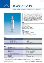
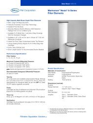
Introduction1 Introduction1.1 Applications in TFFTangential Flow Filtration (TFF) is an efficient method for concentrating, desalting, or exchanging buffer solutions ofbiomolecules ranging in volume from several milliliters to thous<strong>and</strong>s of liters. It can be used to fractionate large from smallbiomolecules, depyrogenate buffer solutions, harvest cell suspensions, <strong>and</strong> clarify fermentation broths <strong>and</strong> cell lysate.TFF is utilized to perform various steps on a wide range of applications in the biopharmaceutical industry, such as:• Concentration <strong>and</strong> desalting of solutions of proteins, peptides <strong>and</strong> oligonucleotides• Purification <strong>and</strong> recovery of antibodies or recombinant proteins from cell culture media• Clarification of cell lysate or tissue homogenates• Recovery of products expressed into the media from cell culture• Preparation of samples (concentrate, desalt, or buffer exchange) before or after column chromatography1.2 Tangential Flow Filtration ProcessThe process conditions for using membrane cassettes in a Tangential Flow Filtration system depend on the specificapplication. Important process parameters that must be considered include:• Retentate Flow Rate (Cross Flow Rate)• Transmembrane Pressure• Temperature• Product characteristics (such as concentration, viscosity, <strong>and</strong> additives)Variations in any of these parameters can affect the quality <strong>and</strong> reproducibility of the TFF process.The operating conditions for any TFF process must be established by performing trials, evaluating results, <strong>and</strong> thenmodifying conditions as necessary to achieve the required results.Because tangential flow filtration membrane cassettes <strong>and</strong> assemblies are used in repeated processing modes, proper care<strong>and</strong> use is crucial to ensure reliable <strong>and</strong> reproducible performance from run to run, <strong>and</strong> to maximize the life of themembrane cassettes.This manual contains detailed steps for the proper installation, preparation, cleaning <strong>and</strong> storage of a tangential flowfiltration (TFF) membrane cassette <strong>and</strong> assembly. The procedures include protocols for <strong>Pall</strong>® screen channel, <strong>and</strong>suspended screen channel cassettes with ultrafiltration (UF) or microfiltration (MF) membranes. Some processes mayrequire adaptations to suit the specific requirements of a given system configuration or application, but essential protocolsshould not be omitted.To perform these procedures, it is recommended that the TFF assembly include 3 pressure gauges/transducers <strong>and</strong>2 valves for proper execution of the protocols presented, see Figure 2: Typical TFF Hardware Setup. To include integritytesting capability (highly recommended), additional valves may be required (Figure 16: System Setup for Determining AirIntegrity).1.3 The TFF ProcessThe steps required in a Tangential Flow Filtration process are displayed in Figure 1: The TFF Process. Preconditioning<strong>and</strong> post-use conditioning are covered in Sections 4 <strong>and</strong> 5 of this manual.Information on product process optimization <strong>and</strong> processing can be found in other supporting literature or through <strong>Pall</strong>Life Sciences Technical Support:PN33289PN33213Diafiltration: A Fast Efficient Method for Desalting or Buffer Exchange of Biological SamplesIntroduction to TFF for Laboratory <strong>and</strong> Process Development ApplicationsThe TFF Process Page 1
The TFF ProcessPre-<strong>Use</strong>ConditioningProcessingPost-<strong>Use</strong>ConditioningInstallationSection 2.2OptimizationBuffer FlushSection 5.1DRAFTInitial FlushingSection 4.2SanitizationSection 4.3ConcentrationDiafiltrationClean-in-PlaceSection 5.2FlushingSection 5.3Final FlushingSection 4.4Normalized WaterPermeability (NWP)Section 4.5Integrity TestSection 4.6Product RecoveryNormalized WaterPermeability (NWP)(<strong>Membrane</strong> Recovery)Section 5.4Integrity Test(optional)Section 5.5Buffer ConditioningSection 4.7Figure 1: The TFF ProcessStorageSection 5.6Page 2<strong>Membrane</strong> Cassette <strong>Care</strong> <strong>and</strong> <strong>Use</strong> <strong>Procedures</strong>
Introduction1.4 System Hardware ConfigurationsSystem hardware configurations vary, but should all have key components (Figure 2: Typical TFF Hardware Setup).All TFF systems should have:Feed/Retentate Flow Path• sample/feed reservoir• feed pump• feed <strong>and</strong> retentate pressure gauges or transducers• adjustable retentate valve• connecting pipingPermeate Flow Path• pressure gauge/transducer• valveFigure 2: Typical TFF Hardware Setup1.4.1 OptionsIn addition to the basic configuration, a valve on the feed side may be added to isolate the system for integrity testing or toseparate it from the feed tank. A flow meter is also typically included with larger systems to allow feed or retentate flowrate measurement. A second flow meter may be used on the permeate. Alternatively, the permeate receptacle may beplaced on a balance. The weight of permeate collected can be used to calculate permeate volumes.Temperature sensors may also be located at the feed tank, on the feed line after the pump, <strong>and</strong> on the permeate line.• Measuring temperature right after the pump will indicate if the pump is causing excessive heating <strong>and</strong> possibledenaturing of proteins.• Measuring the temperature in the feed tank will only show gradual heating.• Measuring the temperature of the permeate gives the actual temperature of the fluid passing through themembrane for determining normalized water permeability (NWP).1.4.2 System DesignThe specific type, size <strong>and</strong> location of components in a system can significantly affect the performance <strong>and</strong> cleanability ofthe system (elimination of bioburden). Critical evaluation of the system design <strong>and</strong> components should be performed byqualified design engineers, especially when the system will be used in process development <strong>and</strong> production <strong>and</strong> willrequire appropriate validation. <strong>Pall</strong> process engineers have extensive experience in TFF system design <strong>and</strong> are available tohelp you with your engineering questions.System Hardware Configurations Page 3
System Hardware Configurations1.4.3 Ports <strong>and</strong> Flow RateThe permeate side of most TFF cassette holders have two ports. While these ports in <strong>Pall</strong> TFF holders are internallyconnected through the cassettes, closing off one of the ports can create an internal pressure drop in the cassette at highpermeate flow rates, > 100 LMH (L/m 2 /hr). These high flow rates are frequently encountered when performing waterpermeability measurements on the cassettes. Since the pressure drop is before the permeate pressure gauge/transducer, it isnot measured by the system. This results in a transmembrane pressure (TMP) measurement/calculation (Equation 1:Transmembrane Pressure Calculation) that is in error on the high side resulting in a low calculated value for waterpermeability (Equation 2: Water Permeability Calculation). In applications where the process is controlled by TMP, theresult may be a low process flux rate.Equation 1: Transmembrane Pressure Calculation⎛TMP P feed + P= ------------------------------------------- retentate⎜⎝2⎞⎟⎠–P permeateWaterPermeabilityPermeateFluxRate( LMH)= --------------------------------------------------------------------TMPDRAFTEquation 2: Water Permeability CalculationPage 4<strong>Membrane</strong> Cassette <strong>Care</strong> <strong>and</strong> <strong>Use</strong> <strong>Procedures</strong>
Cassette Installation2 Cassette Installation2.1 First Time <strong>Use</strong> of Cassette Holder / TFF System2.1.1 Flush <strong>and</strong> Clean the SystemBefore using your TFF system for the first time, flush the system (without cassettes installed) to remove any oil <strong>and</strong>particulates from the manufacturing process that could damage the cassette or contaminate your product.<strong>Use</strong> a detergent-based cleaning solution to clean the system. The solution you choose should be chemically compatiblewith the components in your system. Typically detergent cleaning solution concentrations between 0.5 <strong>and</strong> 1.0 percent attemperatures from 25 to 45 °C are used.A flushing gasket or SIP/CIP Plate should be installed in the holder in place of a cassette.You can make a flushing gasket from the silicone gaskets supplied with membrane cassettes. To prepare a flushing gasket,cut the center out of two spare silicone gaskets (also available as spare parts). <strong>Use</strong> the two gaskets in place of one flushinggasket.2.1.2 Making a Flushing GasketIn the generic drawing (Figure 3: Preparing a Flushing Gasket), the dotted line illustrates where to cut the gasket. The cutline should bisect the channel holes while providing about 2 cm (0.75 in.) of space around the outside of the gasket.Figure 3: Preparing a Flushing GasketPurchasing a Flushing GasketFlushing gaskets (also called SIP/CIP plates) are also available for purchase. Not supplied with holders.2.1.3 System Flushing Protocol1. Fill the feed tank with water.2. Direct the retentate <strong>and</strong> permeate lines to drain.3. Open retentate <strong>and</strong> permeate valves4. Pump the water out through both the retentate <strong>and</strong> permeate lines to drain.5. Prepare a sufficient amount of detergent-based solution to fill the system flow path <strong>and</strong> add to feed tank.(You should be able to run the system without drawing air into the pump.)6. Position both the retentate <strong>and</strong> permeate lines to return to the feed tank7. Adjust the pump to provide an aggressive recirculation flow rate. Do not exceed a feed pressure of 0.34 bar (5 psi)Higher pressures can distort the gasket <strong>and</strong> cause leaks.8. Allow the detergent solution to circulate through both the retentate <strong>and</strong> permeate lines for 30 to 60 minutes.9. Drain the system.10. Wash <strong>and</strong> then refill feed tank with waterFirst Time <strong>Use</strong> of Cassette Holder / TFF System Page 5
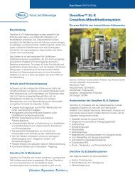
Installing <strong>Membrane</strong> Cassettes11. Flush the system thoroughly to drain using deionized water to remove the detergent solution. If caustic detergentwas used, measure the pH of the waste streams <strong>and</strong> continue flushing until the pH matches that of the influent.12. Drain the system <strong>and</strong> remove the flushing gasket.13. Install the cassettes2.2 Installing <strong>Membrane</strong> Cassettesinto Autotorque (AT) <strong>and</strong> Manual Torque (MT) HoldersFor Maxisette Holders see Section 2.3: Installing Cassettes into Maxisette AT <strong>and</strong> MT Holders on page 72.2.1 Preparation for Loading CassettesProcedure1. Remove the retaining nuts, spacers <strong>and</strong> washers. Separate the sliding end plate from the fixed flow-distributionmanifold:(i) for horizontal units, lift the end plate off the manifold;(ii) for vertical units, slide the end plate away from the manifold about 6 – 9 inches.2. Inspect <strong>and</strong>, if necessary, clean the cassette holder sealing surfaces.Inspect the cassettes <strong>and</strong> gaskets prior to installation for any damage or foreign material which could hamper sealingof the cassettes.DRAFT2.2.2 Installing Cassettes <strong>and</strong> GasketsPreparation: Remove the film cover from the gaskets <strong>and</strong> discard before installationProcedure1. Rinse the silicone gaskets (supplied with the cassettes) with deionized or pharmaceutical grade water. Place a gasketflat against the manifold, aligning the holes in the gasket with the holes in the manifold.2. Place the cassette into the holder against the gasket.Place another gasket flat against the cassette.Ensure the holes in the manifold, gaskets, <strong>and</strong> the cassette line up.3. If your application requires multiple cassettes, continue the same gasket-cassette-gasket pattern, ending with a gasketbetween the last cassette <strong>and</strong> the end plate (Figure 4: Typical Installation of Cassettes <strong>and</strong> Gaskets).Install multiple cassettes with the printed cassette information all facing the same side <strong>and</strong> direction. Try toposition cassettes so that they can be read without having to reopen the holder.4. Place or slide the end plate against the last gasket of the cassette stack:(i) for horizontal units, place the end plate on top of the cassette stack;(ii) for vertical units, slide the end plate against the cassette stack.5. For hardware assemblies that require tie-rod spacers, (Centramate, Maximate, Centrasette LV, Centrasette 5),place the spacers <strong>and</strong> washers on each bolt leaving a minimum of 18 mm (0.75 inches) of thread exposed on therod. Screw the nut on each bolt <strong>and</strong> h<strong>and</strong> tighten firmly.For auto-torque holders, ensure that the piston is fully retracted into the hydraulic cylinder before h<strong>and</strong>tightening the nuts. If it is not, push the piston in by h<strong>and</strong> (with no hydraulic pressure applied to the system).6. Set the clamping force on the cassettes in the holder to the recommended torque for manual torque (MT) holdersor hydraulic pressure for auto-torque (AT) holders according to the instructions found in Section 2.4: How toTorque <strong>Pall</strong> AT <strong>and</strong> MT Cassette Holders on page 9.Two gaskets are supplied with each cassette. Installing the first cassette in a holder requires two gaskets. Installing eachadditional cassette requires only one gasket. In holders where cassettes are installed on each side of the central manifold,two gaskets will be required for each first cassette. Save extra gaskets to replace worn or damaged gaskets.Page 6<strong>Membrane</strong> Cassette <strong>Care</strong> <strong>and</strong> <strong>Use</strong> <strong>Procedures</strong>
Cassette InstallationGaskets lose their resiliency over time. Therefore, it is recommended that you replace gaskets every six months, or morefrequently if a gasket appears to be damaged or you repeatedly open <strong>and</strong> close the holder.2.3 Installing Cassettes into Maxisette AT <strong>and</strong> MT HoldersNote: Maxisette Manual Holders are no longer available2.3.1 Preparation for Loading CassettesProcedure1. Unthread the nuts on each 3/4 inch stainless steel bolt until the end of the bolt is reached to allow as much roomas possible to install the gaskets <strong>and</strong> the cassettes. If the cassettes are to be loaded from the side, remove one centersidebolt from the holder. If the cassettes are to be loaded from the top, no bolts need to be removed.2. Inspect <strong>and</strong>, if necessary, clean the stainless steel sealing surfaces.Inspect the cassettes <strong>and</strong> gaskets prior to installation for any damage or foreign material that could hamper sealingof the cassettes.3. Insert or retract the locating pins so they are extended about 10 cm (4 inches) into the holder.2.3.2 Installing Cassettes <strong>and</strong> GasketsFor Maxisette 50 or 100 Holders, the procedure for Installing Cassettes <strong>and</strong> Gaskets (below) is repeated onboth sides of the center manifold. The number of cassettes to be installed should be distributed equally(e.g., for 6 cassettes, use 3 cassettes per side; for 9 cassettes, use 5 cassettes on one side <strong>and</strong> 4 on the other).On Maxisette 25 holders, cassettes <strong>and</strong> gaskets are installed only on the side of the manifold plate with theports.Procedure1. Remove the film cover from the gaskets <strong>and</strong> discard.2. Rinse the silicone gaskets (supplied with the cassettes) with deionized or pharmaceutical grade water.Place a gasket flat against the movable brace plate using the locating pins to position it accurately.3. Position the cassette on the locating pins <strong>and</strong> push it in toward the brace plate against the gasket. Place another gasketover the locating pins flat against the cassette.The cassettes are not position-sensitive from top to bottom or from end to end.They have identical flow paths regardless of orientation.4. If your application requires multiple cassettes, continue the same gasket/cassette/gasket pattern, ending with a gasketagainst the last cassette. Push the locating pins further into the holder as needed to support the next cassette<strong>and</strong> gasket installed. Make sure the previous gasket has not been wrinkled or damaged.Install multiple cassettes with the printed cassette information facing all on the same side <strong>and</strong> direction, <strong>and</strong>if possible, so that it can be read, without having to reopen the holder.5. After the last cassette <strong>and</strong> gasket have been installed, close the brace plate by pushing it with both h<strong>and</strong>s at the lowestpart of the plate, just adjacent to the rails. This will help eliminate cocking of the plate while closing. Push thelocating pins all the way in <strong>and</strong> leave them in during operation.6. Reinstall the stainless steel bolt <strong>and</strong> nut if it had been previously removed.7. Ensure the pistons are fully retracted into the hydraulic cylinder before h<strong>and</strong> tightening the nuts. If it is not, pushthe piston in by h<strong>and</strong> (no hydraulic pressure on system). Finger-tighten the six nuts down onto the brace plate surface.The holder is now ready to be hydraulically clamped.8. Set the clamping force on the cassettes in the holder to the recommended hydraulic pressure for auto-torque (AT)holders or adjust the torque for manual-torque (MT) holders according to the instructions in section Section 2.4:How to Torque <strong>Pall</strong> AT <strong>and</strong> MT Cassette Holders on page 9Installing Cassettes into Maxisette AT <strong>and</strong> MT Holders Page 7
Installing Cassettes into Maxisette AT <strong>and</strong> MT Holders<strong>Pall</strong> supplies two gaskets with each cassette. Installing the first cassette in a holder requires two gaskets. Installing eachadditional cassette requires only one gasket. In holders where cassettes are installed on each side of the central manifold,two gaskets will be required for each first cassette. Save extra gaskets to replace worn or damaged gaskets.Gaskets lose their resiliency over time. Therefore, <strong>Pall</strong> recommends that you replace gaskets every six months, or morefrequently if a gasket appears to be damaged or you repeatedly open <strong>and</strong> close the holder.DRAFTFigure 4: Typical Installation of Cassettes <strong>and</strong> GasketsPage 8<strong>Membrane</strong> Cassette <strong>Care</strong> <strong>and</strong> <strong>Use</strong> <strong>Procedures</strong>
Cassette InstallationFigure 5: Maxisette 50 Diagram Showing Locating PinsCentrasette LVCentrasette 5Centrasette PCentrasette 10Centramate LVCentramateMaximateMaxisette142 23 464321121Figure 6: <strong>Pall</strong> Manual-Torque Cassette Holders <strong>and</strong> Torquing Sequence352.4 How to Torque <strong>Pall</strong> AT <strong>and</strong> MT Cassette Holders1. Install the membrane cassette <strong>and</strong> gaskets in the holder according to Section 2.2 or 2.3, Installing <strong>Membrane</strong> Cassettes.2. Choose the value at the low end of the hydraulic pressure range for AT assemblies (Table 1: RecommendedHydraulic Pressure Range for <strong>Pall</strong> AT Cassette Holders on page 11) or the torque range for MT holders (Table 2:Recommended Torque Values for <strong>Pall</strong> Manual-torque Cassette Holders on page 12) — unless experience hasestablished a different value for use.3. Compress the holder:How to Torque <strong>Pall</strong> AT <strong>and</strong> MT Cassette Holders Page 9
How to Torque <strong>Pall</strong> AT <strong>and</strong> MT Cassette HoldersAT Assemblies(i) Ensure that the nuts are screwed up against the end plate. They need not be tight.(ii) Close the bypass valve on the hydraulic pump.(iii) Turn on the air supply to the hydraulic pump.(iv) Increase the hydraulic pressure on the hydraulic pump until it reaches the pressure value you determined instep 2.Figure 7: Hydraulic PumpDRAFTMT Assemblies(i) Tighten the nuts firmly by h<strong>and</strong>.(ii) Set the calibrated torque wrench (supplied with the cassette holder) to the torque value you determined instep 2. Refer to the instruction sheet for the wrench for additional calibration details.(iii) Using the torque wrench in the sequence displayed in Figure 6: <strong>Pall</strong> Manual-Torque Cassette Holders <strong>and</strong>Torquing Sequence for your holder, tighten each nut no more than 1/4 turn at a time. For example, tightenthe first nut 1/4 turn, <strong>and</strong> then tighten the next nut in the sequence 1/4 turn.(iv) Stop tightening each nut immediately when the torque wrench “clicks,” or the wrench arm pivots slightly awayfrom the socket indicating that the nut has reached the correct torque. Continue torquing each nut insequence until the torque wrench “clicks” immediately on each nut in sequence. If torqued properly, the nutsshould reach the set torque value at about the same time.The indication that the torque wrench has reached the set value may be very subtle. Therefore, tighten thenuts slowly to prevent exceeding the required torque value.Note: At this point in the installation, the hold-up volume <strong>and</strong> minimum working volume should be determined.See Section 3.3: Hold-up Volume <strong>and</strong> Minimum Working Volume on page 13.4. After cassettes have been installed <strong>and</strong> flushed with water, the system should be inspected for leaks. If liquid isfound leaking from around the cassettes, increase manual torque in 10% increments or the hydraulic pressure inincrements of 3 bar (45 psi). Flush the system with water <strong>and</strong> check again for leaks. Stop increasing the hydraulicpressure when no more leaks are observed.With the system filled with water, pressurize it to exceed the maximum expected process operating pressure byabout 10%.Warning: Do not exceed pressure limits for the cassettes <strong>and</strong> system components or torque <strong>and</strong> hydrauliccompression limits.Check for leaks. If liquid is found leaking from around the cassette, increase manual torque in 10% increments orthe hydraulic pressure in increments of 3 bar (45 psi). Stop increasing when no more leaks are observed.Warning: Do not exceed the maximum recommended torque or hydraulic pressure.If liquid is found leaking from around fittings, check the fittings <strong>and</strong> gaskets. Replace if necessary.Once properly installed <strong>and</strong> compressed in the holder, cassettes can be pre-conditioned <strong>and</strong> used in a process.Page 10<strong>Membrane</strong> Cassette <strong>Care</strong> <strong>and</strong> <strong>Use</strong> <strong>Procedures</strong>
Cassette InstallationA forward flow air integrity test including a system integrity (pressure hold) test should be performed prior to addingproduct to the system (Section 4.6: System <strong>and</strong> <strong>Membrane</strong> Cassette Integrity Test on page 26).5. Periodically check the torque on each bolt for MT holders. Cassettes will compress initially upon installation <strong>and</strong>will require adjustment. Temperature changes to the environment or feed solution may require a torque adjustmentto the holder. AT holders compensate for reduced cassette compression <strong>and</strong> normally do not require periodicadjustment of the hydraulic pressure.Increasing the temperature of the feed solution will cause expansion of the cassettes, causing the clamping force toincrease unless the torque on MT assemblies or hydraulic pressure on AT assemblies is relieved or reduced. It ispossible that the maximum clamping force may be exceeded. If a heated solution will be pumped into the cassettesystem, set the clamping force on both MT <strong>and</strong> AT holders just below the minimum setting prior to adding theheated fluid.When finished using a calibrated torque wrench, adjust the wrench to its minimum force setting for storage.Leaving a torque wrench set to a higher value can cause it to go out of calibration.The torque required to apply the correct clamping force on cassettes depends on the size <strong>and</strong> number of tie rods<strong>and</strong> the surface area over which the force is applied. On <strong>Pall</strong> AT hydraulic closure systems, it also depends on thediameter of the pistons. Values listed in Table 1 <strong>and</strong> Table 2 are recommended for cassettes from <strong>Pall</strong> Life Sciences.When installing cassettes from <strong>Pall</strong> Life Sciences in holders from other manufacturers, contact <strong>Pall</strong> with the specificationsof the holder so that the correct torque or hydraulic pressure can be determined.Excessive compression can permanently damage the cassette.Table 1: Recommended Hydraulic Pressure Range for <strong>Pall</strong> AT Cassette HoldersRecommended Hydraulic Pressure Range for AT HoldersHolder Type (1)No. HydraulicOmega, Alpha <strong>and</strong> Supor® TFF Regen <strong>Membrane</strong> CassettesPistons <strong>Membrane</strong> Cassetteson Holder(psi) (bar) (psi) (bar)Centrasette LV AT 4 500 – 800 34 – 54 400 – 500 27 – 34Centrasette 5 AT 4 500 – 800 34 – 54 400 – 500 27 – 34Centrasette 10 AT 2 1100 – 1600 75 – 110 800 – 1000 54 – 68Centrastak AT 2/level 1100 – 1600 75 – 110 800 – 1000 54 – 68Maxisette AT 6 1400 – 1800 95 – 122 1100 – 1300 75 – 88(1) Recommended hydraulic pressure ranges for these holders with Supor, Omega <strong>and</strong> Alpha cassettes have been lowered from previous versions of thisguide. Changes are based on studies indicating reduced pressures will sufficiently compress cassettes in the holder.How to Torque <strong>Pall</strong> AT <strong>and</strong> MT Cassette Holders Page 11
How to Torque <strong>Pall</strong> AT <strong>and</strong> MT Cassette HoldersTable 2: Recommended Torque Values for <strong>Pall</strong> Manual-torque Cassette HoldersHolder TypeNo. Bolts onHolderRecommended Torque Range for Manual -Torque Cassette Holders (2)Omega, Alpha <strong>and</strong> Supor TFF Regen TFF <strong>Membrane</strong> Cassettes<strong>Membrane</strong> Cassettes(in-lb.) (Nm) (in-lb.) (Nm)Minisette (3) 4 90 – 120 10 – 14 60 – 90 7 – 10Centramate LV 4 50 – 60 6 – 7 40 – 50 5 – 6Centramate 4 60 – 90 7 – 10 40 – 70 5 – 8Centrasette 5,4 300 – 450 35 – 50 150 – 300 17 – 35Centrasette LVCentrasette 10, Centrasette P 2 600 – 900 70 – 100 300 – 600 35 – 70Centrasette 10 4 300 – 450 35 – 50 150 – 300 17 – 35Maximate 4 100 – 160 11 – 8 65 – 120 7 – 14Maxisette 25, Maxisette 50,Maxisette 100 (3) 6 700 – 1050 80 – 120 400 – 500 45 – 56(2) <strong>Pall</strong> membrane cassettes(3) Maxisette MT <strong>and</strong> Minisette Holders are no longer available.DRAFTPage 12<strong>Membrane</strong> Cassette <strong>Care</strong> <strong>and</strong> <strong>Use</strong> <strong>Procedures</strong>
Operating Specifications3 Operating Specifications3.1 Recommended Crossflow Rates for <strong>Pall</strong> <strong>Membrane</strong> CassettesTable 3 lists recommended crossflow flux (CFF) rates for operating <strong>Pall</strong> TFF membrane cassettes. Other parameters suchas TMP <strong>and</strong> temperature can be evaluated at these CFF values.CFF = L/min / ft 2 or m 2 [retentate flow rate /membrane area]The values listed under Processing Mode are recommended for use when processing a sample. Higher flow rates arerecommended for cleaning <strong>and</strong> sanitization (Cleaning Mode).Table 3: Recommended Retentate Crossflow Flux Rates (CFF) for <strong>Pall</strong> TFF CassettesHolder TypeCentramate orCentrasetteMaximate orMaxisetteUnitsMinimum CFFProcessing ModeScreenChannelCassettesSuspendedScreenChannelCassettes(4) Trials must be performed to determine the most effective crossflow rate to use for any specific application.3.2 Operating Pressures, Temperatures <strong>and</strong> pHRecommended CFF (4)Processing ModeScreenChannelCassettesSuspendedScreenChannelCassettesRecommended CFF (4)Cleaning ModeScreenChannelCassettesSuspendedScreenChannelCassettesL/min/m 2 3 8 5 – 8 10 – 20 7 – 12 15 – 30L/min/ft 2 0.3 0.8 0.5 – 0.8 1.0 – 2.0 0.7 – 1.2 1.5 – 3.0L/min/m 2 2 5 4 – 5 7 – 15 6 – 10 10 – 25L/min/ft 2 0.2 0.5 0.4 – 0.5 0.7 – 1.5 0.6 – 1.0 1.0 – 2.5Operating limit specifications for pressure, temperature, <strong>and</strong> pH are listed in Table 4: Cassette Operating Limits ofPressure, Temperature, <strong>and</strong> pH.Table 4: Cassette Operating Limits of Pressure, Temperature, <strong>and</strong> pH<strong>Membrane</strong> Type Temperature Max. PressurepH RangeContinuousat 25 °C (< 8 hr)Cleaning at45 °C (< 4 hr)OmegaAlphaSupor TFF(all formats)-5 to 50 °C 6.8 bar (100 psi) 1 – 14 1 – 144 to 25 °C 3 bar (45 psi) 1 – 14 1 – 1325 to 50 °C 2 bar (30 psi) 1 – 14 1 – 13Regen -5 to 50 °C 5 bar (75 psi) 1 – 13 1 – 133.3 Hold-up Volume <strong>and</strong> Minimum Working VolumeIt is imperative to determine the hold-up volume <strong>and</strong> minimum working volume for your system following installation ofcassettes <strong>and</strong> prior to flushing out the system.Feed/Retentate Hold-up Volume is the total volume, most of which is recoverable, contained within the feed/retentateflow path.Minimum Working Volume is the hold-up volume plus a minimum volume of liquid that must remain in the bottomof the feed tank at the operating flow rate to prevent air from being drawn into the cassette system.Hold-up Volume <strong>and</strong> Minimum Working Volume Page 13
Hold-up Volume <strong>and</strong> Minimum Working VolumeThe minimum working volume limits the maximum concentration factor achievable. It is affected by the crossflowrate. At a higher crossflow rate, a greater liquid volume in the bottom of the feed tank is required to prevent air fromgetting drawn into the pump. Tank design significantly affects the minimum volume required to prevent air from gettinginto the system.Permeate Hold-up Volume is the total volume contained within the permeate flow pathNon-Recoverable Volume is the volume remaining in the Feed/Retentate flow path after the flow channel has beenpumped out <strong>and</strong> drained. Optimization of the product recovery step will ensure high product recovery.3.3.1 Determining Feed/Retentate Hold-up VolumeThis procedure assumes the system is dry <strong>and</strong> cassettes have just been installed, <strong>and</strong> that the retentate line is flexible <strong>and</strong>can be directed either to the reservoir or the drain.)1. Add a measured volume of water into the feed reservoir that will be at least three times the expected hold-up volumefor the system. Record the volume. (If insufficient volume was used, more can be added later.) <strong>Use</strong> the followingtable as a guide.Table 5: Required Volumes for determining Feed/Retentate Hold-up VolumeSystem Approximate volume to add (5)DRAFT2. Close the permeate valve.CentramateMaximateCentrasetteMaxisette300 – 500 mL400 – 600 mL(5) Actual volume will depend on tubing / piping diameter <strong>and</strong> lengths, as well as amount of membrane area installed.Note: For bench-top systems with flexible hoses on the feed <strong>and</strong> retentate lines, add a measured volume of water toa graduated cylinder <strong>and</strong> place the ends of the feed <strong>and</strong> retentate tubing into the cylinder.3. Open the retentate valve completely.4. Start the pump <strong>and</strong> circulate the water through the system until no air bubbles exit the retentate line. (Adjust flowrate so feed pressure is about 0.3 bar (5 psi). If the reservoir or graduated cylinder is completely drained, add anadditional measured volume of water so that residual liquid is left in the reservoir or cylinder when circulated5a. If the liquid was initially poured into the feed reservoir, put the retentate line into a graduated cylinder, leaving thefeed line in the feed reservoir, <strong>and</strong> slowly pump out the water just until the level reaches the very bottom of the reservoir.Do not allow air to be drawn into the feed line.5b. If a graduated cylinder was initially used as the reservoir, carefully remove the feed <strong>and</strong> retentate lines from thegraduated cylinder. Hold up the ends so that water doesn’t run out. If the tubing is not completely filled with water,use a little water from the cylinder to fill them back up.6. Record the volume in the graduated cylinder (B).The difference between the starting volume, plus any volume added (A), <strong>and</strong> the volume in the graduated cylinder (B) isthe feed/retentate hold-up volume (C), (Table 6: Feed/Retentate Hold-up Volume).Table 6: Feed/Retentate Hold-up Volume1 – 3 L5 – 15 LTotal Volume Added A ________________ mL ARemaining Volume In Cylinder B – ________________ mL BFeed/retentate Hold-up Volume (A - B) = ________________ mL CPage 14<strong>Membrane</strong> Cassette <strong>Care</strong> <strong>and</strong> <strong>Use</strong> <strong>Procedures</strong>
Operating Specifications3.3.2 Determining Permeate Hold-up VolumeProcedure1. Add the volume collected in the graduated cylinder to the feed reservoir (or leave in the graduated cylinder if it wasused as a reservoir). If the volume collected (B) was not at least double the retentate hold-up volume (C), add anadditional measured volume to the reservoir or cylinder to increase the total volume in the system to more than 3hold-up volumes.2. Open the retentate <strong>and</strong> permeate valves3. Direct the feed, retentate <strong>and</strong> permeate lines into the feed reservoir or graduated cylinder.4. Start the pump <strong>and</strong> circulate the water for a few minutes through the system until no more air bubbles are seenexiting from the retentate or permeate line. (Adjust the flow rate so feed pressure is 1– 2 bar (15 – 30 psi). Restrictthe retentate valve if necessary.5. If the liquid was initially poured into the feed reservoir, put the retentate line into a graduated cylinder, close thepermeate valve, <strong>and</strong> slowly pump out the water just until the level reaches the very bottom of the reservoir.If a graduated cylinder was initially used as the reservoir, carefully remove the feed, retentate, <strong>and</strong> permeate linesfrom the graduated cylinder. Hold up the ends, so that water doesn’t run out. If the tubing is not completely filledwith water, use a little water from the cylinder to refill them.6. Record the volume remaining in the cylinder (D).The difference between the total volume added (A*) <strong>and</strong> the volume remaining in the cylinder (D) is the total systemhold-up volume (feed/retentate <strong>and</strong> permeate). Subtract the feed/retentate hold-up volume (C) to get the permeate holdupvolume (F), Table 7: Total System Hold-up Volume.Table 7: Total System Hold-up VolumeTotal Volume Added A* (6) ________________ mL A*Remaining Volume InGraduated CylinderD - ________________ mL DTotal System Hold-up Volume(feed/retentate/permeate)(A* - D) = ________________mL EFeed/retentate Hold-up Volume(from Table 6 on page 14)C - ________________ mL CPermeate Hold-up Volume (E - C) = ________________ mL F(6) A* = initial volume of water added (A — from Table 6) plus any addition volume added from Section 3.3.2 in Step 1.3.3.3 Determining the Non-Recoverable VolumeProcedure1. If the liquid was initially poured into the feed reservoir, close the permeate valve, then put the retentate line intothe graduated cylinder <strong>and</strong> slowly pump out the remaining water in the system (combining with the volume collectedfrom the previous step), allowing air to purge out the lines.If a graduated cylinder was initially used as the reservoir, close the permeate valve, then carefully remove the feedline leaving the retentate <strong>and</strong> permeate lines in the cylinder <strong>and</strong> slowly pump out the remaining water in the system,allowing air to purge out the lines.2. <strong>Care</strong>fully remove the permeate line from the graduated cylinder.3. Hold the end up <strong>and</strong> fill the line with water from the cylinder.4. Record the total volume in the graduated cylinder (G).Hold-up Volume <strong>and</strong> Minimum Working Volume Page 15
Hold-up Volume <strong>and</strong> Minimum Working Volume5. Subtract the volume in the graduated cylinder (G) plus the permeate hold-up volume (F) from the total volumeadded (A*).The difference between the total volume added <strong>and</strong> the volume in the graduated cylinder plus the permeate hold-upvolume is the Non-Recoverable Volume (X) (Table 8: Non-Recoverable Volume).Table 8: Non-Recoverable VolumeTotal Volume Added A* (7) ________________ mL A*Volume in Graduated Cylinder G – ________________ mL GPermeate Hold-up Volume F – ________________ mL FNon-recoverable Volume, Feed/RetentateA*- (G + F) = _________________mL X(7) A* = initialDRAFTvolume of water added (A — from Table 6) plus any addition volume added from Section 3.3.2 in Step 1.3.3.4 Determining the System Minimum Working VolumeNote: For this measurement, the actual feed reservoir must be used. This procedure may be performed after thecassettes have been sanitized.Procedure1. Add a volume of water to the feed reservoir equal to at least 4 system hold-up volumes.2. Open the retentate <strong>and</strong> permeate valves. Direct retentate <strong>and</strong> permeate lines into the feed reservoir.3. Adjust the pump to deliver the retentate flow rate that will be used in the process <strong>and</strong> circulate the water for a fewminutes through the system till no more air bubbles are seen exiting from the permeate line.For systems with MF membranes, adjust the permeate valve to give a flux rate in the expected range for processing.If necessary, add additional water to the reservoir to prevent air from being pulled into the feed line.4. Direct the retentate line to drain <strong>and</strong> pump out water just until air is about to be pulled into the feed line. Thenreturn the line to the feed reservoir. If air is pulled in, add just enough water to the reservoir, so no air gets drawninto the lines at the required flow rate.5. Stop the pump.6. Close the permeate valve.7. Remove <strong>and</strong> hold the permeate line up.8. Direct the retentate line to a graduated cylinder <strong>and</strong> slowly pump out the remaining water in the system, allowingair to purge out the lines.9. Fill the permeate line with water from the cylinder.10. Record the volume collected in the graduated cylinder.To determine the Minimum Working Volume, add the Non-Recoverable volume (X) to the Volume Collected in thegraduated cylinder (Y).Table 9: Minimum Working VolumeVolume in Graduated Cylinder Y ________________ mL YNon-recoverable Volume from Table 8 X + ________________ mL XMinimum Working Volume X + Y = _________________mL ZPage 16<strong>Membrane</strong> Cassette <strong>Care</strong> <strong>and</strong> <strong>Use</strong> <strong>Procedures</strong>
Preconditioning Cassettes <strong>and</strong> System4 Preconditioning Cassettes <strong>and</strong> SystemBefore processing product, several steps must be performed (Figure 8: Steps for Preconditioning TFF Cassettes) to assurethat the cassettes are properly installed in the holder <strong>and</strong> fit-for-use to prevent possible sample loss or contamination fromstorage agents. This preconditioning process consists of six steps:Install CassettesDetermining Hold-upVolumeWFI FlushSanitizeWFI FlushDetermineNWPIntegrity TestBufferConditionStep123456Optimization orProcessing ModeFigure 8: Steps for Preconditioning TFF CassettesThe combination of steps 1-3 are required to assure that the storage agents have been effectively <strong>and</strong>sufficiently removed.Step 1 WFI Flush, quickly removes the bulk of the storage agent, so only small quantities of water are required inthis step.Step 2 is designed to reduce or eliminate bioburden from the cassette <strong>and</strong> to extract most of the remaining storageagents.Step 3 flushes out the sanitizing agent <strong>and</strong> reduces extractables to acceptable levels. Flushing volumes must bedetermined by the user for the specific application.The combination of steps 4 <strong>and</strong> 5 establish the fitness of the cassette for use or reuse.Step 4 measurement of Normalized Water Permeability (NWP) is required to establish a pre-use baseline valueagainst which the cassette can be measured following its use in a process <strong>and</strong> subsequent cleaning.Comparing the initial NWP to the NWP value measured after cleaning is a way to establish the effectivenessof the cleaning process.Step 5 establishes the integrity of the cassettes <strong>and</strong> system against leaks <strong>and</strong> possible product loss.Step 6 buffer conditioning, prepares the wetted surfaces of the system as well as the membrane in the cassettebefore the addition of process fluid by removing trapped air from the system <strong>and</strong> equilibrating the system inthe process buffer to reduce the risk of product precipitation or denaturation. It also equilibrates the systemtemperature to the product temperature.Details of each step are presented in the following sections.Warning: Exceeding the maximum operating pressure for the cassette can permanently damage the cassette.4.1 Using a Cassette for the First TimeFirst time use of new membrane cassettes requires the removal of the storage agents (such as glycerin <strong>and</strong> sodium azide, orsodium hydroxide) from the cassettes. A material safety data sheet with important information about the preservativeagents is included with each cassette.Using a Cassette for the First Time Page 17
Initial Flushing of the Cassette <strong>and</strong> Assembly (WFI Flush)The volume of flushing agent <strong>and</strong> flushing time to achieve the required minimum level of extractables may be greater forfirst time use of cassettes compared to subsequent use <strong>and</strong> will depend on the storage agents, membrane porosity <strong>and</strong>temperature of flushing solution.The procedures outlined in Sections 4.2, 4.3, <strong>and</strong> 4.4 are designed to efficiently <strong>and</strong> effectively remove these agents butmay need to be modified to meet your specific requirements for trace level contaminants.4.2 Initial Flushing of the Cassette <strong>and</strong> Assembly (WFI Flush)Flush the cassette <strong>and</strong> hardware assembly with pharmaceutical-grade water. <strong>Use</strong> of a lower quality water toflush the system may introduce inorganic impurities that could affect membrane performance <strong>and</strong> productrecoveries.Water Quality for flushing:WFI (water for injection) at 25 – 45 °C or0.2 μm filtered DI water at 25 – 45 °CVolume Required: 10 - 40 L / m 2 (1 – 4 L/ft 2 )4.2.1 Flush the Feed/Retentate <strong>and</strong> Permeate Line to WasteDRAFTDirect the retentate <strong>and</strong> permeate line to waste.Figure 9: System Setup for FlushingProcedure1. Fill the feed reservoir with water (or attach feed line to water supply).2. Open the retentate <strong>and</strong> permeate valve.3. Adjust the pump to deliver a flow rate of 5 – 10 L/min/m 2 (0.5 – 1 L/min/ft 2 ).Do not exceed a feed pressure of 2 bar (30 psi).If necessary, restrict permeate valve so at least 50% of flow is out the retentate line.4. Pass 5 – 20 L/m 2 (0.5 – 2 L/ft 2 ) through the retentate to waste.Measure the volume passing through the permeate as well as retentate.5. Stop the pump.4.2.2 Flush the Permeate Line to Waste1. Close retentate valve. Open permeate valve.2. Adjust the pump to deliver a permeate flow rate of 5 L/min/m 2 (0.5 L/min/ft 2 ) or until the feed pressure equals2 bar (30 psi).Page 18<strong>Membrane</strong> Cassette <strong>Care</strong> <strong>and</strong> <strong>Use</strong> <strong>Procedures</strong>
Preconditioning Cassettes <strong>and</strong> System3. Pass 5 – 20 L/m 2 (0.5 – 2 L/ft 2 ) through the permeate.The permeate volume collected from the steps detailed in Section 4.2.1 can be added in considering the total volumeflushed through the permeate.4.3 Sanitizing <strong>and</strong> Depyrogenating the Cassette <strong>and</strong> AssemblyThe following agents <strong>and</strong> conditions are recommended for sanitizing the specific <strong>Pall</strong> membrane types listed:Volume Required:5 – 20 L/m 2 (0.5 – 2 L/ft 2 )<strong>Membrane</strong>s:Omega, Alpha, <strong>and</strong> Supor TFF membranesSanitizing <strong>and</strong> Depyrogenating Solutions:0.1 – 0.5 N NaOH at 35 – 45 °C0.1 – 0.5 N NaOH + 200 – 400 ppm NaOCl at 35 – 45 °C10 – 50 ppm NaOCl (pH 6 – 8) at 25 – 45 °CFor cassettes that may have been subjected to high levels of endotoxin, the use of an acid solution may be required as analternative or additional procedure to the caustic processing step listed above:0.1 N Acetic Acid (HAc) at 25 – 45 °C0.1 N Phosphoric Acid (H 3 P0 4 ) at 25 – 45 °C<strong>Membrane</strong>:RegenSanitizing <strong>and</strong> Depyrogenating Solutions:0.1 N NaOH at 25 – 45 °C0.1 – 0.5 N HAc or 0.1 N H 3 PO 4 at 25 – 45 °CWarning: Many solutions recommended for sanitizing <strong>and</strong> depyrogenation may be corrosive <strong>and</strong> or hazardous. Ensureproper safety procedures are followed while h<strong>and</strong>ling, mixing <strong>and</strong> preparing these reagents.4.3.1 Add Sanitizing SolutionFigure 10: System Setup for Adding Sanitizing FluidSanitizing <strong>and</strong> Depyrogenating the Cassette <strong>and</strong> Assembly Page 19
Sanitizing <strong>and</strong> Depyrogenating the Cassette <strong>and</strong> AssemblyProcedure1. Drain the system <strong>and</strong> reservoir.2. Fill the reservoir with sanitizing solution3. Open the permeate <strong>and</strong> retentate valves.4. With the retentate <strong>and</strong> permeate line directed to waste, start the pump <strong>and</strong> run a small volume of sanitizingsolution through the system to waste (flushing with one or two system hold-up volumes is usually sufficient).It may be necessary to partially close the retentate valve to force liquid through the permeate.5. Stop the pump.6. Return the retentate <strong>and</strong> permeate lines to the feed reservoir.4.3.2 Add <strong>and</strong> Recirculate Sanitizing SolutionDRAFTFigure 11: Set-up For Circulating Sanitizing FluidProcedure1. For screen channel cassettes, open the retentate valve <strong>and</strong> close the permeate valve completely. Adjust the pumpspeed to give a retentate flow rate in the range 1 – 1.5 times the recommended process CFF rate in Table 3. Do notexceed a feed pressure of 2.8 bar (40 psi).For suspended screen channel cassettes, keep the permeate valve open. Then adjust the pump speed to give a retentateflow rate in the range 1 – 1.5 times the recommended process CFF rate in Table 3. If the permeate flow rate issignificantly greater than the retentate flow rate, reduce the pump speed, then adjust the permeate valve until theretentate <strong>and</strong> permeate flow rates are approximately equal, then readjust the retentate flow rate.With suspended screen cassettes, the permeate pressure should not exceed the retentate pressure. If necessary,restrict the retentate valve to maintain a positive pressure at the retentate <strong>and</strong> adjust other parameters asrequired to achieve desired results.2. Run for 30 – 60 minutes.The effectiveness of this sanitization procedure to reduce or eliminate bioburden will depend on the nature<strong>and</strong> level of the contamination. The user must evaluate <strong>and</strong> validate the effectiveness of the process withrespect to time <strong>and</strong> temperature <strong>and</strong> the effectiveness of the sanitizing agent for their process.With process systems, it may be necessary to keep the permeate valve open with screen channel cassettes toassure effective sanitization. Process systems often have multiple flow paths that must be flushed with sanitizingsolution in the proper sequence in order to assure effective sanitization. It is up to the user to determinethe appropriate procedure for their system.Page 20<strong>Membrane</strong> Cassette <strong>Care</strong> <strong>and</strong> <strong>Use</strong> <strong>Procedures</strong>
Preconditioning Cassettes <strong>and</strong> System4.4 Flushing the Cassette <strong>and</strong> Assembly after SanitizationWater Quality:WFI at 25 – 45 °C or0.2 μm filtered DI water at 25 – 45 °CVolume Required40 L/ m 2 (4 L/ft 2 ) minimumThe actual volume of water required will depend on a number of factors including:Whether the product is in concentrate or permeate — If the product is in the permeate, a greater volume of waterwill be required to reduce the permeate TOC (total organic carbon) to acceptable levels compared to the retentate.<strong>Membrane</strong> type <strong>and</strong> pore size — Small pore UF membranes (30 kDa) require significantly greater volumes than MF<strong>and</strong> open pore UF membranesFlushing water temperature — Increased temperature reduces required volume.Retentate / Permeate flow rates — Lower flow rates reduce required volumeStorage agent — High viscosity agents will extract slowerMinimum acceptable level of extractables <strong>and</strong> method of detection — such as TOC (total organic carbon),NVR (non-volatile residue), UV (ultraviolet adsorption), conductivity.A flushing study may be required to determine the appropriate volumes to use for your application.4.4.1 Flush the Retentate <strong>and</strong> Permeate Line to WasteDirect the Retentate <strong>and</strong> Permeate lines to WasteFigure 12: System Setup for FlushingProcedure1. Drain, wash <strong>and</strong> refill feed reservoir with water (or attach feed line to water supply).2. Open the retentate <strong>and</strong> permeate valve.3. Adjust the pump to deliver a flow rate of 5 – 10 L/min/m 2 (0.5 – 1 L/min/ft 2 ). Do not exceed a feed pressure of2 bar (30 psi). If necessary, restrict permeate valve so at least 50% of flow is out the retentate line.4. Pass 10 – 20 L/m 2 (1 – 2 L/ft 2 ) through the retentate to waste.5. Stop the pumpFlushing the Cassette <strong>and</strong> Assembly after Sanitization Page 21
Flushing the Cassette <strong>and</strong> Assembly after Sanitization4.4.2 Flush the Permeate Line to WasteProcedure1. Close the retentate valve. Open the permeate valve2. Adjust the pump to deliver a permeate flow rate of 5 L/min/m 2 (0.5 L/min/ft 2 ) or until the feed pressure equals2 bar (30 psi).3. Open the retentate valve until the retentate flow rate is 5 – 10% of the permeate flow rate.4. Run until a minimum of 20 L/m 2 (2 L/ft 2 ) is flushed through the permeate or until the pH <strong>and</strong>/or TOC hasreached an acceptable value — normally close or equal to the pH/TOC of the incoming water.The previous flushing procedure is effective in removing sanitizing solution <strong>and</strong> remaining extractablesfrom the system, but may require a significant quantity of water.The addition of one or more recirculation steps through both retentate <strong>and</strong> permeate can reduce the totalvolume of water needed to achieve the required pH, TOC or extractable levels. A typical recirculation procedureis described in Section 4.4.3: Recirculation Procedure to Reduce pH, TOC <strong>and</strong> Extractables(optional) on page 22.4.4.3 Recirculation Procedure to Reduce pH, TOC <strong>and</strong> Extractables (optional)DRAFTProcedure1. Set up the system for flushing to waste (Figure 9: System Setup for Flushing on page 18).2. Perform steps 4.4.1 <strong>and</strong> 4.4.2 using minimum volumes of water for initial flush.3. Set up the system for recirculation.Figure 13: System Recirculation Setup4. Add 5 – 10 L/m 2 (0.5 – 1 L/ft 2 ) to reservoir (a smaller volume/ft 2 is acceptable for larger systems).5. Open the retentate <strong>and</strong> permeate valves.6. Adjust the pump to deliver a flow rate in the processing range for the type of cassette used (Table 3: RecommendedRetentate Crossflow Flux Rates (CFF) for <strong>Pall</strong> TFF Cassettes on page 13).7. Adjust the retentate valve (or permeate valve), so that the permeate flow rate is approximately equal to the retentateflow rate. Do not exceed a feed pressure of 2 bar (30 psi). Readjust the pump speed to deliver the recommendedretentate flow rate or until the feed pressure reaches 2 bar (30 psi).8. Circulate fluid for 30 – 60 minutes.9. Perform steps 4.4.1 <strong>and</strong> 4.4.2 using minimum volumes of water for flush. Take samples of retentate <strong>and</strong> permeatefrom the effluent at end of the flush <strong>and</strong> assay. If pH, TOC, extractables levels are not acceptable, repeat steps 3 to9 until acceptable levels have been obtained.Page 22<strong>Membrane</strong> Cassette <strong>Care</strong> <strong>and</strong> <strong>Use</strong> <strong>Procedures</strong>
Preconditioning Cassettes <strong>and</strong> System4.5 Determine Normalized Water Permeability (NWP 20 °C ) for CassettesThe initial NWP 20 °C of the membrane cassette is essential to calculate because it is used as the basis for determiningmembrane recovery (i.e., how effectively the membrane was cleaned back to its original state).This procedure must be performed with all new cassettes after steps 4.2 through 4.4 are completed.Water quality should be Water for Injection (WFI) or minimally 0.2 μm filtered DI water.All calculated water permeability rates are normalized to a temperature of 20 °C by applying a temperature correctionfactor (TCF 20 °C ) given in Table 11: Temperature Correction Factors (TCF) for Normalizing Water Permeability.The procedure recommended for performing NWP is with the retentate valve closed (Dead-end Method). This will applya uniform pressure profile across the pathlength of the cassette.NWP should be measured on the cassette after sanitization/flushing (Section 4.3: Sanitizing <strong>and</strong> Depyrogenating theCassette <strong>and</strong> Assembly on page 19) <strong>and</strong> then again after cleaning <strong>and</strong> flushing (Section 5.3: Flush Cleaning Agent fromCassettes <strong>and</strong> Assembly on page 34). An example for determining NWP is shown in Section 4.5.4: An Example of How toDetermine <strong>Membrane</strong> Water Permeability on page 25.Note: If the cleaning protocol for the process uses harsher conditions (such as higher concentration, highertemperature, or a different cleaning agent) than the sanitization procedure, then it is recommended that afull cleaning protocol <strong>and</strong> flushing be performed prior to performing the initial NWP 20 °C .4.5.1 Remove Air from Cassette <strong>and</strong> SystemIt is important to completely remove air from the feed channels to wet out the membrane before determiningNWP 20 °C . Both permeate ports should be open for determining NWP 20 °C . Closing one port can cause asignificant error in TMP measurement due to internal pressure drops, especially with UF membranes > 100kDa or MF membranes.Direct the retentate <strong>and</strong> permeate lines back tothe feed reservoir to minimize the volume ofwater needed.Figure 14: System Setup for Determining <strong>Membrane</strong> Water PermeabilityProcedure1. Check the water level in the reservoir <strong>and</strong> refill if necessary.2. Open the permeate <strong>and</strong> retentate valve completely.3. Adjust the pump speed to deliver the recommended crossflow flux. Refer to Table 3: Recommended RetentateCrossflow Flux Rates (CFF) for <strong>Pall</strong> TFF Cassettes on page 13.(i) With MF, suspended screen channel cassettes, it may be necessary to restrict the permeate valve to achieve thedesired retentate flow rate.Determine Normalized Water Permeability (NWP 20 °C ) for Cassettes Page 23
Determine Normalized Water Permeability (NWP 20 °C ) for Cassettes(ii) If required, set the pump flow rate to the required retentate flow rate.(iii) Adjust the permeate valve till retentate <strong>and</strong> permeate flow rates are approximately equal.(iv) Then readjust the pump speed to deliver the required retentate flow rate.4. Close the retentate valve till the feed pressure increases by 0.7 – 1 bar (10 – 15 psi) or the valve is completely closed,then open immediately.Do not exceed a feed pressure of 3 bar (45 psi).5. Repeat previous step at least three times to remove air.4.5.2 Determine Initial Water Permeability (Dead-end Method)Procedure1. Close the retentate valve <strong>and</strong> open the permeate valve.2. Adjust the feed pump flow rate to generate the desired transmembrane pressure (TMP).Start at the lowest TMP.DRAFTEquation 3: Calculation for Transmembrane Pressure⎛TMP P feed + P= ------------------------------------------- retentate⎜It is recommended that water permeability be measured at three different TMP values.• up to 1 bar (15 psi) for UF membranes ≤ 100 kDa <strong>and</strong>• up to 0.65 bar (10 psi) for UF membranes over 100 kDa <strong>and</strong> for MF membranesFor example, choose the pressures 0.3, 0.65, 1.0 bar (5, 10, 15 psi) for a 10 kDa membrane cassette. Choosethe highest TMP, so that the permeate flow rate does not exceed 150 LMH3. Quickly open <strong>and</strong> then close the retentate valve at least three times to expel any trapped air.4. Measure the permeate flow rate <strong>and</strong> calculate the permeate flux rate in units of LMH (L/m 2 /hr).5. Measure the temperature of the permeate stream.6. Adjust the feed flow rate to the next transmembrane pressure <strong>and</strong> repeat steps 2 – 5.7. Repeat steps 2 – 5 at the highest TMP.8. Plot the water permeate flux rate vs. TMP for the 3 points measured.9. Draw a straight line from the origin that best fits the data points plotted.Note: The plot should be linear for UF membranes. If the points do not fall close to the line, check the pressuregauges for accuracy <strong>and</strong> re-measure.The accuracy <strong>and</strong> reproducibility of measurements are very dependent on the accuracy <strong>and</strong> readability ofthe pressure gauges or transducers used. Be sure to use calibrated equipment that is accurate within the measurementrange.10. From the graph, determine the water permeate flux rate at the transmembrane pressure in Table 10: MeasuringWater Permeability for the membrane type used.Table 10: Measuring Water Permeability<strong>Membrane</strong> MWCO or Pore Size TMPUF 0.65 kDa – 100 kDa 0.7 bar (10 psi)UF >100 kDa 0.3 bar (5 psi)MF 0.1 μm – 1.2 μm 0.1 – 0.2 bar (2 psi)⎝<strong>Use</strong> pressure gauges <strong>and</strong> transmitters with a maximum range of 0 – 2 bar (0 – 30 psi) for accurate, repeatable results.2⎞⎟ –⎠P permeatePage 24<strong>Membrane</strong> Cassette <strong>Care</strong> <strong>and</strong> <strong>Use</strong> <strong>Procedures</strong>
Preconditioning Cassettes <strong>and</strong> SystemWith some MF membrane cassettes, it may not be possible to achieve a TMP above 0.2 bar (3 psi). In thiscase take a single measurement at the highest achievable TMP).11. Calculate the water permeability at the recorded TMP from Equation 4: Water Permeability Calculation.WaterPermeabilityEquation 4: Water Permeability Calculation=PermeateFluxRate( LMH)--------------------------------------------------------------------TMP4.5.3 Normalize the Water Permeability1. Normalize the water permeability to a temperature of 20 °C using Equation 5: Normalized Water PermeabilityCalculation <strong>and</strong> the temperature correction factors (TCF 20 °C ) in Table 11: Temperature Correction Factors(TCF) for Normalizing Water Permeability on page 26.NWP 20°C=PermeateFluxRate( LMH)-------------------------------------------------------------------- × TCF TMP20°CEquation 5: Normalized Water Permeability Calculation4.5.4 An Example of How to Determine <strong>Membrane</strong> Water PermeabilityExample: Water permeate flux rates were measured for a 10 kDa UF membrane cassette at transmembrane pressures of 5,10, <strong>and</strong> 15 psi <strong>and</strong> plotted in Figure 15: Determining <strong>Membrane</strong> Water Permeability. The temperature of the water was16 °C.Determine the initial normalized water permeability (NWP 20 °C ).Figure 15: Determining <strong>Membrane</strong> Water PermeabilityResults:Water Permeability = 110 LMH @ 10 psi = 11.0 LMH/psiNormalized Water Permeability = 11.0 LMH/psi x TCF 20 °C where TCF 20 °C = 1.109(Correcting the water temperature from 16 °C to 20 °C)Normalized Water Permeability (NWP 20 °C ) = 11.0 x 1.109 = 12.2 LMH/psiDetermine Normalized Water Permeability (NWP 20 °C ) for Cassettes Page 25
System <strong>and</strong> <strong>Membrane</strong> Cassette Integrity Test4.6System <strong>and</strong> <strong>Membrane</strong> Cassette Integrity TestTable 11: Temperature Correction Factors (TCF) for Normalizing Water PermeabilityTemperature Correction Factors (TCF 20 °C )T °C TCF 20 °C T °C TCF 20 °C T°C TCF 20 °C T °C TCF 20 °C T°C TCF 20 °C11 1.27 21 0.98 31 0.78 41 0.6412 1.24 22 0.95 32 0.76 42 0.6313 1.20 23 0.93 33 0.75 43 0.624 1.57 14 1.17 24 0.91 34 0.73 44 0.615 1.52 15 1.14 25 0.89 35 0.72 45 0.606 1.47 16 1.11 26 0.87 36 0.70 46 0.597 1.43 17 1.08 27 0.85 37 0.69 47 0.588 1.39 18 1.05 28 0.83 38 0.68 48 0.579 1.35 19 1.03 29 0.81 39 0.66 49 0.5610 1.31 20 1.00 30 0.80 40 0.65 50 0.55DRAFTAir diffusion (or forward flow) is a quantitative test that measures the rate of air diffusing through the wetted membrane orseal defects at a given pressure differential. Since the measurements are relative, air diffusion rates can be performed oncassettes wetted with water or buffer solution.Before performing a forward flow air integrity test on a membrane cassette, the membrane must be completelywetted out. Sections 4.2 through 4.4 should be performed before performing the integrity test.If the system temperature will be altered from the current value, it is recommended that buffer conditioning <strong>and</strong>temperature stabilization (Section 4.7) should be performed before the integrity test.Refer to Figure 16: System Setup for Determining Air Integrity for the setup with the <strong>Pall</strong>tronic Flow Star IntegrityAnalyzer. This instrument regulates air <strong>and</strong> pressure to perform the forward flow air integrity test. The <strong>Pall</strong>tronic FlowStar Integrity Analyzer measures <strong>and</strong> displays the rate of air that is diffusing through the membrane.There are two important steps to the integrity test protocols:1. System Integrity Test (external test)The System Integrity Test checks the external seals, fittings, plumbing <strong>and</strong> gasket assemblies within the pressurizedfeed /retentate flow path for leaks.2. <strong>Membrane</strong> Cassette Integrity Test (internal test)The <strong>Membrane</strong> Cassette Integrity Test checks the membrane <strong>and</strong> internal seal assemblies within the cassette fordefects.The System Integrity Test is usually performed first. This assures that any airflow measured during the <strong>Membrane</strong>Cassette Integrity Test is not the result of an external leak.Performing a System Integrity Test is recommended but not required. If the <strong>Membrane</strong> Cassette Integrity Test passes, theintegrity of the membranes <strong>and</strong> system is confirmed. However, if the <strong>Membrane</strong> Cassette Integrity Test fails, then theSystem Integrity Test should be performed to confirm that no external leaks contribute to the measured airflow.Page 26<strong>Membrane</strong> Cassette <strong>Care</strong> <strong>and</strong> <strong>Use</strong> <strong>Procedures</strong>
PpPreconditioning Cassettes <strong>and</strong> SystemAirSourceIntegrityTest UnitThe integrity test instrument should beplaced at a level above the TFF system toprevent gravity feed of liquid back into theinstrument.IntegrityInlet ValvePpRetentatePermeateFeedTankPumpFpDrainFeedIntegrityOutletValveFigure 16: System Setup for Determining Air Integrity4.6.1 Drain the System (Feed / Retentate Flow Path)Note: The feed/retentate flow path must be drained of liquid before performing the system or membrane cassetteintegrity test.The procedure for draining the feed retentate flow path will depend on the system configuration. The objective is toremove most of the liquid. It is not necessary to completely remove all liquid.ProcedureThe liquid can be removed by any combination of the following steps:1. Opening the drain <strong>and</strong> vent ports on the system to allow liquid to drain out2. Draining or disconnecting the reservoir <strong>and</strong> then using the feed pump (positive displacement) to pump air into thesystem to displace liquid out through the retentate line3. Using an integrity test air source to pressurize with air to force liquid out through feed/retentate line. Liquid canalso be forced out through the membrane <strong>and</strong> permeate line4.6.2 System Integrity Test (External Test)Procedure1. Connect the integrity test unit to the system.The integrity tester may be connected as shown in Figure 15: System Setup for Determining Air Integrity,or you can disconnect the pump <strong>and</strong> attach the air supply from the integrity analyzer in its place. The integritytester may also be connected to the retentate line if an isolation valve is placed between the feed port<strong>and</strong> pump.2. Close the permeate valve <strong>and</strong> any other valves in the feed <strong>and</strong> retentate flow path as required to allow the system tobe pressurized with air.System <strong>and</strong> <strong>Membrane</strong> Cassette Integrity Test Page 27
System <strong>and</strong> <strong>Membrane</strong> Cassette Integrity Test3. Charge the system to a pressure of 2 bar (30 psi).4. The airflow rate displayed on the integrity test unit will increase at first, then drop off. As the pressure stabilizes to2 bar (30 psi), the air mass flow rate should decrease to zero (as shown in the example given in Figure 17: TypicalMass Air Flow Example Plotted for System <strong>and</strong> <strong>Membrane</strong> Integrity Test on page 29.If the mass flow rate = zero (< 5 sccm for membrane area > 0.1m 2 [1 ft 2 ]), the system integrity has passed, so continuewith step 5.If the mass flow rate levels off above zero (> 5 sccm), go to Section 4.6.4 "Troubleshooting System Integrity Failure"on page 28.On some systems, it may take 15 minutes or longer for airflow to drop to zero, since the air diffuses throughthe membrane to pressurize the permeate side. If there is still airflow (> 5 sccm) after the permeate <strong>and</strong> feed/retentate pressures are equal, a leak is indicated.5. Once the system pressure test has been completed, slowly open the permeate valve to relieve the pressure.6. Slowly open the integrity outlet valve or the retentate valve to reduce the air pressure to zero in the feed/retentatechannels.7. Close the integrity outlet valve or retentate valve.4.6.3 <strong>Membrane</strong> Cassette Integrity Test<strong>Membrane</strong> Type: Omega, Alpha, Supor TFF, RegenDRAFTCassette Format: Centramate, Centrasette, Maximate, MaxisetteChannel Format: Screen, Suspended screen, OpenProcedure1. Set the pressure on the integrity test unit to the value listed in Table 12: Pressure <strong>and</strong> Airflow Specifications for <strong>Pall</strong><strong>Membrane</strong> Cassettes.2. Open the permeate valve.Table 12: Pressure <strong>and</strong> Airflow Specifications for <strong>Pall</strong> <strong>Membrane</strong> Cassettes<strong>Membrane</strong> MWCO or Pore Size Test Pressure Allowable air Forward Flow Rateper unit area of membrane500 kDa <strong>and</strong> lower MWCO 2.0 bar (30 psi) ≤ 1600 sccm/m 2 (≤ 150 sccm/ft 2 )1000 kDa <strong>and</strong> 0.16 μm Omega 0.7 bar (10 psi) ≤ 1076 sccm/m 2 (≤ 100 sccm/ft 2 )Supor TFF, 0.1 – 0.8 μm 0.7 bar (10 psi) ≤ 270 sccm/m 2 (≤ 25 sccm/ft 2 )3. Turn on the air supply from the integrity tester to pressurize the system.4. The air flow rate displayed on the integrity test unit will initially increase as the system pressurizes, then dropbefore levelling off to a constant flow rate. This measured constant mass flow rate is the air forward flow (diffusion)rate (Figure 17: Typical Mass Air Flow Example Plotted for System <strong>and</strong> <strong>Membrane</strong> Integrity Test on page 29).5. If the constant mass flow rate falls below the acceptance specification listed in Table 12 on page 28 (<strong>and</strong> is consistentwith previous measurements), the membrane integrity has passed.If the mass flow rate is above the recommended specification or substantially above previous measurements, go toSection 4.6.5: Troubleshooting <strong>Membrane</strong> Integrity Failure on page 29.4.6.4 Troubleshooting System Integrity FailureProcedure1. If a manual-torque (MT) holder is used, check the torque.If an auto-torque (AT) assembly is used, check to make sure the hydraulic pressure is at the correct setting.2. Check all sanitary clamp connections <strong>and</strong> fitting assemblies to assure they are securely tightened.3. Remove the cassettes <strong>and</strong> rinse with WFI water. Inspect the cassette gaskets <strong>and</strong> the holder contact surfaces forimperfections. If the gaskets look worn or deformed, install new gaskets. Reinstall the cassettes in the holder.4. Repeat the System Integrity Test, Section 4.6.2: System Integrity Test (External Test) on page 27.Page 28<strong>Membrane</strong> Cassette <strong>Care</strong> <strong>and</strong> <strong>Use</strong> <strong>Procedures</strong>
Preconditioning Cassettes <strong>and</strong> System4.6.5 Troubleshooting <strong>Membrane</strong> Integrity FailureProcedure1. If a manual-torque (MT) holder is used, check the torque.If an auto-torque (AT) assembly is used, check to make sure the hydraulic pressure is set correctly.2. Repeat the System Integrity Test.3. Remove the cassettes <strong>and</strong> rinse with WFI. Inspect the cassette gaskets for imperfections.If the gaskets look worn or deformed, install new gaskets. Reinstall the cassettes in the holder.4. Repeat the <strong>Membrane</strong> Cassette Integrity Test (Section 4.6.3: <strong>Membrane</strong> Cassette Integrity Test on page 28).If the cassette still fails an integrity test, contact your local <strong>Pall</strong> representative for assistance.If multiple cassettes are installed <strong>and</strong> the air diffusion rate continues to exceed specification limits, disassemble the stack ofcassettes <strong>and</strong> test the integrity of each cassette individually to determine if integrity failure is specific to a cassette.0External TestAs the system fills with air to the targetedtest pressure, the air flow rate will decreaseto zero (base line). If it does not reach zero,the system has an external leak. Check allfittings <strong>and</strong> valves.Internal <strong>Membrane</strong> TestWhen the permeate valve is open, the airflow rate will rise. Then the flow rate willdecrease to a steady state, which is the trueair diffusion (forward flow) rate.Figure 17: Typical Mass Air Flow Example Plotted for System <strong>and</strong> <strong>Membrane</strong> Integrity Test4.6.6 Integrity Testing Systems with Multiple CassettesTrue integrity can only be validated on individual cassettes. Hence, testing should first be done on each cassette separately.Then the individual cassettes can be installed in the holder <strong>and</strong> tested as a unit. For a stack of cassettes, the air diffusionrate is additive <strong>and</strong> should approximate the sum of the individual cassettes.4.7 Buffer ConditioningBuffer conditioning the membrane cassettes <strong>and</strong> TFF assembly is critical for most biopharmaceutical applications.Buffer conditioning removes trapped air from the membrane cassette <strong>and</strong> system <strong>and</strong> establishes conditions for pH, ionicstrength <strong>and</strong> temperature to match the process sample. This is important to prevent sample precipitation or denaturationwhen it is first introduced into the system.For this operation, use the same buffer that was used to prepare the sample.The buffer must be at the same temperature as the process fluid.<strong>Membrane</strong> cassettes <strong>and</strong> hardware that are subject to substantial temperature changes (> 10 °C) will requirea torque adjustment to be made on the cassette holder after steady state is reached. For example, if the hardwaresurface temperature is 20 – 25 °C <strong>and</strong> fluid is introduced at 4 °C, the torque on a full stack of cassettesmay drop 20 –40% due to contraction of the polymeric elements. In such cases, integrity testing should beperformed after all adjustments have been made.Volume of Buffer Required: 5 – 20 L/m 2 (0.5 – 2 L/ft 2 ). (Less buffer may be required for large process systems.)Buffer Conditioning Page 29
Buffer Conditioning4.7.1 Flush the Retentate <strong>and</strong> Permeate Lines with BufferDirect the retentate <strong>and</strong> permeate lines to waste.Figure 18: Setup for Buffer Conditioning — Initial FlushDRAFTProcedure1. Drain the system <strong>and</strong> feed reservoir, then fill feed reservoir with buffer.2. Open the permeate <strong>and</strong> retentate valves.3. Start the pump <strong>and</strong> increase pump speed until liquid begins to flow through both the retentate <strong>and</strong> permeate lines.If necessary, adjust the retentate valve to force flow through permeate.4. Run for 5 – 10 seconds, then stop.4.7.2 Remove Trapped Air from the Retentate LineDirect the retentate <strong>and</strong> permeate lines to feed reservoirFigure 19: Setup for Buffer Conditioning — RecirculationProcedure1. Set up the system for recirculation.2. Open the retentate <strong>and</strong> permeate valves.3. Adjust the pump speed to give the recommended crossflow flux. Refer to Table 3: Recommended Retentate CrossflowFlux Rates (CFF) for <strong>Pall</strong> TFF Cassettes on page 13.Page 30<strong>Membrane</strong> Cassette <strong>Care</strong> <strong>and</strong> <strong>Use</strong> <strong>Procedures</strong>
Preconditioning Cassettes <strong>and</strong> SystemWith MF, suspended screen channel cassettes, it may be necessary to restrict the permeate valve to achievethe desired retentate flow rate. If required, set the pump flow rate to the required retentate flow rate. Adjustthe permeate valve until the retentate <strong>and</strong> permeate flow rates are approximately equal. Then readjust thepump speed to give the required retentate flow rate.4. Close the retentate valve until the feed pressure increases by 0.7 – 1 bar (10 – 15 psi) or valve is completely closed,then open immediately.Do not exceed a feed pressure of 3 bar (45 psi).5. Repeat this step at least three times to remove air.6. If necessary, adjust the pump flow rate to maintain a feed pressure of 1 – 2 bar (15 – 30 psi) for UF membranes<strong>and</strong> 0.2 – 0.7 bar (3 – 10 psi) for MF membranes.7. Recirculate fluid for 10 – 15 minutes if conditioning for pH <strong>and</strong> ionic stability at ambient temperature. For equilibratingtemperature between the hardware <strong>and</strong> fluid stream, continue until the temperature has stabilized.8. Check the torque on the cassette holder (not required for auto-torque (AT) systems).9. Remove the excess buffer from the feed vessel. Keep all piping, tubing, <strong>and</strong> cassette assembly to <strong>and</strong> from the feedvessel flooded with buffer to prevent air from entering the system.It is necessary to determine the system hold-up volume in the feed/retentate flow path. This volume willdilute the process fluid <strong>and</strong> must be considered when calculating concentration factor. Refer to Section 3.3:Hold-up Volume <strong>and</strong> Minimum Working Volume on page 13.Buffer Conditioning Page 31
Flushing Cassettes after <strong>Use</strong>5 Post-use Treatment of Cassettes <strong>and</strong> SystemOnce the TFF Process has been completed <strong>and</strong> the product recovered, the membrane cassettes can be cleaned <strong>and</strong> reused.There are several steps that must be followed to remove remaining contaminants <strong>and</strong> return the cassettes to initialcondition.Optimization orProcessing ModePost-use IntegrityTest (optional)Buffer orWFI FlushClean-in-PlaceWFI FlushDetermine NWP <strong>and</strong><strong>Membrane</strong> RecoveryCassetteStorageStep12345Figure 20: SequenceDRAFTof Steps for Post-use Treatment of TFF CassettesThe cleaning process should also be documented <strong>and</strong> validated if cassettes will be reused in production of abiopharmaceutical product. This flushing <strong>and</strong> cleaning process takes considerable time <strong>and</strong> uses substantial quantities ofwater <strong>and</strong> cleaning agent. It may be worth evaluating the economics of cleaning <strong>and</strong> validation for reuse compared todiscarding cassettes after a single use.5.1 Flushing Cassettes after <strong>Use</strong>Following a TFF process, the product, if in the concentrate, would have likely been recovered by displacement with bufferfollowed by a recirculation <strong>and</strong> flushing with a small additional volume of buffer. In this case, it may not be necessary toflush the cassette before adding cleaning solution.If the product was in the permeate, the concentrate should be flushed from the cassette using water or buffer prior tointroducing cleaning solution.5.1.1 Flush the Feed / Retentate Line to WasteVolume Required 10 L/m 2 (1.0 L/ft 2 )Direct the Retentate <strong>and</strong> Permeate Lines to WasteFigure 21: System Setup for Flushing to WastePage 32<strong>Membrane</strong> Cassette <strong>Care</strong> <strong>and</strong> <strong>Use</strong> <strong>Procedures</strong>
Post-use Treatment of Cassettes <strong>and</strong> System1. Drain <strong>and</strong> refill the feed reservoir with 10 – 40 L/m 2 (1 – 4 L/ft 2 ) buffer or WFI.2. Open the retentate <strong>and</strong> permeate valves.3. Adjust the pump to deliver a flow rate of 5 – 10 L/min/m 2 (0.5 – 1 L/min/ft 2 ). Do not exceed a feed pressure of2 bar (30 psi). If necessary, restrict the permeate valve, so at least 50% of flow is removed from the retentate line.4. Pass a minimum of 5 – 20 L/m 2 (0.5 – 2 L/ft 2 ) through the retentate line to waste. Measure the volume passingthrough the permeate as well as the retentate.5. Stop the pump.5.1.2 Flush the Permeate Line to Waste1. Close the retentate valve. Open the permeate valve.2. Adjust the pump to deliver a permeate flow rate of 5 L/min/m 2 (0.5 L/min/ft 2 ) or until the feed pressure equals2 bar (30 psi).3. Pass 5 – 20 L/m 2 (0.5 – 2 L/ft 2 ) through the permeate. The volume collected in step 5.1.1 can be added in consideringthe total volume flushed through the permeate.5.2 Cleaning CassettesVolume Required 5 L/m 2 (0.5 L/ft 2 ) minimumRecommended cleaning agents for <strong>Pall</strong> membranes(see Section 6.2: Alternative Cleaning Agents on page 43 for alternatives):<strong>Membrane</strong> Types Omega, Alpha, Supor TFFCleaning Solutions 0.1 – 0.5 N NaOH at 35 – 45 °C0.1 – 0.5 N NaOH + 200 – 400 ppm NaOCl at 35 – 45 °C<strong>Membrane</strong> Type RegenCleaning Solution 0.1 N NaOH at 35 – 45 °CWarning: Many solutions that are recommended for cleaning may be corrosive. Ensure proper safety proceduresare followed while h<strong>and</strong>ling, mixing <strong>and</strong> preparing these reagents.5.2.1 Adding Cleaning Agent to System1. Drain the system <strong>and</strong> reservoir.2. Fill the reservoir with 5 – 20 L/m 2 (0.5 – 2 L/ft 2 ) of cleaning solution.3. Open the permeate <strong>and</strong> retentate valves.4. With the retentate <strong>and</strong> permeate line still directed to waste, start the pump <strong>and</strong> run a small volume of cleaningsolution through the system to waste.Typically flushing with one or two system hold-up volumes is sufficient. It may be necessary to partiallyclose the retentate valve to force liquid through the permeate.5. Stop the pump.6. Return the retentate <strong>and</strong> permeate line back to the feed reservoir.Cleaning Cassettes Page 33
Flush Cleaning Agent from Cassettes <strong>and</strong> Assembly5.2.2 Recirculate Cleaning SolutionReturn the retentate line to the feed reservoir.DRAFTFigure 22: System Setup for Circulating Cleaning Solution1a. For screen channel cassettes, open the retentate valve <strong>and</strong> close the permeate valve completely. Adjust the pumpspeed to give a retentate flow rate in the range of 1 – 1.5 times the recommended process CFF rate in Table 3: RecommendedRetentate Crossflow Flux Rates (CFF) for <strong>Pall</strong> TFF Cassettes on page 13.Do not exceed a feed pressure of 2.8 bar (20 – 40 psi).1b. For suspended screen channel cassettes, keep the permeate valve open. Adjust the pump speed to give a retentateflow rate in the range 1 – 1.5 times the recommended process CFF rate in Table 3: Recommended RetentateCrossflow Flux Rates (CFF) for <strong>Pall</strong> TFF Cassettes on page 13.If the permeate flow rate is significantly greater than the retentate flow rate, reduce the pump speed, then adjust thepermeate valve until the retentate <strong>and</strong> permeate flow rates are approximately equal, then readjust the retentate flowrate.With suspended screen cassettes, the permeate pressure should not exceed the retentate pressure. If necessary,restrict the retentate valve to maintain a positive pressure at the retentate <strong>and</strong> adjust other parameters as required toachieve desired results.2. Run 45 – 60 minutes for cleaning.If the cleaning solution looks dirty after only a few minutes, stop cleaning <strong>and</strong> drain the cleaning solution.Follow steps 5.1.1 <strong>and</strong> 5.1.2 to flush with water through the retentate than the permeate. Add fresh cleaningsolution to the feed reservoir <strong>and</strong> follow the steps in Section 5.2.1: Adding Cleaning Agent to System onpage 33.5.3 Flush Cleaning Agent from Cassettes <strong>and</strong> AssemblyFlush the cassette <strong>and</strong> hardware assembly with either:1. WFI at 25 – 45°C, or2. 0.2 μm filtered DI water at 25 – 45 °CVolume required: 40 L/m 2 (4 L/ft 2 ) minimumTo establish required flushing volumes for a specific application, test the pH <strong>and</strong>/or conductivity of waterfrom the retentate to determine when acceptable conditions have been reached. If the product will be in thepermeate, test the pH <strong>and</strong> conductivity of the permeate.Page 34<strong>Membrane</strong> Cassette <strong>Care</strong> <strong>and</strong> <strong>Use</strong> <strong>Procedures</strong>
Post-use Treatment of Cassettes <strong>and</strong> System5.3.1 Flush the Retentate Line to WasteFigure 23: System Setup for Flushing Cleaning Solution to Waste1. Drain, wash, <strong>and</strong> refill the feed reservoir with water (or attach the feed line to the water supply).2. Open the retentate <strong>and</strong> permeate valve.3. Adjust the pump to deliver a flow rate of 5 – 10 L/min/m 2 (0.5 – 1 L/min/ft 2 ). Do not exceed a feed pressure of2 bar (30 psi). If necessary restrict the permeate valve, so at least 50% of flow is from the retentate line.4. Pass 10 – 20 L/m 2 (1 – 2 L/ft 2 ) through the retentate to waste.5. Stop the pump.5.3.2 Flush the Permeate Line to Waste1. Close the retentate valve.2. Open the permeate valve3. Adjust the pump to deliver a permeate flow rate of 5 L/min/m 2 (0.5 L/min/ft 2 ) or until the feed pressure equals 2bar (30 psi).4. Open the retentate valve until the retentate flow rate is 5 – 10% of the permeate flow rate.5. Run until a minimum of 20 L/m 2 (2 L/ft 2 ) is flushed through the permeate, or until the pH <strong>and</strong>/or TOC hasreached an acceptable value — normally close or equal to the pH/TOC of the incoming water.The addition of one or more recirculation steps through both retentate <strong>and</strong> permeate can be used to reducethe total volume of water needed to achieve the required pH, TOC, or extractable levels. See Section 5.3.3:Recirculation Procedure to Reduce pH, TOC, <strong>and</strong> Extractables (optional) on page 35.5.3.3 Recirculation Procedure to Reduce pH, TOC, <strong>and</strong> Extractables (optional)1. Set up the system for flushing to waste (Figure 23: System Setup for Flushing Cleaning Solution to Waste)2. Perform the steps in sections 5.3.1 <strong>and</strong> 5.3.2 using minimum volumes of water for initial flush.3. Set up the system for recirculation (Figure 24: System Setup for Recirculation).Flush Cleaning Agent from Cassettes <strong>and</strong> Assembly Page 35
Determine <strong>Membrane</strong> Recovery for the CassettesFigure 24: SystemDRAFTSetup for Recirculation4. Add 5 – 10 L/m 2 (0.5 – 1.0 L/ft 2 ) to reservoir (A smaller volume/ft 2 is acceptable for larger systems)5. Open the retentate <strong>and</strong> permeate valves.6. Adjust the pump to deliver a flow rate in the processing range for the cassette type used (Table 3: RecommendedRetentate Crossflow Flux Rates (CFF) for <strong>Pall</strong> TFF Cassettes on page 13).7. Adjust retentate valve (or permeate valve) so permeate flow rate is approximately equal to retentate flow rate. Donot exceed a feed pressure of 2 bar (30 psi). Readjust pump speed to give recommended retentate flow rate or feedpressure reaches 2 bar (30 psi).8. Circulate liquid for 30 – 60 minutes.9. Perform steps 5.3.1 <strong>and</strong> 5.3.2 using minimum volumes of water for flush. Take samples of retentate <strong>and</strong> permeatefrom the effluent at end of flush <strong>and</strong> assay. If the pH, TOC, <strong>and</strong> extractable levels are not acceptable, repeat steps3 to 9 until acceptable levels have been obtained.5.4 Determine <strong>Membrane</strong> Recovery for the Cassettes<strong>Membrane</strong> recovery is a calculation to determine the efficiency of the cleaning performed on the membranes. It comparesthe normalized water permeability (NWP) after cleaning to the initial NWP, measured when the membrane was firstinstalled <strong>and</strong> preconditioned (Section 4.5: Determine Normalized Water Permeability (NWP 20 °C ) for Cassettes onpage 23).Water quality should be Water for Injection (WFI) or, at minimum, 0.2 μm filtered DI water. All water permeability ratesare normalized to a temperature of 20 °C by using a temperature correction factor (TCF 20 °C ) obtained from Table 11:Temperature Correction Factors (TCF) for Normalizing Water Permeability on page 26.5.4.1 Remove Air from Cassette <strong>and</strong> SystemIt is important to completely remove air from the feed channels <strong>and</strong> wet out the membrane before determiningNWP 20 °C .Page 36<strong>Membrane</strong> Cassette <strong>Care</strong> <strong>and</strong> <strong>Use</strong> <strong>Procedures</strong>
Post-use Treatment of Cassettes <strong>and</strong> SystemDirect the retentate <strong>and</strong> permeate lines back to the feed reservoir tominimize the volume of water needed.Figure 25: System Setup For Determining <strong>Membrane</strong> Water PermeabilityBoth permeate ports should be open for determining NWP 20 °C . Closing one port can cause a significant errorin TMP measurement due to internal pressure drops, especially with UF membranes >100 kDa or MFmembranes.1. Check the water level in reservoir <strong>and</strong> refill if necessary.2. Open the permeate <strong>and</strong> retentate valve completely.3. Adjust the pump speed to deliver the recommended crossflow flux. Refer to Table 3: Recommended RetentateCrossflow Flux Rates (CFF) for <strong>Pall</strong> TFF Cassettes on page 13.With MF, suspended screen channel cassettes, it may be necessary to restrict the permeate valve to achieve thedesired retentate flow rate.(i) If required, set the pump flow rate to the required retentate flow rate.(ii) Adjust the permeate valve until the retentate <strong>and</strong> permeate flow rates are approximately equal.(iii) Then readjust the pump speed to give required retentate flow rate.4. Close the retentate valve till the feed pressure increases by 0.7 – 1 bar (10 – 15 psi) or the valve is completelyclosed, then open immediately.Do not exceed a feed pressure of 3 bar (45 psi).5. Repeat the previous step at least three times to remove air.5.4.2 Determine the Water Permeability after CleaningProcedure1. Close the retentate valve <strong>and</strong> open the permeate valve.2. Adjust the feed pump flow rate to generate the desired transmembrane pressure (TMP).Start at the lowest TMP.⎛TMP P feed + P= ------------------------------------------- retentate⎜Equation 6: Calculation for Transmembrane Pressure⎝2⎞⎟⎠– P permeateDetermine <strong>Membrane</strong> Recovery for the Cassettes Page 37
Determine <strong>Membrane</strong> Recovery for the CassettesIt is recommended that water permeability be measured at three different TMP values.• up to 1 bar (15 psi) for UF membranes ≤ 100 kDa <strong>and</strong>• up to 0.65 bar (10 psi) for UF membranes over 100 kDa <strong>and</strong> for MF membranesFor example, choose the pressures 0.3, 0.65, 1.0 bar (5, 10, 15 psi) for a 10 kDa membrane cassette. Choosethe highest TMP, so that the permeate flow rate does not exceed 150 LMH3. Quickly open <strong>and</strong> then close the retentate valve at least three times to expel any trapped air.4. Measure the permeate flow rate <strong>and</strong> calculate the permeate flux rate in units of LMH (L/m 2 /hr).5. Measure the temperature of the permeate stream.6. Adjust the feed flow rate to the next transmembrane pressure <strong>and</strong> repeat steps 2 – 5.7. Repeat steps 2 – 5 at the highest TMP.8. Plot the water permeate flux rate vs. TMP for the 3 points measured.9. Draw a straight line from the origin that best fits the data points plotted.Note: The plot should be linear for UF membranes. If the points do not fall close to the line, check the pressuregauges for accuracy <strong>and</strong> re-measure.The accuracy <strong>and</strong> reproducibility of measurements are very dependent on the accuracy <strong>and</strong> readability ofthe pressure gauges or transducers used. Be sure to use calibrated equipment that is accurate within the measurementrange.DRAFTTable 13: Measuring Water Permeability10. From the graph, determine the water permeate flux rate at the transmembrane pressure in Table 13: MeasuringWater Permeability for the membrane type used.<strong>Membrane</strong> MWCO or Pore Size TMPUF 0.65 kDa – 100 kDa 0.7 bar (10 psi)UF >100 kDa 0.3 bar (5 psi)MF 0.1 μm – 1.2 μm 0.1 – 0.2 bar (2 psi)<strong>Use</strong> pressure gauges <strong>and</strong> transmitters with a maximum range of 0 – 2 bar (0 – 30 psi) for accurate, repeatable results.With some MF membrane cassettes, it may not be possible to achieve a TMP above 0.2 bar (3 psi). In thiscase take a single measurement at the highest achievable TMP).11. Calculate the water permeability at the recorded TMP from Equation 7: Water Permeability Calculation.WaterPermeabilityEquation 7: Water Permeability Calculation=PermeateFluxRate( LMH)--------------------------------------------------------------------TMP5.4.3 Normalize the Water PermeabilityNormalize the water permeability to a temperature of 20 °C using Equation 8: Calculation for Normalized WaterPermeability <strong>and</strong> the temperature correction factor (TCF 20 °C ) in Table 11: Temperature Correction Factors(TCF) for Normalizing Water Permeability on page 26.NWP 20°C=PermeateFluxRate( LMH)-------------------------------------------------------------------- × TCFTMP20°CEquation 8: Calculation for Normalized Water PermeabilityPage 38<strong>Membrane</strong> Cassette <strong>Care</strong> <strong>and</strong> <strong>Use</strong> <strong>Procedures</strong>
Post-use Treatment of Cassettes <strong>and</strong> System5.4.4 Determine the <strong>Membrane</strong> RecoveryCalculate the membrane recovery using Equation 9: Calculation for <strong>Membrane</strong> Recovery.<strong>Membrane</strong>RecoveryNWP aftercleaningNWP initial= -------------------------------------- × 100%Equation 9: Calculation for <strong>Membrane</strong> Recovery5.4.5 Evaluate the Effectiveness of the Cleaning RegimenFor a new process, if membrane recovery is less than 100%, the cleaning regimen should be repeated. This is to determinethat the initial cleaning time at the selected conditions was sufficient, <strong>and</strong> if not, to determine the appropriate number ofcleaning cycles or time required. If membrane recovery has improved after the second cleaning cycle, a third cycle shouldbe performed. When no additional improvement in recovery is achieved, you know the last cycle time had reachedmaximum effect for the conditions used. You may then use one cleaning cycle for the established time or two or morecycles of shorter duration to equal the desired time. Several cycles may be preferred, especially if cleaning is done at anelevated temperature <strong>and</strong> the system cannot maintain temperature of the cleaning fluid.Studies altering conditions, cycle time, temperature, or reagent concentration should be performed to evaluate the mosteffective cleaning protocol for your processTypically, if the membrane recovery is less than 80% after establishing the appropriate cleaning cycle time, then thecleaning agent or process parameters (such as the temperature, <strong>and</strong> crossflow rate) may have to be altered.The effectiveness of the cleaning regimen should be evaluated over at least three process cycles. It is not uncommon tofind an initial drop in membrane recovery (NWP) of 10 – 15% or more after the first process cycle. However, after thisinitial drop, membrane recovery should be fairly consistent from cycle to cycle. A continual decrease in recovery indicatesthat the cleaning regimen may not be effective <strong>and</strong> should be re-evaluated.Note: Between uses, membrane cassettes are typically stored in a caustic solution (0.05 – 0.1 N NaOH). Duringthis time, remaining foulants on the membrane may be degraded <strong>and</strong> removed when the membrane cassettesare flushed prior to the next use. As a result of membrane relaxation <strong>and</strong> additional cleaning duringstorage, it is not unusual for the membrane recovery, measured after storage, to increase relative to the membranerecovery measured immediately after cleaning.5.5 Post-<strong>Use</strong> Air Integrity Test (optional)Post-use air integrity tests are not usually performed on TFF cassettes. There are no requirements, as with sterilizing gradefilters, that the cassette must pass a post-use integrity test. Usually analysis of results, including performing a mass balanceto establish if there is product loss <strong>and</strong> where the loss might be, is sufficient to establish that the system is workingsatisfactorily. If you wish to determine post-use integrity, follow the procedure given in Section 4.6: System <strong>and</strong><strong>Membrane</strong> Cassette Integrity Test on page 26.5.6 Storage of <strong>Membrane</strong> CassettesThe objective for proper storage of the membrane cassettes is to ensure the membranes remain wet <strong>and</strong> prevent microbialgrowth during the time the membrane cassettes are not being used.Compression on cassettes stored in the holder should be reduced during storage. Reduce the torque or hydraulic pressureby 25%. Check that there is no external leaking from around the cassettes.Storage of <strong>Membrane</strong> Cassettes Page 39
Storage of <strong>Membrane</strong> Cassettes5.6.1 Recommended Storage Agents for the <strong>Pall</strong> <strong>Membrane</strong>sRecommended storage agents for <strong>Pall</strong> membranesTable 14: Storage Agents for Omega, Alpha, <strong>and</strong> Supor TFF <strong>Membrane</strong>sTimeSolution< 6 months 0.05 – 0.1 N NaOH (8)> 6 months 15% glycerin + 0.05% sodium azide(8) Cassettes may be stored for periods up to 1 year or longer. However, it is recommended that at 6 months storage, the pH of the storage solution betested to determine if it is sufficiently caustic. Cassettes may be flushed with fresh storage solution at this time.Table 15: Storage Agents for Regen <strong>Membrane</strong>sTimeSolution< 1 month 0.05 N NaOH> 1 month 15% glycerin + 0.05% sodium azideTable 16: Recommended Storage Temperatures for <strong>Use</strong>d CassettesDRAFTIf cassettes will be stored in water, skip Sections 5.6.2 <strong>and</strong> 5.6.3 go to Section 5.6.4: Cassette Storage on page 41.Temperature4 – 15 °C (40 – 60 °F) optimal25 °C (77 °F) maximumDo not freeze.5.6.2 Adding Storage Agent to SystemFigure 26: System Setup for flushing storage agent through systemVolume of Storage Agent Required 5 – 10 L/m 2 (0.5 – 1 L/ft 2 )Procedure1. Drain the system <strong>and</strong> add storage agent to the feed reservoir.2. Open the retentate <strong>and</strong> permeate valves.3. Start the pump <strong>and</strong> increase speed until the flow comes through both the retentate <strong>and</strong> permeate lines. Allow a volumeequivalent to about 2 holdup volumes to pass out of the retentate to wastePage 40<strong>Membrane</strong> Cassette <strong>Care</strong> <strong>and</strong> <strong>Use</strong> <strong>Procedures</strong>
Post-use Treatment of Cassettes <strong>and</strong> System4. Allow a volume equivalent to about 2 holdup volumes to flow from the permeate to waste.If necessary, partially close the retentate valve to increase permeate flow rate.5.6.3 Recirculate Storage SolutionFigure 27: System Setup for Recirculating Storage SolutionProcedure1. Open the retentate valve. Leave permeate valve partially open2. Adjust the pump speed to maintain a feed pressure of 1 – 2 bar (15 – 30 psi) for UF membranes <strong>and</strong> 0.2 – 0.7 bar(3 – 10 psi) for MF membranes.3. Adjust permeate valve so that the permeate flow rate is 5 – 10% of feed flow rate within the specified pressurerange.4. Run for 3 – 5 minutes.5. Stop the pump.5.6.4 Cassette StorageProcedure for Storage in the Holder1. Close the feed, retentate, <strong>and</strong> permeate valves. (The holder <strong>and</strong> cassettes remain flooded with storage agent.)2. Reduce the torque or hydraulic pressure on the holder by 25%.3. Check that there are no external leaks from around the cassettes.4. Increase the torque or hydraulic pressure slightly if it is necessary to stop a leak.Procedure for Storage out of Holder1. Place the cassette into a plastic bag <strong>and</strong> seal. <strong>Use</strong> a separate bag for each cassette.A small amount of storage agent may be added to the bag.2. Place the bag with the cassette into a plastic container with a lid.3. Keep the cassettes in a temperature-controlled room, optimally at a temperature of 4 – 15 °C.Alternatively1. Place the cassettes in a plastic container with an airtight seal.2. Add storage agent to cover the cassettes completely.3. Cover <strong>and</strong> seal the container.4. Keep the container in a temperature-controlled room, optimally at a temperature of 4 – 5 °C.Storage of <strong>Membrane</strong> Cassettes Page 41
<strong>Membrane</strong> Chemical Compatibility Chart6 Appendix6.1 <strong>Membrane</strong> Chemical Compatibility ChartThe chemical compatibility of membrane cassettes can be described in terms of changes in physical characteristics due tocontinuous contact with a chemical solution for several hours. Changes can affect dimensions, hardness, swelling,the integrity of internal seals, <strong>and</strong> membrane integrity. Changes can also be described in terms of the functionalcharacteristics of the membrane (such as water permeability, <strong>and</strong> retention characteristics).Table 17 illustrates the compatibility of different membrane cassettes at 20 °C, unless otherwise noted, with respect tophysical characteristics. The table should only be used as a guide. Cassettes should be tested in the appropriate solvent <strong>and</strong>product under actual operating conditions for an appropriate time to determine compatibility for a specific application.Table 17: <strong>Membrane</strong> Chemical Compatibility Chart (9)ReagentCompatible ✔ Not Compatible ✖<strong>Membrane</strong>Alpha Supor TFF RegenpH Range2 – 13 1 – 14 3 – 13Acetic Acid (5%) ✔ ✔ ✔ ✔Acetonitrile (20%) ✔ ✔ ✔ ✔Alconox* (1%) ✔ ✔ ✔ ✔Ammonium hydroxide (5%) ✖ ✖ ✖ ✖Citric acid (1%) ✔ ✔ ✔ ✔Ethanol (70%) ✔ ✔ ✔ ✔Formaldehyde (1%) ✔ ✔ ✔ ✔Glycerine (50%) ✔ ✔ ✔ ✔Guanidine HCl (6 M) ✔ ✔ ✔ ✔Hydrochloric acid (0.1 N) ✔ ✔ ✔ ✔Hydrogen peroxide (1%) ✔ ✔ ✔ ✔Nitric acid (1%) ✔ ✔ ✔ ✖Omega1 – 14DRAFTPhosphoric acid (0.1 N) ✔ ✔ ✔ ✔Phosphoric acid (1 N) ✖ ✖ ✖ ✖Sodium dodecyl sulfate (0.01M) ✔ ✔ ✔ ✔Sodium hydroxide (0.1 N @ 50 °C) ✔ ✔ ✔ ✔Sodium hydroxide (0.5 N @ 50 °C) ✔ ✔ ✔ ✖Sodium hypochlorite (0.005%) ✔ ✔ ✔ ✔Sodium hypochlorite (0.05%) ✔ ✔ ✔ ✖Terg-a-zyme* (1%) ✔ ✔ ✔ ✔Triton** X-100 (0.002 M) ✔ ✔ ✔ ✔Urea (25%) ✔ ✔ ✔ ✔(9) May cause changes in porosity <strong>and</strong>/or selectivity of membrane.*Alconox <strong>and</strong> Terg-a-zyme are trademarks of Alconox, Inc.**Triton is a trademark of Dow Chemical Company.<strong>Pall</strong> offers validation services to test compatibility of membranes <strong>and</strong> cassettes with different solvents. Contact your local<strong>Pall</strong> representative for information on Validation Services.Page 42<strong>Membrane</strong> Cassette <strong>Care</strong> <strong>and</strong> <strong>Use</strong> <strong>Procedures</strong>
Appendix6.2 Alternative Cleaning AgentsTable 18: Alternative Cleaning AgentsAgent Mode of Cleaning FoulantAlkaliesHigh pH hydrolysisBiomolecules, fats, proteins, starchesSolubilizationAcids Solubilization Inorganic SaltsOxidizers Oxidation Degradation Biomolecules, proteins, polysaccharidesSurfactants Wetting, emulsification, dispersion, solubilization Biomolecules, fats, oils, proteins, insoluble particlesSolvents Solubilization Oils, fats, grease, proteins, biomoleculesEnzymes Enzymatic digestion ProteinsTable 19: AcidsType Foulant ConditionNitric (HNO 3 ) Mineral Scale 0.1 N, 35 – 45 °C, pH 1Phosphoric (H 3 PO 4 ) Inorganic, Nucleic Acids 0.1 N, 35 – 45 °C. pH ~2Citric Acid Iron 1%, 35 – 45 °C, pH ~3Table 20: Alkalies <strong>and</strong> OxidizersType Foulant ConditionSodium Hydroxide (NaOH) Proteins, enzymes, vaccines, viruses,bacterial cells <strong>and</strong> lysates, polysaccharides,organic colloids, pyrogens, lipids0.1 – 0.5 N, 35 – 45 °C, pH >13Sodium Hydroxide with SodiumHypochlorite (NaOCl)Table 21: Surfactants* Alconox <strong>and</strong> Terg-a-zyme are trademarks of Alconox, Inc.**Triton is a trademark of Dow Chemical Company.Heavy fouling of above foulants, bacterialwhole cells <strong>and</strong> cell lysates0.3 – 0.5 N NaOH +200 – 400 ppm NaOCl, 25 – 45 °C, pH >12Type Foulant ConditionSodium Dodecyl Sulfate (SDS),Triton** X-100, Alconox*,Terg-a-zyme*Bacterial whole cells <strong>and</strong> lysate, lipids, oils, antifoams,polysaccharides, <strong>and</strong> precipitated proteins0.1%, 35 – 45 °C, pH 4 – 9Alternative Cleaning Agents Page 43
Glossary7 GlossaryAir Diffusion RateConcentrate (Retentate)CIP (Clean in Place)Crossflow Rate (RFR)(Retentate Flow Rate)Crossflow Flux Rate(CFF)DepyrogenateEndotoxinFeedFeed PressureFiltrate (Permeate)Filtrate Flow RateMethod to determine membrane cassette integrity. Also called Forward Flow Value. It is the rate of gasdiffusing through the wetted pores, or bypassing seals of the membrane at a given differential pressure.The feed solution remaining above the membrane during or after concentration.Act of using a chemical cleaning protocol to clean the membrane <strong>and</strong> membrane assembly free of anyfoulants.The flow of fluid across (parallel to) the membrane surface measured as L/min.The crossflow rate (RFR) per unit area of membrane surface.Measured as L/min/m 2 or L/min/ft 2 .The removal or inactivation of pyrogens (endotoxins, lipopolysaccharides) from within the membranecassette. Pyrogens are substances that cause a fever reaction when injected into mammals.The outer cell wall of gram-negative bacteria.The starting sample volume.The pressure (bar/psi) measured directly at the feed port (inlet) to the cassette holder.The portion of sample (feed solution) that has passed through the membrane.The rate of sample flow through the membrane (rate of sample filtration), measured in volume/unit time.(Permeate flow rate)DRAFTFiltrate Flux Rate(Permeate Flux Rate)FoulingFoulantHold-up Volume<strong>Membrane</strong> RecoveryThe rate of sample flow through a given membrane area per unit time.Commonly expressed as LMH (L/m 2 /hr).A build-up of retained or adsorbed species on the membrane surface resulting in decreased flux rate <strong>and</strong>possibly an increase in rejection of permeable solutes.The material that coats, adsorbs to, or plugs pores in the membrane causing a reduction in flow ratethrough the membrane. The foulant may be the product or impurities (organic or inorganic) in the productor from other sources like water, buffers, etc.The total volume contained within the feed/retentate flow path. (Most of this volume is recoverable.)The percent ratio of the water NWP (normalized water permeability) after cleaning to the primary NWPmeasured before the membrane came into contact with a process fluid.<strong>Membrane</strong>Recovery=NWP-------------------------------------- aftercleaning× 100NWP initialMicrofiltration (MF)Minimum WorkingVolumeMolecular WeightCutoff (MWCO)Non-RecoverableVolumeNormalized WaterPermeability (NWP)NVR<strong>Membrane</strong>s with pore sizes greater than 0.1 microns (μm) through 10 microns. <strong>Use</strong>d in TFF mode for clarificationor removal of micro particulates such as bacteria, mycoplasma, large virus, aggregates, whole cells<strong>and</strong> cellular debris from a solution.The (system) hold-up volume plus a minimum volume of liquid that must remain in the bottom of thefeed tank at the operating flow rate to prevent air from being drawn into the cassette system.The minimum working volume limits the maximum concentration factor achievable. It is affected by crossflowrate. At a higher crossflow rate, a greater liquid volume in the bottom of the feed tank is required toprevent air from getting drawn into the pump. Tank design significantly affects the minimum volumerequired to prevent air from getting into the system.The pore size designation for ultrafiltration membranes. The MWCO is defined as the molecular weight ofa globular protein or solute which is 90% retained by that membrane after a 2X concentration. Rejection ofmolecules of the same molecular weight, but which have elongated shapes, can be significantly lower. Thegel layer, which forms during ultrafiltration, can alter rejection characteristics of the membrane.The volume remaining in the Feed/Retentate flow path after the flow channel has been pumped out/drained. Optimization of the product recovery step will insure high product recovery.The water flux rate for a given membrane measured at 20 °C, divided by the average applied pressure(TMP).Non-volatile residueNWP 20°CPermeateFluxRate( LMH)= -------------------------------------------------------------------- × TCF TMP20°CPage 44<strong>Membrane</strong> Cassette <strong>Care</strong> <strong>and</strong> <strong>Use</strong> <strong>Procedures</strong>
GlossaryPermeate (Filtrate)Permeate Flow Rate(Filtrate Flow Rate)Permeate Flux Rate(Filtrate Flux Rate)Permeate Hold-upVolumePyrogenRetentateSIPScreen ChannelSystem Hold-upVolume (feed/retentate)Tangential FlowFiltration (TFF)(Crossflow Filtration)TOCTransmembranePressure (TMP)The portion of sample (feed solution) that has passed through the membrane.The rate of sample flow through the membrane (rate of sample filtration), measured in volume/unit time.The rate of sample flow through a given membrane area per unit time. Commonly expressed as LMH(liters/m 2 /hr).The total volume contained within the permeate flow path.A substance that produces a fever within a warm-blooded animal when injected into the bloodstream.The liquid that flows through the feed / retentate channels of the cassette, returning from the cassette(retentate port) back to the feed reservoir.Steam in Place. Process where steam sterilization is used in a complete assembled system.A tangential flow cassette that contains a screen in the feed/retentate channel. The screen generates resistanceto flow (P) <strong>and</strong> a gentle turbulence at the membrane surface to minimize the formation of a gel layer.The total volume contained within the feed/retentate flow path. (Most of this volume is recoverable.)A process which uses a pump to circulate sample across the top of membranes (“tangential” to the membranesurface) housed in a multilevel structure (cassette). The pressure resulting from the crossflow throughthe narrow channels acts as the driving force to transport solute <strong>and</strong> small molecules through the membrane.The crossflow of liquid over the membrane surface sweeps retaining molecules from the surface,keeping them in the circulation stream.Total Organic CarbonThe differential pressure from the upstream side of the membrane (applied pressure) <strong>and</strong> downstream side(permeate). The applied pressure is the average between the feed <strong>and</strong> retentate pressure.⎛TMP P feed + P------------------------------------------- retentate= ⎜⎝2⎞⎟⎠–P permeateUltrafiltration (UF)UVA filtration technique that uses controlled pore, semi permeable membranes to concentrate or fractionatedissolved molecules. Molecules much larger than the pores are retained in the feed solution <strong>and</strong> are concentratedin direct proportion to the volume of liquid that passes through the membrane. Molecules whose sizeare close to that of the pores, concentrate to a lesser extent with some of the molecules passing through themembrane in the permeate. The concentration of freely permeable molecules (salts) in the sample remainsessentially unchanged.Ultraviolet AdsorptionGlossary Page 45
2200 Northern BoulevardEast Hills, New York 11548-12891.800.717.7255 toll free1.516.484.5400 telephone1.516.801.9548 faxbiotech@pall.com emailVisit us on the web at www.pall.com/biopharmaceutical.© Copyright 2006, <strong>Pall</strong> <strong>Corporation</strong>., <strong>Pall</strong>, Omega, Alpha, Supor, Regen, Centramate, Centrasette, Maximate, Minisette,<strong>and</strong> Maxisette are trademarks of <strong>Pall</strong> <strong>Corporation</strong>.Filtration.Separation.Solution is a service mark of <strong>Pall</strong> <strong>Corporation</strong>.Alconox <strong>and</strong> Terg-a-zyme are trademarks of Alconox, Inc. Triton is a trademark of DowChemical Company.® indicates a trademark registered in the USA.NoticeAll data, specifications <strong>and</strong> information contained in this publication are based on information we believe reliable <strong>and</strong>represent values in effect at the time of printing. <strong>Pall</strong> <strong>Corporation</strong> reserves the right to make changes without prior notice.R00640 Rev B