Temposonics® - MTS Sensors
Temposonics® - MTS Sensors Temposonics® - MTS Sensors
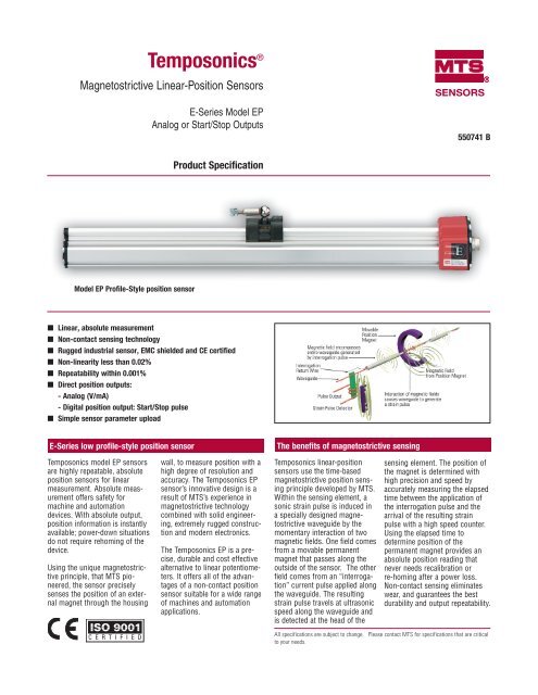
Temposonics ®Magnetostrictive Linear-Position SensorsE-Series Model EPAnalog or Start/Stop OutputsSENSORSR550741 BProduct SpecificationModel EP Profile-Style position sensor■ Linear, absolute measurement■ Non-contact sensing technology■ Rugged industrial sensor, EMC shielded and CE certified■ Non-linearity less than 0.02%■ Repeatability within 0.001%■ Direct position outputs:- Analog (V/mA)- Digital position output: Start/Stop pulse■ Simple sensor parameter uploadE-Series low profile-style position sensorThe benefits of magnetostrictive sensingTemposonics model EP sensorsare highly repeatable, absoluteposition sensors for linearmeasurement. Absolute measurementoffers safety formachine and automationdevices. With absolute output,position information is instantlyavailable; power-down situationsdo not require rehoming of thedevice.Using the unique magnetostrictiveprinciple, that MTS pioneered,the sensor preciselysenses the position of an externalmagnet through the housingwall, to measure position with ahigh degree of resolution andaccuracy. The Temposonics EPsensor’s innovative design is aresult of MTS’s experience inmagnetostrictive technologycombined with solid engineering,extremely rugged constructionand modern electronics.The Temposonics EP is a precise,durable and cost effectivealternative to linear potentiometers.It offers all of the advantagesof a non-contact positionsensor suitable for a wide rangeof machines and automationapplications.Temposonics linear-positionsensors use the time-basedmagnetostrictive position sensingprinciple developed by MTS.Within the sensing element, asonic strain pulse is induced ina specially designed magnetostrictivewaveguide by themomentary interaction of twomagnetic fields. One field comesfrom a movable permanentmagnet that passes along theoutside of the sensor. The otherfield comes from an “interrogation”current pulse applied alongthe waveguide. The resultingstrain pulse travels at ultrasonicspeed along the waveguide andis detected at the head of thesensing element. The position ofthe magnet is determined withhigh precision and speed byaccurately measuring the elapsedtime between the application ofthe interrogation pulse and thearrival of the resulting strainpulse with a high speed counter.Using the elapsed time todetermine position of thepermanent magnet provides anabsolute position reading thatnever needs recalibration orre-homing after a power loss.Non-contact sensing eliminateswear, and guarantees the bestdurability and output repeatability.All specifications are subject to change. Please contact MTS for specifications that are criticalto your needs.
- Page 2 and 3: Temposonics low profile-style EP li
- Page 4 and 5: Temposonics low profile-style EP li
- Page 6: How to order (continued)Optional ex
Temposonics ®Magnetostrictive Linear-Position <strong>Sensors</strong>E-Series Model EPAnalog or Start/Stop OutputsSENSORSR550741 BProduct SpecificationModel EP Profile-Style position sensor■ Linear, absolute measurement■ Non-contact sensing technology■ Rugged industrial sensor, EMC shielded and CE certified■ Non-linearity less than 0.02%■ Repeatability within 0.001%■ Direct position outputs:- Analog (V/mA)- Digital position output: Start/Stop pulse■ Simple sensor parameter uploadE-Series low profile-style position sensorThe benefits of magnetostrictive sensingTemposonics model EP sensorsare highly repeatable, absoluteposition sensors for linearmeasurement. Absolute measurementoffers safety formachine and automationdevices. With absolute output,position information is instantlyavailable; power-down situationsdo not require rehoming of thedevice.Using the unique magnetostrictiveprinciple, that <strong>MTS</strong> pioneered,the sensor preciselysenses the position of an externalmagnet through the housingwall, to measure position with ahigh degree of resolution andaccuracy. The Temposonics EPsensor’s innovative design is aresult of <strong>MTS</strong>’s experience inmagnetostrictive technologycombined with solid engineering,extremely rugged constructionand modern electronics.The Temposonics EP is a precise,durable and cost effectivealternative to linear potentiometers.It offers all of the advantagesof a non-contact positionsensor suitable for a wide rangeof machines and automationapplications.Temposonics linear-positionsensors use the time-basedmagnetostrictive position sensingprinciple developed by <strong>MTS</strong>.Within the sensing element, asonic strain pulse is induced ina specially designed magnetostrictivewaveguide by themomentary interaction of twomagnetic fields. One field comesfrom a movable permanentmagnet that passes along theoutside of the sensor. The otherfield comes from an “interrogation”current pulse applied alongthe waveguide. The resultingstrain pulse travels at ultrasonicspeed along the waveguide andis detected at the head of thesensing element. The position ofthe magnet is determined withhigh precision and speed byaccurately measuring the elapsedtime between the application ofthe interrogation pulse and thearrival of the resulting strainpulse with a high speed counter.Using the elapsed time todetermine position of thepermanent magnet provides anabsolute position reading thatnever needs recalibration orre-homing after a power loss.Non-contact sensing eliminateswear, and guarantees the bestdurability and output repeatability.All specifications are subject to change. Please contact <strong>MTS</strong> for specifications that are criticalto your needs.
Temposonics low profile-style EP linear-position sensor parametersTemposonics E-Series model EP sensors are available with analogoutput or digital-pulse output. The analog outputs include voltage,(0 to 10 Vdc, forward and reverse acting), and current, (4 to 20 mA,forward or reverse acting). Since the outputs are direct, no signalconditioning electronics are needed when interfacing with controllersor meters.Active sensor strokeMeasuring rangeforward actingPosition magnetreserve actingThe available digital-pulse output is Start/Stop. Here the sensorrequires a start signal from a controller or interface card toinitiate the measurement cycle. The sensor generates a stopsignal at the end of the measurement cycle that is used to stopthe controller’s counter clock. The elapsed time between theStart and Stop signals is directly proportional to the magnet’sposition along the active stroke length. The controller can calculatethe absolute position of the magnet from the time value andthe sensor’s unique gradient value, (inverse of the speed for theultrasonic pulse traveling in the sensor’s waveguide).START/STOPStart PulseStart Pulse“reflection”Time between Start and Stoppulses is proportionalto magnet positionFor applications using smart sensor interfaces the Start/Stop output,(option R3), can provide a sensor parameter upload ability. The followingsensor parameters are available for upload:- Measuring range- Offset- Gradient (Inverse speed of sensing pulse)- Status- Manufacturer number+ Start Input signals- Start to sensorStopPulse+ Stop- StopOutput signalsfrom sensorParameters SpecificationMeasured Variable: DisplacementResolution:Analog: InfiniteDigital: 1 ÷ [gradient x crystal freq. (MHz) xcirculations]; controller dependent.Non-Linearity: 1.5 kHzStart/Stop: Controller dependentMeasuring Range: 50 to 1525 mm (2 to 60 in.)Operating Conditions: Temperature: - 40 to 75 °C (- 40 to 167 °F)Relative humidity: 90% no condensation.Ingress protection: IP65 if mating cableconnector is correctly fitted.Shock test: 100 g (single hit) IEC-Standard68-2-27Vibration rating: 10 g/10 - 2000 HzIEC-Standard 68-2-6EMC Test: Electromagnetic emission EN 50081-1Electromagnetic immunity EN 50082-2EN 61000-4-2/3/4/6, Level 3/4, Criteria A,CE qualifiedOperating Voltage: +24 Vdc nominal (-15 or +20%)Polarity protection: up to -30 VdcOvervoltage protection: up to 36 VdcCurrent drain: Analog: 50 - 140 mAStart/Stop: 50 - 100 mA(stroke length dependent)Dielectric withstand voltage: 500 V,(DC ground to machine ground)Connection type: 6-pin male D60 connectorElectronic head: Aluminum housingSensor extrusion: Aluminum (Temposonics profile style)Mounting:Adjustable mounting feet or T-slot nut(M5 threads) in base channel.Magnet type: Captive-sliding magnets or floating magnets,(open ring or block).The sensor also features over-voltage protection to 36 Vdc andreverse polarity protection to 30 Vdc on input voltage connections.All outputs are absolute rather than incremental so that power-downsituations do not require re-homing.2 <strong>MTS</strong> <strong>Sensors</strong> Product Specification 550741 B
Temposonics low profile-style EP linear-position sensorThe Temposonics model EP sensor offers modular construction, flexible mounting configurations and easy installation. Position measurementsare non-contact via a permanent magnet that is moved along the profile extrusion housing.EP sensor with style “S” captive-sliding magnet54 mm(2.1 in.)39 mm(1.5 in.)19 mm(0.75 in.)Sensorhead8 mm(0.3 in.)46 mm(1.8 in.)Null35 mm(1.4 in.)Beginning of stroke - Null positionBall-jointed arm (M5 thread, vertical 18˚ / horizontal 360˚)Mounting foot57 mm (2.2 in.)Stroke length14.5 mm(0.57 in.)Dead zone68 mm(2.7 in.)40 mm(1.6 in.)57 mm (2.2 in.)2 mm (0.08 in.)35.5 mm(1.4 in.)50 mm(1.97 in.)68 mm (2.7 in.)63.5 mm(2.5 in.)EP sensor with style “V” captive-sliding magnet19 mm(0.75 in.)Beginning of stroke -Null positionBall jointed arm (M5 thread, 18˚ Rotation)50 mm(1.97 in.)58 mm (2.3 in.)48.5 mm (1.91 in.)9.5 mm (.37 in.)48.5 mm(1.91 in.)54.5 mm(2.1 in.)EP sensor with floating style “M” (open ring) magnet35 mm(1.4 in.)Beginning of stroke - Null positionMounting support , screw(non-ferrous material)20.7 mm(0.81 in.)Maximum gap3 mm(± 1 mm)(0.12 in. ± .04 in.)Ø 5.5 mm (0.21 in.)for M5 or #10 screw41 mm(1.6 in.)EP sensor with block style “L” magnetBeginning of stroke - Null position32.5 mm(1.28 in.) Mounting supportMagnetØ 4.3 mm(0.17 in.)31 mm(1.22 in.)19.5 mm(0.77 in.)6 mm(0.24 in.)20 mm(0.79 in.)Maximum gap3 mm (± 2 mm)(0.12 in. ± .08 in.)3 <strong>MTS</strong> <strong>Sensors</strong> Product Specification 550741 B
Temposonics low profile-style EP linear-position sensorSelection of position magnets (included with sensor)A choice of two magnet mounting configurations are available with the EP model sensor; the captive-sliding magnet or the “floating” typemagnet. Captive-sliding magnets utilize slide bearings of special material that reduce friction, and if required, help mitigate dirt build up. Theslide bearings are designed to operate dry, requiring no external lubrication or maintenance.The floating magnets (open ring or block style)mount on the moving machine part and travel justabove the sensor’s profile extrusion. The openring magnet (style M) requires a minimum distanceaway from ferrous metals to allow propersensor output. It must be mounted using non-ferrousscrews and a non-ferrous support bracket,or utilize a non-ferrous spacer of at least 5 mm(0.2 in.) thickness.The block magnet (style L) can be mounted usingferrous metal screws and support bracket.However, the support bracket can not extendbeyond 11 mm (0.43 in.) from the top of themagnet, unless it is made of non-ferrous material.The magnet should be installed with a perpendicularorientation relative to the top surface of thesensor extrusion as shown on page 3. Optimalperformance is achieved when this orientationremains consistent throughout the full measurementstroke range.Wiring and connectorsSensor integral connector (D60 Male)Pinout/wire color code (extension cable)Pin no. Wire color Function FunctionDigital-pulse outputsAnalog outputs1 Gray (-) Stop for Start/Stop 0 to10 Vdcor 4 to 20 mA2 Pink (+) Stop for Start/Stop Return for pin 13 Yellow (+) Start for Start/Stop 10 to 0 Vdcor 20 to 4 mA4 Green (-) Start for Start/Stop Return for pin 35 Red or Brown +24 Vdc (+20%, -15%) +24 Vdc (+20%, -15%)6 White DC Ground (for supply) DC Ground (for supply)Integral D6 connector (male) as viewed from end of sensor4 3 265 114 mm(0.57 in.)Captive-sliding magnet, style Spart no. 25218243 mm(1.69 in.)14 mm(0.55 in.)Rotation:Vertical: 18°Horizontal: 360°Ball-jointed arm,M5 threadFloating (open ring) magnet, style Mpart no. 251416-260 °40 mm(1.58 in.)2 Holeseach 4.3 mm dia. (0.17 in.)on 23.9 mm dia. (0.94 in.)24.6 mm(0.97 in.)20.7 mm(0.81 in.)ID: 13.5 mm (0.53 in.)OD: 32.8 mm (1.29 in.)Thickness: 7.9 mm (0.312 in.)20 mm(0.79 in.)Cable connectors (field-installed D6 female)Mates with sensor’s integral connector18 mm(0.7 in.)24 mm(0.95 in.)14 mm(0.55 in.)18° rotationCaptive-sliding magnet, style Vpart no. 252184Ball-jointed arm,M5 thread9 mm(0.35 in.)19.5 mm(0.77 in.)11 mm (0.43 in.)O 4.3 mm(0.17 in.)D6 Straight-exit connectorpart no. 560700D6 90º connectorpart no. 560778Block magnet, style Lpart no. 25288731 mm(1.22 in.)54 mm (2.1 in.)37 mm (1.5 in)57 mm(2.24 in.)40 mm(1.58 in.)24 mm(0.95 in.)6 mm (0.24 in.)20 mm (0.79 in.)13.5 mm(0.53 in.)Note:Appropriate grounding of cable shield is required at the controller end.54 mm(2.1 in.)Attention:A grounding lug is provided near the connectorend of the sensor for a convenient connection toearth ground. Since the EP sensor’s aluminumhousing has an anodic coating the sensormounting feet, (part no. 400802), do not provideproper grounding. A ground wire connection tothe grounding lug is required.4 <strong>MTS</strong> <strong>Sensors</strong> Product Specification 550741 B
How to orderPosition sensorWhen placing an order, buildthe model number using themodel number guide (to theright). A wide range ofE-Series position sensorconfigurations are available tomeet the demands of yourparticular application.If you have any questionsabout how to apply E-Seriesposition sensors, contact<strong>MTS</strong> Applications Engineeringor your local <strong>MTS</strong> distributor.Both of these resources areavailable to assist you indesigning an effectiveposition sensing system to fityour application.Note:Temposonics EP sensorsinclude two mounting feet(part number 400802). Oneadditional mounting foot isincluded for every additional500 mm (20 in.).EP =SENSOR MODELProfile styleHOUSING STYLEMagnets included with all EP sensors:S = Captive-sliding magnet with joint at top (Part no. 252182)V = Captive-sliding magnet with joint at front (Part no. 252184)M = Floating Magnet, (open ring) (part no. 251416-2)L = Floating Magnet, (block style) (part no. 252887)STROKE LENGTH____M = Millimeters (Encode in 5 mm increments)___. _ U = Inches and tenths (Encode in 0.1 in. incrementsCONNECTION TYPEConnectorD60 = 6-pin DIN connector, integral, standardINPUT VOLTAGE1 = +24 Vdc (+20%, -15%)OUTPUTAnalog - voltageVO = 0 to +10 Vdc and +10 to 0 VdcAnalog - currentAO = 4 to 20 mAA1 = 20 to 4 mAE PD 6 01 2 3 4 5 6 7 8 9 10 11 12 13 141Stroke length notes:Profile (EP) stroke range = 2 - 60 in. (50 - 1525 mm.)AccessoriesDigital - pulseR0 = Start/StopR3 = Start/Stop with sensor parameters upload functionDescription Function/Notes Part no.Mounting feet, standard (spares) Model EP sensors come with mounting feet 400802Joint-rod Sleeve (1 in.) For use with model EP sensors with “S” or “V” style magnets 401603Ball-jointed arm, straight For use with model EP sensors with “S” or “V” style magnets 401913Magnets and float optionsDescription Function/Notes Part no.Small open ring magnet (spare) Style M, “floating” magnet (included with EP sensors) 251416-2Block style magnet (spare) Style L “floating” magnet (included with EP sensors) 252887Captive-sliding magnet (spare) Style S captive-sliding magnet with joint at top (included with EP sensors) 252182Captive-sliding magnet (spare) Style V captive-sliding magnet with joint at front (included with EP sensors) 252184Field-installed connectorsDescription Function/Notes Part no.6-Pin DIN connector, straight Female, straight exit, mates to D60 connection type (see page 4). 5607006-Pin DIN connector, 90° Female, 90° exit, mates to D60 connection type (see page 4). 560778Joint rodused with captive-sliding magnets(1) Sleeve, part no. 401603(2) Ball-jointed arm, part no. 40191314 mm(0.55 in.)M5 threadsRotation: 18˚allowable22 mm(0.87 in.)9 mm(0.35 in.)(2) (1)27 mm(1.06 in.)M5 insidethread0.213 in. dia.through 4 holes1.9 mm(0.075 in.)Width = 14.5 mm (0.57 in.)Mounting footStandard mounting footpart no. 40080227.9 mm(1.1 in.)50 mm (1.97 in.)68 mm(2.68 in)9.1 mm(0.36 in.)9.1 mm(0.36 in.)304 SST5<strong>MTS</strong> <strong>Sensors</strong> Product Specification 550741 B
How to order (continued)Optional extension rods (for use with captive-sliding magnets)Extension rod lengths Part no.60.3 mm (2.375 in.) 401768-285.7 mm (3.375 in.) 401768-3111.1 mm (4.375 in.) 401768-4161.9 mm (6.375 in.) 401768-6187.3 mm (7.375 in.) 401768-7212.7 mm (8.375 in.) 401768-8238.1 mm (9.375 in.) 401768-9263.5 mm (10.375 in.) 401768-10314.3 mm (12.375 in.) 401768-12365.1 mm (14.375 in.) 401768-14Extension rod lengths Part no.390.5 mm (15.375 in.) 401768-15466.7 mm (18.375 in.) 401768-18517.5 mm (20.375 in.) 401768-20542.9 mm (21.375 in.) 401768-21619.1 mm (24.375 in.) 401768-24771.5 mm (30.375 in.) 401768-30923.9 mm (36.375 in.) 401768-361076.3 mm (42.375 in.) 401768-421228.7 mm (48.375 in.) 401768-481533.5 mm (60.375 in.) 401768-6015.2 mm(0.60 in.)(both ends)Extension rodpart no. 401768-XX9.5 mm(0.375 in.)M5-0.8 thread bore(both ends)Extension cable with connectors for the D6, (D60), connection typeDD6 =DA =DJ =DK =SENSOR CONNECTION TYPEFemale connector, (straight exit), and standard (part no. 530026) cable (PVC jacket) forsensors with D6 or D60 connectorFemale connector, (90° exit), and standard (part no. 530026) cable (PVC jacket) forsensors with D6 or D60 connectorFemale connector, (straight exit), and (part no. 530045) cable, (black polyurethane jacketfor higher resistance to moisture and oil), for sensors with D6 or D60 connectorFemale connector, (90° exit), and (part no. 530045) cable, (black polyurethane jacketfor higher resistance to moisture and oil), for sensors with D6 or D60 connectorCABLE LENGTHSFor standard length cables up to 100 ft005 = 5 ft. 050 = 50 ft.015 = 15 ft. 100 = 100 ft.025 = 25 ft.For custom length cables over 100 ft_ _ _ = Cable length (maximum cable length is dependent on the outputselected; consult <strong>MTS</strong> Applications Engineering.)CABLE TERMINATION (2 or 3 characters depending on option selected)P0 = Pigtail connection, (no connector).D6M = D6 male connector, (straight exit). Only available with the D6 option above.D6F = D6 Female connector, (straight exit). Only available with the D6 option above.DAF = D6 Female connector, (90 degrees exit). Only available with the DA option above.Part Number: 05-06 550741 Revision B<strong>MTS</strong> and Temposonics are registered trademarks of <strong>MTS</strong> Systems Corporation.All other trademarks are the property of their respective owners.All Temposonics sensors are covered by US patent number 5,545,984. Additional patents are pending.Printed in USA. Copyright © 2006 <strong>MTS</strong> Systems Corporation. All Rights Reserved.SENSORSRUNITED STATES<strong>MTS</strong> Systems Corporation<strong>Sensors</strong> Division3001 Sheldon DriveCary, NC 27513Tel: (800) 633-7609Fax: (919) 677-0200(800) 498-4442www.mtssensors.comsensorsinfo@mts.comGERMANY<strong>MTS</strong> Sensor TechnologieGmbH & Co. KGAuf dem Schüffel 9D - 58513 LüdenscheidTel: +49 / 23 51 / 95 87-0Fax: +49 / 23 51 / 56 491www.mtssensor.deinfo@mtssensor.deJAPAN<strong>MTS</strong> <strong>Sensors</strong> TechnologyCorporationUshikubo Bldg.737 Aihara-cho, Machida-shiTokyo 194-0211, JapanTel: + 81 (42) 775 / 3838Fax:+ 81 (42) 775 / 5516www.mtssensor.co.jpinfo@mtssensor.co.jp


