Axial Piston Variable Displacement Motor A6VM - Group VH A/S
Axial Piston Variable Displacement Motor A6VM - Group VH A/S
Axial Piston Variable Displacement Motor A6VM - Group VH A/S

You also want an ePaper? Increase the reach of your titles
YUMPU automatically turns print PDFs into web optimized ePapers that Google loves.
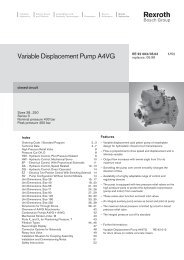
IndustrialHydraulicsElectric Drivesand ControlsLinear Motion andAssembly TechnologiesPneumaticsServiceAutomationMobileHydraulics<strong>Axial</strong> <strong>Piston</strong><strong>Variable</strong> <strong>Displacement</strong> <strong>Motor</strong> <strong>A6VM</strong>RE 91 604/06.03Replaces: 05.99Open and closed circuitsSizes 28 to 1000Series 6Sizes 28 to 200 Nominal pressure 400 barMaximum pressure 450 barSizes 250 to 1000 Nominal pressure 350 barMaximum pressure 400 barContentsOrdering Code / Standard Program 2...3Technical Data 4...7HD - Hydraulic Control, Pilot Pressure Dependent 8...10HZ - Hydraulic Two-Point Control 11EP - Electrical Control With Proportional Solenoid 12...14EZ - Electrical Two-Point Control, With Solenoid 15HA - Automatic Control, High-Pressure Dependent 16...19HD - Hydraulic Control, Speed Dependent 20...21Unit Dimensions, Size 28 22...24Unit Dimensions, Size 55 25...27Unit Dimensions, Size 80 28...30Unit Dimensions, Size 107 31...33Unit Dimensions, Size 140 34...36Unit Dimensions, Size 160 37...39Unit Dimensions, Size 200 40...42Unit Dimensions, Size 250 43...45Unit Dimensions, Size 355 46...48Unit Dimensions, Size 500 49...51Unit Dimensions, Size 1000 52...54Flushing and Boost Pressure Valve 55Counterbalance Valve BVD 56...57Speed Measurement 58Swivel Angle Indicator 59Connectors for Solenoids (for EP, EZ, HA.U, HA.R, DA only) 60Installation and Startup Instructions 61Safety Instructions 62Features– <strong>Variable</strong> displacement axial piston motor of bent axis designfor hydrostatic transmissions in open and closed circuits– For use in mobile and stationary applications– The wide control range enables the variable displacementmotor to satisfy the requirement for high rotational speedand high torque.– The displacement is continuously variable from V g max toV g min = 0.– The output speed depends on the flow capacity of thepumps and the displacement of the motor.– The torque increases with the pressure differential betweenthe high and low pressure side and with increasing displacement.– Wide control range with hydrostatic transmissions– Wide selection of regulating and control devices– Cost savings as no need for shiftable gearboxes and possibilityto use smaller pumps– Rugged, compact bearing system with long service life– High power density– Favorable start-up efficiency– Low moment of inertia– Large swivel range
2/64 Bosch Rexroth AG | Mobile Hydraulics <strong>A6VM</strong> | RE 91 604/06.03Ordering Code / Standard ProgramPressure fluidMineral oil (no character), HFD for sizes 250-1000 only in combination with long-life bearing “L”HFB, HFC pressure fluid Sizes 28 to 200 (no character)Sizes 250 to 1000 (only in combination with long-life bearing “L”)<strong>Axial</strong> piston unitbent-axis type, variableDrive shaft bearing 28...200 250 355 500 1000Standard bearing (no character) ● ● ● ● –Long-life bearing – ● ● ● ● LOperation mode<strong>Motor</strong> (A6VE plug-in motor, see RE 91606)Size<strong>Displacement</strong> Vg max (cm 3 ) 28 55 80 107 140 160 200 250 355 5001000Control device 28 55 80 107 140 160 200 250 355 500 1000Hydraulic control,∆p = 10 bar HD1 ● ● ● ● ● ● ● ● ● ● ● HD1Pilot pressure dependent∆p = 25 bar HD2 ● ● ● ● ● ● ● ● ● ● ● HD2∆p = 35 bar HD3 – – – – – – – ● ● ● ● HD3Hydraulic two-point controlHZ – – – – – – – ● ● ● ● HZHZ1 ● – – – ● ● ● – – – – HZ1HZ3 – ● ● ● – – – – – – – HZ3Electrical control, with12 V EP1 ● ● ● ● ● ● ● ● ● ● ● EP1proportional solenoid (sizes 28 to 200) 1 ) 24 V EP2 ● ● ● ● ● ● ● ● ● ● ● EP2Electrical two-point control,12 V EZ1 ● – – – ● ● ● ● ● ● ● EZ1with solenoid24 V EZ2 ● – – – ● ● ● ● ● ● ● EZ212 V EZ3 – ● ● ● – – – – – – – EZ324 V EZ4 – ● ● ● – – – – – – – EZ4Automatic control, without pressure rise HA1 ● ● ● ● ● ● ● ● ● ● ● HA1High-pressure dependent with pressure rise ∆p = 100 bar HA2 ● ● ● ● ● ● ● ● ● ● ● HA2Hydraulic control, speed dependentpSt/pHD = 3/100, hydraulic travel direction valveDA – – – – – – – ● ● ● ❍ DApSt/pHD = 5/100, hydraulic travel direction valveDA1 ● ● ● ● ● ● ● – – – – DA1electrical travel direction valve 12 V DA2 ● ● ● ● ● ● ● – – – – DA2+ electrical Vg max switch 24 V DA3 ● ● ● ● ● ● ● – – – – DA3pSt/pHD = 8/100, hydraulic travel direction valveDA4 ● ● ● ● ● ● ● – – – – DA4electrical travel direction valve 12 V DA5 ● ● ● ● ● ● ● – – – – DA5+ electrical Vg max switch 24 V DA6 ● ● ● ● ● ● ● – – – – DA6Pressure control (for HD, EP only) 28 55 80 107 140 160 200 250 355 500 1000without pressure control (no character) ● ● ● ● ● ● ● ● ● ● ●Pressure control direct ● ● ● ● ● ● ● ● ● ● ● Ddirect, with 2nd pressure setting ● ● ● ● ● ● ● 2 ) 2 ) 2 ) 2 ) Eremotely controlled – – – – – – – ● ● ● ● GOverriding HA control (for HA1, HA2 only)without override (no character) ● ● ● ● ● ● ● ● ● ● ●Hydraulic override ● ● ● ● ● ● ● ● ● ● ● TElectrical override 12 V ● ● ● ● ● ● ● – – – – U124 V ● ● ● ● ● ● ● – – – – U2Electrical override 12 V ● ● ● ● ● ● ● – – – – R1+ electrical travel direction valve 24 V ● ● ● ● ● ● ● – – – – R2SeriesSeries 6, index 3 63Direction of rotationwhen viewing shaft end, alternatingSetting range for displacement 3 ) 28 55 80 107 140 160 200 250 355 500 1000Vg min = 0 to 0.8 Vg max (no character) ● ● ● ● ● ● ● – – – –Vg min = 0 to 0.4 Vg max Vg max = Vg max to 0.8 Vg max – – – – – – – ● ● ● ● 1Vg min > 0.4 Vg max to 0.8 Vg max Vg max = Vg max to 0.8 Vg max – – – – – – – ● ● ● ● 21) with proportioning valve (sizes 250 to 1000) 2) supplied as standard with D version (sizes 250 to 1000)3) please specify precise values for V g min and V g max in plain text when placing your order: V g min = ... cm 3 , V g max = ... cm 3E<strong>A6VM</strong>W
RE 91 604/06.03 | <strong>A6VM</strong> Mobile Hydraulics | Bosch Rexroth AG 3/64A6V M / 6 3 W - VPressure fluid<strong>Axial</strong> piston unitTransmission shaft bearingOperation modeSizeControl deviceSeries/IndexDirection of rotationSetting range for displacementSealsFKM (fluor-caoutchouc)VShaft end 28 55 80 107 140 160 200 250 355 500 1000Splined shaft DIN 5480 ● ● ● ● – ● ● – – – – A● ● ● ● ● ● – ● ● ● ● ZCylindrical shaft with key DIN 6885 – – – – – – – ● ● ● ● PMounting flange toISO 3019-2 – 4-hole ● ● ● ● ● ● ● ● – – – BISO 3019-2 – 8-hole – – – – – – – – ● ● ● HService line connections 28 55 80 107 140 160 200 250 355 500 1000Ports A, B: SAE rear 01 0 ● ● ● ● ● ● ● ● ● ● ● 0107 ● ● ● ● ● ● ● ● ● ● ● 017Ports A, B: SAE side, opposite 02 0 ● ● ● ● ● ● ● ● ● ● ● 0207 ● ● ● ● ● ● ● ● ● ● ● 027Port plate for fitting 08 0 – – – – – – – ❍ – – – 080a counterbalance valvePorts A, B: SAE side, opposite + rear 15 0 – – – – – – – ● ● ● ● 150Port plate with pressure limiter, 37 0 – – – ● – – – – – – – 370for fitting a counterbalance valve 1 ) 2 ) 38 0 – ● ● ● ● ● – – – – – 380Valvesno valves 0with flushing and boost pressure valve 7Speed measurement 28 55 80 107 140 160 200 250 355 500 1000no speed measurement (no character) ● ● ● ● ● ● ● ● ● ● ●prepared for speed measurement (ID) 3 ) ● ● ● ● ● ● ● – – – – Dprepared for speed measurement (HDD) 3 ) – ● ● ● ❍ ● ● ❍ ❍ ❍ ❍ FSwivel angle indicatorno swivel angle indicator (no character) ● ● ● ● ● ● ● ● ● ● –with optical swivel angle indicator – – – – – – – ● ● ● ● Vwith electrical swivel angle indicator – – – – – – – ● ● ● ● EConnectors for solenoids (sizes 28 to 200 only) 4 ) EP1/2 EZ1/2 EZ3/4 HA.U. HA.R. DA.DEUTSCH DT04-2P-EP04 injection molded, without bidirectional quenching diode ● ● – – – ● P2-pin injection molded, with bidirectional quenching diode – ❍ – – – ❍ Qwith lead, without bidirectional quenching diode 5 ) 6 ) ● ● ● ● ● ● THirschmann according to DIN EN 175 301-803-A, without bidirectional quenching diode 6 ) ● ● ● ● ● ● HStart of controlat Vg min (standard for HA) ● ● ● ● ● ● ● ● ● ● ● Aat Vg max (standard for HD, HZ, EP, EZ, DA) ● ● ● ● ● ● ● ● ● ● ● B1) only possible in combination with HD, EP, HA control2) complete order recommended, counterbalance valve, page 56 to 573) complete order recommended, speed sensor, page 584) for sizes 250 to 1000, the DIN connector is a Hirschmann one as standard (no character)5) under development for size 286) not for new projects (sizes 28 to 200)● = available ❍ = under development – = not available = preferred program
4/64 Bosch Rexroth AG | Mobile Hydraulics <strong>A6VM</strong> | RE 91 604/06.03Technical DataPressure fluidBefore starting project planning, please refer to our datasheets RE 90220 (mineral oil), RE 90221 (environmentallyfriendlypressure fluids) and RE 90223 (HF pressure fluids) fordetailed information regarding the choice of pressure fluids andconditions of use.The <strong>A6VM</strong> variable displacement motor is not suitable for usewith HFA. If HFB, HFC and HFD or environmentally-friendlypressure fluids are being used, the constraints regarding technicaldata and seals mentioned in RE 90221 and RE 90223must be observed.If necessary, please contact us to discuss the type ofpressure fluid you intend to use.Selection chartViscosity n in mm 2 /s2500-40 -201600100060040020010060402010VG 220 20 40 60 80 100VG 32VG 46VG 68VG 10016003616n opt.Viscosity rangeWe recommend that a viscosity (at operating temperature) foroptimum efficiency and service life purposes ofν opt = optimum viscosity 16 to 36 mm 2 /sbe chosen, taken the circulation temperature (closed circuit)and reservoir temperature (open circuit) into account.Limits of viscosity rangeThe following values apply in extreme cases:Sizes 28 to 200:ν min = 5 mm 2 /sshort-term (t < 3 min) at max. permitted temperatureof t max = +115°C.ν max = 1600mm 2 /s,short-term (t < 3 min) with cold start (p < 30 bar,n ≤ 1000 rpm, t min = -40°C).Sizes 250 to 1000:ν min = 10 mm 2 /sshort-term (t < 3 min) at max. permitted leakage-fueltemperature of t max = +90°C.ν max = 1600 mm 2 /s,short-term (t < 3 min) with cold start (p < 30 bar,n ≤ 1000 rpm, t min = -25°C).Note that the maximum pressure fluid temperature must not beexceeded locally either (e.g. during storage).Special measures are necessary at temperatures between-25°C and -40°C. Please contact us.See RE 90300-03-B for detailed information about use at lowtemperatures.5-40t min = -40 C5-25 -10 0° 10 30 50 70 90 115Temperature t in °CPressure fluid temperature ranget max = +115 CDetails regarding the choice of pressure fluidThe correct choice of pressure fluid requires knowledge of theoperating temperature in relation to the ambient temperature: ina closed circuit the circulation temperature, in an open circuitthe reservoir temperature.The pressure fluid should be chosen so that the viscosity in theoperating temperature range is within the optimum area (V opt) -the shaded area of the selection chart. We recommend that thehigher viscosity class be selected in each case.Example: At an operating temperature of 60°C, the viscosityclasses VG 46 and VG 68 are within the optimum viscosityarea (ν opt., shaded field). In this case we would recommendVG 68.Please note: The leakage-fuel temperature, which is affected bypressure and rotational speed, is always higher than the circulationtemperature or reservoir temperature. At no pointin the system must the temperature be higher than 115°C(sizes 28 to 200) or 90°C (sizes 250 to 1000).If this cannot be achieved due to unusual operating parametersor high ambient temperatures, we recommend flushing of thecase via port U or the use of a flushing and boost pressurevalve (see page 55).
RE 91 604/06.03 | <strong>A6VM</strong> Mobile Hydraulics | Bosch Rexroth AG 5/64Technical DataFilteringThe finer the filtering, the cleaner the fluid and the greater theservice life of the axial piston unit.To ensure proper function of the axial piston unit, the pressurefluid must have a purity class of at least20/18/15 according to ISO 4406.At very high pressure fluid temperatures (90°C to max. 115°C,not permitted for sizes 250 to 1000), a purity class of at least19/17/14 according to ISO 4406 is required.Long-Life bearing (sizes 250 to 1000)For long service life and use with HF pressure fluids.Same external dimensions as motor with standardbearing. A long-life bearing can be retrofitted.Flushing of bearing and case via port U recommended.Flow (recommended)Size 250 355 500 1000q v flow (L/min) 10 16 16 16Please contact us if these purity classes cannot be achieved.Temperature range of shaft sealThe FKM shaft seal is suitable for case temperatures of-25°C to +115°C for sizes 28 to 200 and-25°C to +90°C for sizes 250 to 1000Note:A NBR shaft seal is necessary at temperatures below -25°C(permitted temperature range: -40°C to +90°C).Please contact us.Operational pressure rangeMaximum pressure on port A or B(pressure data according to DIN 24312)for sizes 28 to 200Nominal pressure p N __________________________________________ 400 barMaximum pressure p max ______________________________________ 450 barTotal pressure (pressure A + pressure B) p max __________ 700 barfor sizes 250 to 1000Nominal pressure p N __________________________________________ 350 barMaximum pressure p max ______________________________________ 400 barTotal pressure (pressure A + pressure B) p max __________ 700 barPlease note:Sizes 28 to 200: At the shaft end Z, a nominal pressure of p N =315 bar is permitted for the driven shaft end that is subjected totransverse bending (pinions, V-belts)!Sizes 250 to 1000: Please contact us.In cases of pulsating loading above 315 bar, we recommendthe version with splined shaft A (sizes 28 to 200) or splinedshaft Z (sizes 250 to 1000).Direction of flowCase drain pressureThe service life of the sealing ring is affected by the speed ofthe motor and the case drain pressure. The permitted loadingwith intermittent case drain pressure depends on the rotationalspeed (see chart). Short-term (t < 5 s) pressure spikes of upto 6 bar absolute are permitted.The average permanent case drain pressure must not exceed3 bar absolute.The pressure in the case must be equal to or greater than theexternal pressure on the shaft seal.The pure mechanical resistance to case pressure isapproximately 20 bar.Sizes 28 to 2006Perm. pressure pabs. max. in barPerm. pressure pabs. max. in bar5432sizes107, 140sizes 160, 200size 28size 55size 8012000 4000 6000 8000 10000Rotational speed n in rpmSizes 250 to 10006size 2505size 5004size 3553size 1000210 500 1000 1500 2000 2500 3000Rotational speed n in rpm3500Clockwise direction of rotation Counterclockwise direction of rotationA to BSpeed rangeB to ANo limit to minimum speed n min . If uniform motion is required,n min must not be less than 50 rpm. See table on page 6 formaximum speed.Effect of case pressure on start of controlAn increase in the case pressure has an effect on the followingsettings when control of the variable displacement motor begins:HA1T (sizes 28 to 200) ______________________ increaseHD, EP, HA, HA.T (sizes 250 to 1000): _________ increaseDA : _______________________________________ reductionThe start of control is set in the factory at a case pressure ofp abs = 2 bar (sizes 28 to 200) and p abs = 1 bar (sizes 250 to 1000).
8/64 Bosch Rexroth AG | Mobile Hydraulics <strong>A6VM</strong> | RE 91 604/06.03HD - Hydraulic Control, Pilot Pressure DependentThe pilot pressure dependent hydraulic system permitscontinuous control of the displacement according to thepilot pressure signal. The control is proportional to thepilot pressure present on port X.Normal version:- start of control at V g max (max. torque, min. speed)- end of control at V g min (min. torque, max. permitted speed)Please note:- Maximum permitted pilot pressure: 100 bar- The required charge oil is taken from the high pressure.Therefore, a ∆p of at least 15 bar on the supply pressure isneeded. If the ∆p on the supply pressure is < 15 bar (e.g.when idle), an auxiliary pressure of at least 15 bar above thesupply pressure must be applied on port G via an externalnon-return valve.- Please state the required start of control in plain text whenplacing your order, e.g.: start of control at 10 barThe following only applies to sizes 250 to 1000:- The start of control and the HD characteristic are influencedby the pressure in the case. A rise in pressure in the casecauses an increase in the start of control and a correspondingparallel movement of the performance curve(see page 5).- Fluid will escape from port X at the rate of 0.3 l/min due tointernal leakage (operating pressure > pilot pressure). Theactuation must be designed appropriately to ensure correctcontrol pressure.HD1: pilot pressure rise ∆p S = 10 barA rise in pilot pressure of 10 bar on port X causes a reduction inthe displacement from V g max to 0 cm 3 (sizes 28 to 200) or from V gmax to 0.2 V g max (sizes 250 to 1000).Start of control (setting range) _________________ 2 – 20 barDefault setting: Start of control at 3 bar (end at 13 bar)Pilot pressureriseStart of controlSetting range32,530284sizes 28...2002sizes 250...1000HD1(Dps = 10 bar)0 0,2 0,4 0,6 0,8 1,0V g 0 Vg / Vg max V g max242016128Pilot pressure ∆pS in bar<strong>Displacement</strong>HD2: pilot pressure rise ∆p S = 25 barA rise in pilot pressure of 25 bar on port X causes a reduction inthe displacement from V g max to 0 cm 3 (sizes 28 to 200) or fromVg max to 0.2 V g max (sizes 250 to 1000).Start of control, setting range _________________Default setting: Start of control at 10 bar (end at 35 bar)Pilot pressure8070605040302010sizes 28...200sizes 250...10005 HD2(Dps = 25 bar)0 0,2 0,4 0,6 0,8 1,0V g 0 Vg / Vg max V g maxriseStart of controlSetting range<strong>Displacement</strong>HD3: pilot pressure rise ∆p S = 35 bar908070605040302010sizes7250...1000HD3(Dps = 35 bar)0 0,2 0,4 0,6 0,8 1,0V g 0 Vg / Vg max V g maxPilot pressureriseStart of controlSetting rangePilot pressure ∆pS in barA rise in pilot pressure of 35 bar on port X causes a reduction inthe displacement from V g max auf 0.2 V g max (sizes 250 to 1000).Start of control, setting range ___________________ 7 – 50 barDefault setting: Start of control at 10 bar (end at 45 bar)<strong>Displacement</strong>5 – 50 barPilot pressure ∆pS in bar
RE 91 604/06.03 | <strong>A6VM</strong> Mobile Hydraulics | Bosch Rexroth AG 9/64HD - Hydraulic Control, Pilot Pressure DependentHD1, HD2, HD3:Hydraulic control, pilot pressure dependentSizes 28 to 200HD.D: pressure control, directThe pressure control overlays the HD function. If the loadmoment or a reduction in the swivel angle of the motor causesthe system pressure to rise, the motor will start to swivel to agreater angle when the pressure reaches the value set on thepressure control.The increase in the displacement and the resulting reductionin pressure cause the controller deviation to decrease. Withthe increase in displacement the motor develops more torque,while the pressure remains constant.Setting range on pressure control valve:Sizes 28 to 200 ___________________________ 80 – 400 barSizes 250 to 1000 ________________________ 80 – 350 barSizes 28 to 200Sizes 250 to 1000Sizes 250 to 1000
10/64 Bosch Rexroth AG | Mobile Hydraulics <strong>A6VM</strong> | RE 91 604/06.03HD - Hydraulic Control, Pilot Pressure DependentHD.E: pressure control, directwith 2nd pressure settingSizes 28 to 200Connecting an external pilot pressure to port G2 allows thepressure regulator setting to be overridden and a secondpressure setting to be used.Required pilot pressure on port G2:Sizes 28 to 200 ________________________ p St = 20 - 50 barPlease specify the 2nd pressure setting in plain text whenplacing your order.Sizes 28 to 200HD.G: pressure control, remoteSizes 250 to 1000When the specified pressure is reached, the remote pressurecontrol regulates the motor continuously up to the maximumdisplacement V g max. A pressure limiter (not in the scope ofsupply) controls the internal discharge stop valve. The pressurelimiter is separate from the motor and is connected to X3. If thepressure setpoint value is not reached, the valve is subjectedto even pressure from both sides, in addition to the springforce, and remains closed. The pressure setpoint lies between80 bar and 350 bar. When this pressure is obtained on theseparate pressure limiter, the pressure limiter opens and thepressure on the reservoir side of the spring reduces. Theinternal control valve switches and the motor swivels to maximumdisplacement V g max.The default value for the differential pressure on the controlvalve is 25 bar. We recommend the following external pressurelimiter:DBD 6 (hydraulic) to RE 25402The max. line length must not exceed 2 m.Sizes 250 to 1000Sizes 250 to 1000 (HD.D)Pressure control with 2nd pressure setting provided asstandard with HD.D (see page 9).Connecting an external pilot pressure to port G2 allowsthe pressure regulator setting to be overridden and a secondpressure setting to be used.Required pilot pressure on port G2:Sizes 250 to 1000 ________________________ p St ≥ 100 barPlease specify the 2nd pressure setting in plain text whenplacing your order.
RE 91 604/06.03 | <strong>A6VM</strong> Mobile Hydraulics | Bosch Rexroth AG 11/64HZ - Hydraulic Two-Point ControlHydraulic two-point control allows the displacement to be setto V g min or V g max by switching the pilot pressure on port X onor off.HZ: Hydraulic two-point controlSizes 250 to 1000no pilot pressurepilot pressure switched on (> 10 bar)position at V g maxposition at V g maxNormal version:- start of control at V g max (max. torque, min. speed)- end of control at V g min (min. torque, max. permitted speed)V g 0<strong>Displacement</strong>100V g maxPilot pressure ∆pS in barPlease note:- Maximum permitted pilot pressure: 100 bar- The required charge oil is taken from the high pressure.Therefore, a ∆p of at least 15 bar on the supply pressure isneeded. If the ∆p on the supply pressure is < 15 bar (whenidle), an auxiliary pressure of at least 15 bar above the supplypressure must be applied on port G via an external nonreturnvalve.The following only applies to sizes 250 to 1000:- Fluid will escape from port X at the rate of 0.3 l/min due tointernal leakage (operating pressure > pilot pressure).The actuation must be designed appropriately to ensurecorrect control pressure.HZ1: Hydraulic two-point controlSizes 28, 140, 160, 200HZ3: Hydraulic two-point controlSizes 55, 80, 107
12/64 Bosch Rexroth AG | Mobile Hydraulics <strong>A6VM</strong> | RE 91 604/06.03EP - Electrical Control With Proportional SolenoidElectrical control using a proportional solenoid (sizes 28 to200) or proportioning valve (sizes 250 to 1000) permits continuouscontrol of the displacement according to an electricalsignal. The control is proportional to the applied electrical controlcurrent.In the case of sizes 250 to 1000, an external pressure of p min =30 bar is necessary for the charge oil supply to port P (p max =100 bar).Normal version:— start of control at V g max (max. torque, min. speed)— end of control at V g min (min. torque, max. permitted speed)(12 V) (24 V)V g max1600<strong>Displacement</strong>V g 0V gV g max(12 V) (24 V)max140012001000800600400200800max700600500400300200100sizes 28 to 200sizes 250 to 10000 0,2 0,4 0,6 0,8 1,0 EP1 EP2Please note:- The required charge oil is taken from the high pressure, soa ∆p of at least 15 bar on the supply pressure is needed. Ifthe ∆p on the supply pressure is < 15 bar (when idle), anauxiliary pressure of at least 15 bar above the supplypressure must be applied on port G via an external nonreturnvalve.- The start of control and the EP characteristic are influencedby the pressure in the case. A rise in pressure in the casecauses an increase in the start of control and a correspondingparallel movement of the performance curve (sizes 250to 1000, see page 5).Control current I in mATechnical data, EP1 EP2solenoid in EP1, EP2Voltage 12 V (±20 %) 24 V (±20 %)Control current sizes 28 to 200Control starts at V g max 400 mA 200 mAControl ends at V g min 1200 mA 600 mAControl current sizes 250 to 1000Control starts at V g max 900 mA 450 mAControl ends at V g min 1400 mA 700 mAMaximum current 1,54 A 0,77 ANominal resistance (at 20°C) 5,5 Ω 22,7 ΩDither frequency 100 Hz 100 HzOperating time 100 % 100 %Degree of protection see connector design, page 60The rate of control or limiting of the displacement (limiting theswiveling range) can be achieved electrically using the followingcontrol units:– MC control unit (see RE 95050)– RC control unit (see RE 95200)– PV proportional amplifier (see RE 95023)– VT 2000 electrical amplifier, series 5X (see RE 29904)(for stationary application)EP1, EP2:Sizes 28 to 200EP1, EP2:Sizes 250 to 1000Electrical control with proportionalsolenoidElectrical control withproportioning valveProportional pressurereduction valve DRE 4K(see RE 29 181)
RE 91 604/06.03 | <strong>A6VM</strong> Mobile Hydraulics | Bosch Rexroth AG 13/64EP - Electrical Control With Proportional SolenoidEP.D: Electrical control with pressure control,directThe pressure control overlays the EP function. If the loadmoment or a reduction in the swivel angle of the motor causesthe system pressure to rise, the motor will start to swivel to agreater angle when the pressure reaches the value set on thepressure control.The increase in the displacement and the resulting reductionin pressure cause the controller deviation to decrease. Withthe increase in displacement the motor develops more torque,while the pressure remains constant.Setting range on pressure-control valve:Sizes 28 to 200 ___________________________ 80 – 400 barSizes 250 to 1000 ________________________ 80 – 350 barSizes 28 to 200EP.E: pressure control, direct with 2nd pressuresettingSizes 28 to 200Connecting an external pilot pressure to port G2 allows thepressure regulator setting to be overridden and a secondpressure setting to be used.Required pilot pressure on port G2:Sizes 28 to 200 ________________________ p St = 20 - 50 barPlease specify the 2nd pressure setting in plain text whenplacing your order.Sizes 28 to 200Sizes 250 to 1000 (EP.D)Sizes 250 to 1000Pressure control with 2nd pressure setting provided asstandard with EP.D (see circuit diagram).Connecting an external pilot pressure to port G2 allows thepressure regulator setting to be overridden and a secondpressure setting to be used.Required pilot pressure on port G2:Sizes 250 to 1000 ________________________p St ≥ 100 barPlease specify the 2nd pressure setting in plain text whenplacing your order.
14/64 Bosch Rexroth AG | Mobile Hydraulics <strong>A6VM</strong> | RE 91 604/06.03EP - Electrical Control With Proportional SolenoidEP.G: Electrical control with pressure control,remoteSizes 250 to 1000When the specified pressure is reached, the remote pressurecontrol regulates the motor continuously up to the maximumdisplacement V g max. A pressure limiter (not in the scope ofsupply) controls the internal discharge stop valve. The pressurelimiter is separate from the motor and is connected to X3.If the specified pressure value is not reached, the valve issubjected to even pressure from both sides, in addition to thespring force, and remains closed. The pressure setpoint liesbetween 80 bar and 350 bar. When this pressure is reachedon the separate pressure limiter, the limiter opens and thepressure on the reservoir side of the spring reduces. Theinternal control valve switches and the motor swivels to maximumdisplacement V g max. The default value for the differentialpressure on the control valve is 25 bar. We recommend thefollowing external pressure limiter:DBD 6 (hydraulic) to RE 25402The max. line length must not exceed 2 m.Sizes 250 to 1000
RE 91 604/06.03 | <strong>A6VM</strong> Mobile Hydraulics | Bosch Rexroth AG 15/64EZ - Electrical Two-Point Control, With SolenoidElectrical two-point control with a solenoid allows thedisplacement to be set to V g min or V g max by switching theelectrical current to the solenoids on or off.EZ1, EZ2: Electrical two-point controlSizes 28, 140, 160, 200Please note:- The required charge oil is taken from the high pressure, soa ∆p of at least 15 bar on the supply pressure is needed.If the ∆p on the supply pressure is < 15 bar (when idle),an auxiliary pressure of at least 15 bar above the supplypressure must be applied on port G via an external nonreturnvalve.Technical data, EZ1 EZ2solenoid in EZ1, EZ2Voltage 12 V (±20 %) 24 V (±20 %)Neutral position V g max de-energized de-energizedV g min position Current on Current onNominal resistance (at 20°C) 5.5 Ω 21.7 ΩNominal output 26.2 W 26.5 WActive current, minimum required 1.32 A 0.67 AOperating time 100 % 100 %Degree of protection see connector design, page 60EZ3, EZ4: Electrical two-point controlSizes 55, 80, 107Technical data, EZ3 EZ4solenoid in EZ3, EZ4Voltage 12 V (±20 %) 24 V (±20 %)Neutral position V g max de-energized de-energizedV g min position Current on Current onNominal resistance (at 20°C) 4.8 Ω 19.2 ΩNominal output 30 W 30 WActive current, minimum required 1.5 A 0.75 AOperating time 100 % 100 %Degree of protection see connector design, page 60EZ1, EZ2: Electrical two-point controlSizes 250 to 1000
16/64 Bosch Rexroth AG | Mobile Hydraulics <strong>A6VM</strong> | RE 91 604/06.03HA - Automatic Control, High-Pressure DependentIn the case of automatic high-pressure dependent control, thedisplacement is set automatically according to the operatingpressure.The control unit measures the internal operating pressure atA or B (no control line required) and, when the pressurereaches the setpoint value of V g min set on the controller, swivelswith increasing operating pressure to V g max .Normal version HA1, HA2:Start of control at V g min (min. torque, max. speed)End of control at V g max (max. torque, min. speed)Please note:- For safety reasons, winch drives are not permitted with startof control at V g min (default with HA).HA1:approximate with no pressure riseA rise in operating pressure of ∆p ≤10 bar causes an increasein the displacement from 0 cm 3 to Vg max (sizes 28 to 200) orfrom 0,2 V g max to V g max (sizes 250 to 1000).- The required charge oil is taken from the high pressure, so a∆p of at least 15 bar on the supply pressure is needed. If the∆p on the supply pressure is < 15 bar (when idle), an auxiliarypressure of at least 15 bar above the supply pressuremust be applied on port G via an external non-return valve.- The start of control and the HA characteristic are influencedby the pressure in the case. A rise in pressure in the casecauses an increase in the start of control and a correspondingparallel movement of the performance curve. Onlywith HA1, HA2, HA.T (sizes 250 to 1000) and HA1T (sizes28 to 200), see page 5.- Fluid will escape from port X at the rate of 0.3 l/min due tointernal leakage (operating pressure > pilot pressure).The actuation must be designed appropriately to ensurecorrect control pressure.Only with HA.T control.Sizes 28 to 200Start of control, setting rangeSizes 28 to 200 ___________________________ 80 – 350 barSizes 250 to 1000 ________________________ 80 – 340 barPlease state the required start of control in plain text whenplacing your order, e.g.: start of control at 300 bar350Operating pressure ∆p in bar30025020015010080Start of control, setting rangePressure rise≤ ∆p 10 barSizes 250 to 1000500sizes 28 to 200sizes 250 to 10000 0,2 0,4 0,6 0,8 1,0V g 0V gV g maxV g max<strong>Displacement</strong>
RE 91 604/06.03 | <strong>A6VM</strong> Mobile Hydraulics | Bosch Rexroth AG 17/64HA - Automatic Control, High-Pressure DependentHA2: pressure rise ∆p = 100 barSizes 28 to 200A rise in operating pressure of ∆p = 100 bar causes anincrease in the displacement from 0 cm 3 to Vg max (sizes 28 to200) or from 0.2 V g max to V g max (sizes 250 to 1000).Start of control, setting rangeSizes 28 to 200 ___________________________ 80 – 350 barSizes 250 to 1000 ________________________ 80 – 250 barPlease state the required start of control in plain text whenplacing your order, e.g.: start of control at 200 barOperating pressure ∆p in bar35030025020015010080Start of control, setting rangePressure rise∆p 100 barSizes 250 to 1000500sizes 28 to 200sizes 250 to 10000 0,2 0,4 0,6 0,8 1,0V g 0V gV g maxV g max<strong>Displacement</strong>
18/64 Bosch Rexroth AG | Mobile Hydraulics <strong>A6VM</strong> | RE 91 604/06.03HA - Automatic Control, High-Pressure Dependent (override)HA.T: Hydraulic override of pressuresetpointIn the case of HA control, the start of control can be influencedby applying a pilot pressure to port X.For each 1 bar of pilot pressure, the start of control is reducedby 17 bar (sizes 28 to 200) or 8 bar (sizes 250 to 1000).Examples (sizes 28 to 200):Start of control setting 300 bar 300 barPilot pressure on port X 0 bar 10 bargives start of control at 300 bar 130 barIf the override is only intended to set the max. displacement(motor swivels to V g max ), a maximum pilot pressure of 100 baris permitted.Sizes 28 to 200HA.U1, U2: Electrical override of pressuresetpointWith the HA control, high-pressure dependent control can beoverridden by an electrical signal on a solenoid. In the caseof an override, the variable displacement motor swivels to themaximum swivel angle.The start of control can be set to between 80 and 300 bar(specify value in plain text when placing your order).Technical data solenoid b U1 U2(electrical override)Voltage 12 V (±20 %) 24 V (±20 %)No override de-energized de-energizedPosition at V g max Current on Current onNominal resistance (at 20°C) 4.8 Ω 19.2 ΩNominal output 30 W 30 WActive current, minimum required 1.5 A 0.75 AOperating time 100 % 100 %Degree of protection see connector design, page 60HA1U1, HA1U2: Sizes 28 to 200Sizes 250 to 1000HA2U1, HA2U2: Sizes 28 to 200
RE 91 604/06.03 | <strong>A6VM</strong> Mobile Hydraulics | Bosch Rexroth AG 19/64HA - Automatic Control, High-Pressure Dependent (override)HA.R1, R2: Electrical override of pressuresetpoint using electrical traveldirection valveHA1R1, HA1R2: Sizes 28 to 200With the HA control, high-pressure dependent control can beoverridden by an electrical signal on solenoid b. In the case ofan override, the variable displacement motor swivels to themaximum swivel angle.The travel direction valve ensures that the preselected pressureoutlet of the hydraulic motor always controls the swivel angle,even if the high pressure side changes (e.g. during a descent).This therefore prevents an undesirable swiveling of the variabledisplacement motor to a greater displacement.Depending on the direction of rotation (direction of travel), thetravel direction valve (see page 21) can be actuated throughthe compression spring or solenoid a.Technical data, solenoid a R1 R2(travel direction valve)Voltage 12 V (±20 %) 24 V (±20 %)Direction Operating Solenoid aof rotation pressure incounter-clockwise B actuated actuatedclockwise A de-energized de-energizedHA2R1, HA2R2: Sizes 28 to 200Nominal resistance (at 20°C) 5.5 Ω 21.7 ΩNominal output 26.2 W 26.5 WActive current, minimum required 1.32 A 0.67 AOperating time 100 % 100 %Degree of protection see connector design, page 60Technical data, solenoid b R1 R2(electrical override)Voltage 12 V (±20 %) 24 V (±20 %)No override de-energized de-energizedPosition at V g max Current on Current onNominal resistance (at 20°C) 4.8 Ω 19.2 ΩNominal output 30 W 30 WActive current, minimum required 1.5 A 0.75 AOperating time 100 % 100 %Degree of protection see connector design, page 60
20/64 Bosch Rexroth AG | Mobile Hydraulics <strong>A6VM</strong> | RE 91 604/06.03DA - Hydraulic Control, Speed DependentThe <strong>A6VM</strong> variable displacement motor with speed-dependenthydraulic control is best used for hydrostatic transmissions incombination with the A4VG variable displacement pump withDA control.The pilot pressure derived from the driving speed of the A4VGvariable displacement pump, together with the operating pressure,regulate the swivel angle of the hydraulic motor.Increasing driving speed, i.e. rising pilot pressure, causes themotor to swivel to a lower displacement (lower torque, higherspeed), depending on the operating pressure.If the operating pressure rises above the value set on thecontroller, the motor swivels to a higher displacement (highertorque, lower speed).The design of a drive with DA control must be carried out usingthe technical data relating to the A4VG variable displacementpump with DA control.Detailed Information can be obtained from our sales departmentsand on the Internet at www.boschrexroth.com/da-control.DA, DA1, DA4:Hydraulic control, speed dependent withhydraulic travel direction valveThe travel direction valve is operated according to thedirection of rotation (direction of travel) using the controlpressures X 1 or X 2 ).Direction of rotation Operating pressure in Pilot pressure inclockwise A X 1counter-clockwise B X 2Sizes 28 to 200Please note:- The start of control and the DA characteristic are influencedby the pressure in the case. A rise in pressure in the casecauses a drop in the start of control and a correspondingparallel movement of the performance curve (see page 5).Sizes 250 to 1000
RE 91 604/06.03 | <strong>A6VM</strong> Mobile Hydraulics | Bosch Rexroth AG 21/64DA - Hydraulic Control, Speed DependentDA2, DA3, DA5, DA6:Hydraulic control, speed dependent withelectrical travel direction valve + electricalV g max switchDepending on the direction of rotation (direction of travel), thetravel direction valve can be actuated through the compressionspring or solenoid a.By connecting an electrical current to solenoid b, the controllercan be overridden and the motor adjusted to max. displacement(high torque, low speed) (so called “electrical V g maxswitch”).Technical data, DA2, DA5 DA3, DA6solenoids a and bVoltage 12 V (±20 %) 24 V (±20 %)Direction Operating Solenoid aof rotation pressure incounter-clockwise B de-energized de-energizedclockwise A actuated actuatedNominal resistance (at 20°C) 5.5 Ω 21.7 ΩNominal output 26.2 W 26.5 WActive current, minimum required 1.32 A 0.67 AOperating time 100 % 100 %Degree of protection see connector design, page 60Sizes 28 to 200Electrical travel direction valve (for DA, HA.R)The travel direction valve of the motor is switched using the4/3 directional-control valve on the control unit of the drivingpump. Usually, this provides trouble-free drivability of the drivenmachine.However, with unfavorable operating parameters this can leadto undesired conditions (jerky, uncontrolled braking whenswitching the drive lever into neutral). The reason is that thetravel direction valve of the motor operates as soon as thepump is in theneutral position, causing the motor controller to detect a brakingpressure, which is then used to control the swivel angle.To prevent this, the existing switching position on the traveldirection valve must be retained while the pump is being putinto the neutral position, i.e. an energized valve must remainenergized. This can be done using the circuit shown below.24 V DCK1.1K2.1VNRV1Drive switchreverseK1.2forwardsSolenoidPumpA3 B3TravelK1directionA2valveThe motor should swivel more slowly than the pump.We therefore recommend that actuation be delayed byapproximately 0.8s. This prevents too long a delay whenreversing lightweight units.K224 V DCDA2, DA3, DA5, DA6 controlHA1R.,HA2R. control (see page 19)Solenoid a on travel direction valve
22/64 Bosch Rexroth AG | Mobile Hydraulics <strong>A6VM</strong> | RE 91 604/06.03Unit Dimensions, Size 28Hydraulic control, pilot pressure dependent HD1, HD2Hydraulic two-point control HZ1Service line ports A/B lateral, opposite (02)Before finalizing your design, pleaserequest approved installation drawing.Shaft endsA Splined shaftDIN 5480W30x2x30x14x9gZSplined shaftDIN 5480W25x1.25x30x18x9gView ZService line ports A/B lateral,opposite (02)Service line ports A/Bat rear (01)1 )1 )1) DIN 332 center holePortsTightening torque, maxA, B Service line ports (high pressure series) SAE J518, 3/4 inThreaded fitting A/B DIN 13 M10x1.5; 17 deep see safety instructionsT 1 Leakage-fuel port DIN 3852 M18x1.5; 12 deep 140 NmT 2 Leakage fluid/oil drain 2 ) DIN 3852 M18x1.5; 12 deep 140 NmX, X 1 , X 3 Pilot pressure port DIN 3852 M14x1.5; 12 deep 80 NmG Port for synchronous control of several DIN 3852 M14x1.5; 12 deep 80 Nmunits and for remote charge pressure 2 )G 2 Port for 2nd pressure setting 2 ) DIN 3852 M14x1.5; 12 deep 80 NmU Flow port 2 ) DIN 3852 M16x1.5; 12 deep 100 NmM 1 Measuring port for charge pressure 2 ) DIN 3852 M14x1.5; 12 deep 80 Nm2 ) closed
RE 91 604/06.03 | <strong>A6VM</strong> Mobile Hydraulics | Bosch Rexroth AG 23/64Unit Dimensions, Size 28Hydraulic control, pilot pressure dependent,with pressure control, direct HD.DBefore finalizing your design, pleaserequest approved installation drawing.Hydraulic control, pilot pressure dependent, withpressure control, direct and 2nd pressure setting HD.EElectrical control with proportional solenoidEP1, EP2Electrical control (proportional solenoid)with pressure control, direct EP.DElectrical control (proportional solenoid) withpressure control, direct and 2nd pressure setting EP.E
24/64 Bosch Rexroth AG | Mobile Hydraulics <strong>A6VM</strong> | RE 91 604/06.03Unit Dimensions, Size 28Electrical two-point control with solenoidEZ1, EZ2Before finalizing your design, pleaserequest approved installation drawing.Automatic control, high-pressure dependent HA1, HA2,and hydraulic override HA1T, HA2THA1 and HA2, X closedHA1T and HA2T, X openAutomatic control, high-pressure dependent andelectric override HA1U1, HA2U2Automatic control, high-pressure dependent, electricoverride and elec. travel direction valve HA1R1, HA2R2Hydraulic control, speed dependent andhydraulic travel direction valve DA1, DA4Hydraulic control, speed dependent, elec. travel directionvalve and elec. V g max switch DA2, DA3, DA5, DA6X 1 , X 2 with 8B-ST threaded connection to DIN 2353-CL
RE 91 604/06.03 | <strong>A6VM</strong> Mobile Hydraulics | Bosch Rexroth AG 25/64Unit Dimensions, Size 55Hydraulic control, pilot pressure dependent HD1, HD2Hydraulic two-point control HZ3Service line ports A/B lateral, opposite (02)Before finalizing your design, pleaserequest approved installation drawing.Shaft endsASplined shaftDIN 5480W35x2x30x16x9gZSplined shaftDIN 5480W30x2x30x14x9gService line ports A/Blateral, opposite (02)View ZService line ports A/Bat rear (01)1 )1 )1) DIN 332 center holePortsTightening torque, maxA, B Service line port (high pressure series) SAE J518, 3/4 inThreaded fitting A/B DIN 13 M10x1.5; 17 deep see safety instructionsT 1 Leakage-fuel port DIN 3852 M18x1.5; 12 deep 140 NmT 2 Leakage fluid/oil drain 2 ) DIN 3852 M18x1.5; 12 deep 140 NmX, X 1 , X 3 Pilot pressure port DIN 3852 M14x1.5; 12 deep 80 NmG Port for synchronous control of several DIN 3852 M14x1.5; 12 deep 80 Nmunits and for remote charge pressure 2 )G 2 Port for 2nd pressure setting 2 ) DIN 3852 M14x1.5; 12 deep 80 NmU Flow port 2 ) DIN 3852 M18x1.5; 12 deep 140 NmM 1 Measuring port for charge pressure 2 ) DIN 3852 M14x1.5; 12 deep 80 Nm2 ) closed
26/64 Bosch Rexroth AG | Mobile Hydraulics <strong>A6VM</strong> | RE 91 604/06.03Unit Dimensions, Size 55Hydraulic control, pilot pressure dependent,with pressure control, direct HD.DBefore finalizing your design, pleaserequest approved installation drawing.Hydraulic control, pilot pressure dependent, withpressure control, direct and 2nd pressure setting HD.EHydraulic controlHZ3Electrical control with proportional solenoidEP1, EP2Electrical control (proportional solenoid)with pressure control, direct EP.DElectrical control (proportional solenoid) withpressure control, direct and 2nd pressure setting EP.E
RE 91 604/06.03 | <strong>A6VM</strong> Mobile Hydraulics | Bosch Rexroth AG 27/64Unit Dimensions, Size 55Electrical two-point control with solenoidEZ3, EZ4Before finalizing your design, pleaserequest approved installation drawing.Automatic control, high-pressure dependent HA1, HA2,and hydraulic override HA1T, HA2THA1 and HA2, X closedHA1T and HA2T, X openAutomatic control, high-pressure dependent andelectric override HA1U1, HA2U2Automatic control, high-pressure dependent, electricoverride and elec. travel direction valve HA1R1, HA2R2Hydraulic control, speed dependent andhydraulic travel direction valve DA1, DA4Hydraulic control, speed dependent, elec. travel directionvalve and elec. V g max switch DA2, DA3, DA5, DA6X 1 , X 2 with 8B-ST threaded connection to DIN 2353-CL
28/64 Bosch Rexroth AG | Mobile Hydraulics <strong>A6VM</strong> | RE 91 604/06.03Unit Dimensions, Size 80Hydraulic control, pilot pressure dependent HD1, HD2Hydraulic two-point control HZ3Service line ports A/B lateral, opposite (02)Before finalizing your design, pleaserequest approved installation drawing.Shaft endsASplined shaftDIN 5480W40x2x30x18x9gZSplined shaftDIN 5480W35x2x30x16x9gService line ports A/Blateral, opposite (02)View ZService line ports A/Bat rear (01)1 )1 )1) DIN 332 center holePortsTightening torque, maxA, B Service line port (high pressure series) SAE J518, 1 inThreaded fitting A/B DIN 13 M12x1.75; 17 deep see safety instructionsT 1 Leakage-fuel port DIN 3852 M18x1.5; 12 deep 140 NmT 2 Leakage fluid/oil drain 2 ) DIN 3852 M18x1.5; 12 deep 140 NmX, X 1 , X 3 Pilot pressure port DIN 3852 M14x1.5; 12 deep 80 NmG Port for synchronous control of several DIN 3852 M14x1.5; 12 deep 80 Nmunits and for remote charge pressure 2 )G 2 Port for 2nd pressure setting 2 ) DIN 3852 M14x1.5; 12 deep 80 NmU Flow port 2 ) DIN 3852 M18x1.5; 12 deep 140 NmM 1 Measuring port for charge pressure 2 ) DIN 3852 M14x1.5; 12 deep 80 Nm2 ) closed
RE 91 604/06.03 | <strong>A6VM</strong> Mobile Hydraulics | Bosch Rexroth AG 29/64Unit Dimensions, Size 80Hydraulic control, pilot pressure dependent,with pressure control, direct HD.DBefore finalizing your design, pleaserequest approved installation drawing.Hydraulic control, pilot pressure dependent, withpressure control, direct and 2nd pressure setting HD.EHydraulic controlHZ3Electrical control with proportional solenoidEP1, EP2Electrical control (proportional solenoid)with pressure control, direct EP.DElectrical control (proportional solenoid) withpressure control, direct and 2nd pressure setting EP.E
30/64 Bosch Rexroth AG | Mobile Hydraulics <strong>A6VM</strong> | RE 91 604/06.03Unit Dimensions, Size 80Electrical two-point control with solenoidEZ3, EZ4Before finalizing your design, pleaserequest approved installation drawing.Automatic control, high-pressure dependent HA1, HA2,and hydraulic override HA1T, HA2THA1 and HA2, X closedHA1T and HA2T, X openAutomatic control, high-pressure dependent andelectric override HA1U1, HA2U2Automatic control, high-pressure dependent, electricoverride and elec. travel direction valve HA1R1, HA2R2Hydraulic control, speed dependent andhydraulic travel direction valve DA1, DA4Hydraulic control, speed dependent, elec. travel directionvalve and elec. V g max switch DA2, DA3, DA5, DA6X 1 , X 2 with 8B-ST threaded connection to DIN 2353-CL
RE 91 604/06.03 | <strong>A6VM</strong> Mobile Hydraulics | Bosch Rexroth AG 31/64Unit Dimensions, Size 107Hydraulic control, pilot pressure dependent HD1, HD2Hydraulic two-point control HZ3Service line ports A/B lateral, opposite (02)Before finalizing your design, pleaserequest approved installation drawing.Shaft endsA Splined shaftDIN 5480W45x2x30x21x9gZSplined shaftDIN 5480W40x2x30x18x9gService line ports A/Blateral, opposite (02)View ZService line ports A/Bat rear (01)1 )1 )1) DIN 332 center holePortsTightening torque, maxA, B Service line port (high pressure series) SAE J518, 1 inThreaded fitting A/B DIN 13 M12x1.75; 17 deep see safety instructionsT 1 Leakage-fuel port DIN 3852 M18x1.5; 12 deep 140 NmT 2 Leakage fluid/oil drain 2 ) DIN 3852 M18x1.5; 12 deep 140 NmX, X 1 , X 3 Pilot pressure port DIN 3852 M14x1.5; 12 deep 80 NmG Port for synchronous control of several DIN 3852 M14x1.5; 12 deep 80 Nmunits and for remote charge pressure 2 )G 2 Port for 2nd pressure setting 2 ) DIN 3852 M14x1.5; 12 deep 80 NmU Flow port 2 ) DIN 3852 M18x1.5; 12 deep 140 NmM 1 Measuring port for charge pressure 2 ) DIN 3852 M14x1.5; 12 deep 80 Nm2) closed
32/64 Bosch Rexroth AG | Mobile Hydraulics <strong>A6VM</strong> | RE 91 604/06.03Unit Dimensions, Size 107Hydraulic control, pilot pressure dependent,with pressure control, direct HD.DBefore finalizing your design, pleaserequest approved installation drawing.Hydraulic control, pilot pressure dependent, withpressure control, direct and 2nd pressure setting HD.EHydraulic controlHZ3Electrical control with proportional solenoidEP1, EP2Electrical control (proportional solenoid)with pressure control, direct EP.DElectrical control (proportional solenoid) withpressure control, direct and 2nd pressure setting EP.E
RE 91 604/06.03 | <strong>A6VM</strong> Mobile Hydraulics | Bosch Rexroth AG 33/64Unit Dimensions, Size 107Electrical two-point control with solenoidEZ3, EZ4Before finalizing your design, pleaserequest approved installation drawing.Automatic control, high-pressure dependent HA1, HA2,and hydraulic override HA1T, HA2THA1 and HA2, X closedHA1T and HA2T, X openAutomatic control, high-pressure dependent andelectric override HA1U1, HA2U2Automatic control, high-pressure dependent, electricoverride and elec. travel direction valve HA1R1, HA2R2Hydraulic control, speed dependent andhydraulic travel direction valve DA1, DA4Hydraulic control, speed dependent, elec. travel directionvalve and elec. V g max switch DA2, DA3, DA5, DA6X 1 , X 2 with 8B-ST threaded connection to DIN 2353-CL
34/64 Bosch Rexroth AG | Mobile Hydraulics <strong>A6VM</strong> | RE 91 604/06.03Unit Dimensions, Size 140Hydraulic control, pilot pressure dependent HD1, HD2Hydraulic two-point control HZ1Service line ports A/B lateral, opposite (02)Before finalizing your design, pleaserequest approved installation drawing.Shaft endsService line ports A/Blateral, opposite (02)View ZService line ports A/Bat rear (01)ASplined shaftDIN 5480W45x2x30x21x9gZSplined shaftDIN 5480W45x2x30x21x9g1 )1 )1) DIN 332 center holePortsTightening torque, maxA, B Service line port (high pressure series) SAE J518, 1 inThreaded fitting A/B DIN 13 M14x2; 19 deep see safety instructionsT 1 Leakage-fuel port DIN 3852 M26x1.5; 16 deep 230 NmT 2 Leakage fluid/oil drain 2 ) DIN 3852 M26x1.5; 16 deep 230 NmX, X 1 , X 3 Pilot pressure port DIN 3852 M14x1.5; 12 deep 80 NmG Port for synchronous control of several DIN 3852 M14x1.5; 12 deep 80 Nmunits and for remote charge pressure 2 )G 2 Port for 2nd pressure setting 2 ) DIN 3852 M14x1.5; 12 deep 80 NmU Flow port 2 ) DIN 3852 M22x1.5; 14 deep 210 NmM 1 Measuring port for charge pressure 2 ) DIN 3852 M14x1.5; 12 deep 80 Nm2) closed
RE 91 604/06.03 | <strong>A6VM</strong> Mobile Hydraulics | Bosch Rexroth AG 35/64Unit Dimensions, Size 140Hydraulic control, pilot pressure dependent,with pressure control HD.DBefore finalizing your design, pleaserequest approved installation drawing.Hydraulic control, pilot pressure dependent, with pressurecontrol, direct, with 2nd pressure setting HD.EElectrical control with proportional solenoidEP1, EP2Electrical control (proportional solenoid)with pressure control, direct EP.DElectrical control (proportional solenoid)with pressure control, remote EP.E
36/64 Bosch Rexroth AG | Mobile Hydraulics <strong>A6VM</strong> | RE 91 604/06.03Unit Dimensions, Size 140Electrical two-point control with solenoidEZ1, EZ2Before finalizing your design, pleaserequest approved installation drawing.Automatic control, high-pressure dependent HA1, HA2,and hydraulic override HA1T, HA2THA1 and HA2, X closedHA1T and HA2T, X openAutomatic control, high-pressure dependent andelectric override HA1U1, HA2U2Automatic control, high-pressure dependent, electricoverride and elec. travel direction valve HA1R1, HA2R2Hydraulic control, speed dependent andhydraulic travel direction valve DA1, DA4Hydraulic control, speed dependent, elec. travel directionvalve and elec. V g max switch DA2, DA3, DA5, DA6X 1 , X 2 with 8B-ST threaded connection to DIN 2353-CL
RE 91 604/06.03 | <strong>A6VM</strong> Mobile Hydraulics | Bosch Rexroth AG 37/64Unit Dimensions, Size 160Hydraulic control, pilot pressure dependent HD1, HD2Hydraulic two-point control HZ1Service line ports A/B lateral, opposite (02)Before finalizing your design, pleaserequest approved installation drawing.Shaft endsService line ports A/Blateral, opposite (02)View ZService line ports A/Bat rear (01)ASplined shaftDIN 5480W50x2x30x24x9gZSplined shaftDIN 5480W45x2x30x21x9g1 )1 )1) DIN 332 center holePortsTightening torque, maxA, B Service line port (high pressure series) SAE J518, 11/4 inThreaded fitting A/B DIN 13 M14x2; 19 deep see safety instructionsT 1 Leakage-fuel port DIN 3852 M26x1.5; 16 deep 230 NmT 2 Leakage fluid/oil drain 2 ) DIN 3852 M26x1.5; 16 deep 230 NmX, X 1 , X 3 Pilot pressure port DIN 3852 M14x1.5; 12 deep 80 NmG Port for synchronous control of several DIN 3852 M14x1.5; 12 deep 80 Nmunits and for remote charge pressure 2 )G 2 Port for 2nd pressure setting 2 ) DIN 3852 M14x1.5; 12 deep 80 NmU Flow port 2 ) DIN 3852 M22x1.5; 14 deep 230 NmM 1 Measuring port for charge pressure 2 ) DIN 3852 M14x1.5; 12 deep 80 Nm2) closed
38/64 Bosch Rexroth AG | Mobile Hydraulics <strong>A6VM</strong> | RE 91 604/06.03Unit Dimensions, Size 160Hydraulic control, pilot pressure dependent,with pressure control, direct HD.DBefore finalizing your design, pleaserequest approved installation drawing.Hydraulic control, pilot pressure dependent, withpressure control, direct and 2nd pressure setting HD.EElectrical control with proportional solenoidEP1, EP2Electrical control (proportional solenoid)with pressure control, direct EP.DElectrical control (proportional solenoid) withpressure control, direct and 2nd pressure setting EP.E
RE 91 604/06.03 | <strong>A6VM</strong> Mobile Hydraulics | Bosch Rexroth AG 39/64Unit Dimensions, Size 160Electrical two-point control with solenoidEZ1, EZ2Before finalizing your design, pleaserequest approved installation drawing.Automatic control, high-pressure dependent HA1, HA2,and hydraulic override HA1T, HA2THA1 and HA2, X closedHA1T and HA2T, X openAutomatic control, high-pressure dependent andelectric override HA1U1, HA2U2Automatic control, high-pressure dependent, electricoverride and elec. travel direction valve HA1R1, HA2R2Hydraulic control, speed dependent andhydraulic travel direction valve DA1, DA4Hydraulic control, speed dependent, elec. travel directionvalve and elec. V g max switch DA2, DA3, DA5, DA6X 1 , X 2 with 8B-ST threaded connection to DIN 2353-CL
40/64 Bosch Rexroth AG | Mobile Hydraulics <strong>A6VM</strong> | RE 91 604/06.03Unit Dimensions, Size 200Hydraulic control, pilot pressure dependent HD1, HD2Hydraulic two-point control HZ1Service line ports A/B lateral, opposite (02)Before finalizing your design, pleaserequest approved installation drawing.Shaft endsASplined shaftDIN 5480W50x2x30x24x9gView ZService line ports A/Blateral, opposite (02)Service line ports A/Bat rear (01)1 )1) DIN 332 center holePortsTightening torque, maxA, B Service line port (high pressure series) SAE J518, 11/4 inThreaded fitting A/B DIN 13 M14x2; 19 deep see safety instructionsT 1 Leakage-fuel port DIN 3852 M26x1.5; 16 deep 230 NmT 2 Leakage fluid/oil drain 2 ) DIN 3852 M26x1.5; 16 deep 230 NmX, X 1 , X3 Pilot pressure port DIN 3852 M14x1.5; 12 deep 80 NmG Port for synchronous control of several DIN 3852 M14x1.5; 12 deep 80 Nmunits and for remote charge pressure 2 )G 2 Port for 2nd pressure setting 2 ) DIN 3852 M14x1.5; 12 deep 80 NmU Flow port 2 ) DIN 3852 M22x1.5; 14 deep 210 NmM 1 Measuring port for charge pressure 2 ) DIN 3852 M14x1.5; 12 deep 80 Nm2) closed
RE 91 604/06.03 | <strong>A6VM</strong> Mobile Hydraulics | Bosch Rexroth AG 41/64Unit Dimensions, Size 200Hydraulic control, pilot pressure dependent,with pressure control, direct HD.DBefore finalizing your design, pleaserequest approved installation drawing.Hydraulic control, pilot pressure dependent, withpressure control, direct and 2nd pressure setting HD.EX 1 , X 2 with 8B-ST threaded connection to DIN 2353-CLElectrical control with proportional solenoidEP1, EP2Electrical control (proportional solenoid)with pressure control, direct EP.DElectrical control (proportional solenoid) withpressure control, direct and 2nd pressure setting EP.E
42/64 Bosch Rexroth AG | Mobile Hydraulics <strong>A6VM</strong> | RE 91 604/06.03Unit Dimensions, Size 200Electrical two-point control with solenoidEZ1, EZ2Before finalizing your design, pleaserequest approved installation drawing.Automatic control, high-pressure dependent HA1, HA2,and hydraulic override HA1T, HA2THA1 and HA2, X closedHA1T and HA2T, X openAutomatic control, high-pressure dependent andelectric override HA1U1, HA2U2Automatic control, high-pressure dependent, electricoverride and elec. travel direction valve HA1R1, HA2R2Hydraulic control, speed dependent andhydraulic travel direction valve DA1, DA4Hydraulic control, speed dependent, elec. travel directionvalve and elec. V g max switch DA2, DA3, DA5, DA6
RE 91 604/06.03 | <strong>A6VM</strong> Mobile Hydraulics | Bosch Rexroth AG 43/64Unit Dimensions, Size 250Hydraulic control, control-pressure dependent HD1, HD2, HD3Hydraulic two-point control HZService line ports A/B lateral, opposite (02)Before finalizing your design, pleaserequest approved installation drawing.1 )1)1) at rear for service line ports A/B (plate 01/15)View ZService line ports A/Blateral, opposite (02)Service line ports A/Bat rear (01)Service line ports A/B/A 1 /B 1lateral, opposite + at rear (15)
44/64 Bosch Rexroth AG | Mobile Hydraulics <strong>A6VM</strong> | RE 91 604/06.03Unit Dimensions, Size 250Before finalizing your design, pleaserequest approved installation drawing.Shaft endsZSplined shaftDIN 5480W50x2x30x24x9gPCyl. shaft,with adjusting springDIN 6885 AS14x9x801 )1 )1) DIN 332 center holePortsTightening torque, maxA, B Service line port (high pressure series) SAE J518, 11/4 inA 1, B 1 Additional service line ports for plate 15 SAE J518, 11/4 inThreaded fitting A/B DIN 13 M14x2; 19 deep see safety instructionsT 1 Leakage-fuel port DIN 3852 M22x1.5; 14 deep 210 NmT 2 Leakage fluid/oil drain 2 ) DIN 3852 M22x1.5; 14 deep 210 NmX Pilot pressure port DIN 3852 M14x1.5; 12 deep 80 NmX 3 Port for remote control valve DIN 3852 M14x1.5; 12 deep 80 NmP Connection for charge oil supply DIN 3852 M14x1.5; 12 deep 80 NmG Port for synchronous control of several DIN 3852 M14x1.5; 12 deep 80 Nmunits and for remote charge pressure 2 )G 2 Port for 2nd pressure setting 2 ) DIN 3852 M14x1.5; 12 deep 80 NmU Flow port 2 ) DIN 3852 M14x1.5; 12 deep 80 NmM Measuring port for charge pressure 2 ) DIN 3852 M14x1.5; 12 deep 80 NmM A , M B Measuring port for operating pressure 2 ) DIN 3852 M14x1.5; 12 deep 80 NmM St Measuring port for pilot pressure 2 ) DIN 3852 M14x1.5; 12 deep 80 Nm2) closed
RE 91 604/06.03 | <strong>A6VM</strong> Mobile Hydraulics | Bosch Rexroth AG 45/64Unit Dimensions, Size 250Hydraulic control, pilot pressure dependent,with pressure control, direct HD.D, remote control HD.GElectrical control with proportioning valveEP1, EP2Before finalizing your design, pleaserequest approved installation drawing.HD.D with G 2 , without X 3HD.G with X 3 , without G 2Electrical control (proportioning valve)with pressure control, direct EP.D. remote EP.GElectrical two-point control with solenoidEZ1, EZ2EP.D with G 2 , without X 3EP.G with X 3 , without G 2Automatic control, high-pressure dependent HA1, HA2,with hydraulic override HA1T, HA2THydraulic control, speed dependent DAHA1 and HA2, X closedHA1T and HA2T, X openX 1 , X 2 with B threaded connection B0-GEV 8L/M14x1.5-WD
46/64 Bosch Rexroth AG | Mobile Hydraulics <strong>A6VM</strong> | RE 91 604/06.03Unit Dimensions, Size 355Hydraulic control, pilot pressure dependent HD1, HD2, HD3Hydraulic two-point control HZService line ports A/B lateral, opposite (02)Before finalizing your design, pleaserequest approved installation drawing.1 )1)1 ) at rear for service line ports A/B (plate 01/15)View ZService line ports A/Blateral, opposite (02)Service line ports A/Bat rear (01)Service line ports A/B/A 1 /B 1lateral, opposite + at rear (15)
RE 91 604/06.03 | <strong>A6VM</strong> Mobile Hydraulics | Bosch Rexroth AG 47/64Unit Dimensions, Size 355Before finalizing your design, pleaserequest approved installation drawing.Shaft endsZSplined shaftDIN 5480W60x2x30x28x9gPCyl. shaft, withadjusting springDIN 6885 AS18x11x1001 )1 )1) DIN 332 center holePortsTightening torque, maxA, B Service line port (high pressure series) SAE J518, 11/2 inA 1, B 1 Additional service line ports for plate 15 SAE J518, 11/4 inThreaded fitting A/B DIN 13 M16x2; 24 deep see safety instructionsT 1 Leakage-fuel port DIN 3852 M33x2; 18 deep 540 NmT 2 Leakage fluid/oil drain 2 ) DIN 3852 M33x2; 18 deep 540 NmX, X 1 , X 2 Pilot pressure port DIN 3852 M14x1.5; 12 deep 80 NmX 3 Port for remote control valve DIN 3852 M14x1.5; 12 deep 80 NmP Connection for charge oil supply DIN 3852 M14x1.5; 12 deep 80 NmG Port for synchronous control of several DIN 3852 M14x1.5; 12 deep 80 Nmunits and for remote charge pressure 2 )G 2 Port for 2nd pressure setting 2 ) DIN 3852 M14x1.5; 12 deep 80 NmU Flow port 2 ) DIN 3852 M14x1.5; 12 deep 80 NmM Measuring port for charge pressure 2 ) DIN 3852 M14x1.5; 12 deep 80 NmM A , M B Measuring port for operating pressure 2 ) DIN 3852 M14x1.5; 12 deep 80 NmM St Measuring port for pilot pressure 2 ) DIN 3852 M14x1.5; 12 deep 80 Nm2) closed
48/64 Bosch Rexroth AG | Mobile Hydraulics <strong>A6VM</strong> | RE 91 604/06.03Unit Dimensions, Size 355Hydraulic control, pilot pressure dependent,with pressure control, direct HD.D, remote control HD.GElectrical control with proportioning valveEP1, EP2Before finalizing your design, pleaserequest approved installation drawing.HD.D with G 2 , without X 3HD.G with X 3 , without G 2Electrical control (proportioning valve)with pressure control, direct EP.D, remote EP.GElectrical two-point control with solenoidEZ1, EZ2EP.D with G 2 , without X 3EP.G with X 3 , without G 2Automatic control, high-pressure dependent HA1, HA2,with hydraulic override HA1T, HA2THydraulic control, speed dependent DAHA1 and HA2, X closedHA1T and HA2T, X open
RE 91 604/06.03 | <strong>A6VM</strong> Mobile Hydraulics | Bosch Rexroth AG 49/64Unit Dimensions, Size 500Hydraulic control, pilot pressure dependent HD1, HD2, HD3Hydraulic two-point control HZService line ports A/B lateral, opposite (02)Before finalizing your design, pleaserequest approved installation drawing.1 )1) 1) at rear for service line ports A/B (plate 01/15)View ZService line ports A/Blateral, opposite (02)Service line ports A/Bat rear (01)Service line ports A/B / A 1 / B 1lateral, opposite + at rear (15)
50/64 Bosch Rexroth AG | Mobile Hydraulics <strong>A6VM</strong> | RE 91 604/06.03Unit Dimensions, Size 500Before finalizing your design, pleaserequest approved installation drawing.Shaft endsZSplined shaftDIN 5480W70x3x30x22x9gPCyl. shaft,with adjusting springDIN 6885AS20x12x1001 )1 )1) DIN 332 center holePortsTightening torque, maxA, B Service line port (high pressure series) SAE J518, 11/2 inA 1, B 1 Additional service line ports for plate 15 SAE J518, 11/2 inThreaded fitting A/B DIN 13 M16x2; 24 deep see safety instructionsT 1 Leakage-fuel port DIN 3852 M33x2; 18 deep 540 NmT 2 Leakage fluid/oil drain 2 ) DIN 3852 M33x2; 18 deep 540 NmX, X 1 , X 2 Pilot pressure port DIN 3852 M14x1.5; 12 deep 80 NmX 3 Port for remote control valve DIN 3852 M14x1.5; 12 deep 80 NmP Connection for charge oil supply DIN 3852 M14x1.5; 12 deep 80 NmG Port for synchronous control of several DIN 3852 M18x1.5; 12 deep 140 Nmunits and for remote charge pressure 2 )G 2 Port for 2nd pressure setting 2 ) DIN 3852 M18x1.5; 12 deep 140 NmU Flow port 2 ) DIN 3852 M18x1.5; 12 deep 140 NmM Measuring port for charge pressure 2 ) DIN 3852 M14x1.5; 12 deep 80 NmM A , M B Measuring ports, operating pressure 2 ) DIN 3852 M14x1.5; 12 deep 80 NmM St Measuring port for pilot pressure 2 ) DIN 3852 M14x1.5; 12 deep 80 Nm2) closed
RE 91 604/06.03 | <strong>A6VM</strong> Mobile Hydraulics | Bosch Rexroth AG 51/64Unit Dimensions, Size 500Hydraulic control, pilot pressure dependent,with pressure control, direct HD.D, remote control HD.GElectrical control with proportioning valveEP1, EP2Before finalizing your design, pleaserequest approved installation drawing.298HD.D with G 2 , without X 3HD.G with X 3 , without G 2Electrical control (proportioning valve)with pressure control, direct EP.D. remote EP.GElectrical two-point control with solenoidEZ1, EZ2EP.D with G 2 , without X 3EP.G with X 3 , without G 2Automatic control, high-pressure dependent HA1, HA2,with hydraulic override HA1T, HA2THydraulic control, speed dependent DAHA1 and HA2, X closedHA1T and HA2T, X open
52/64 Bosch Rexroth AG | Mobile Hydraulics <strong>A6VM</strong> | RE 91 604/06.03Unit Dimensions, Size 1000Hydraulic control, pilot pressure dependent HD1, HD2, HD3Hydraulic two-point control HZService line ports A/B lateral, opposite (02), lateral, opposite + at rear (15)Before finalizing your design, pleaserequest approved installation drawing.1 )1)1) at rear for service line ports A/B (plate 01/15)View ZService line ports A/Blateral, opposite (02)Service line ports A/Bat rear (01)Service line ports A/B / A 1 / B 1lateral, opposite + at rear (15)
RE 91 604/06.03 | <strong>A6VM</strong> Mobile Hydraulics | Bosch Rexroth AG 53/64Unit Dimensions, Size 1000Before finalizing your design, pleaserequest approved installation drawing.Shaft endsZSplined shaftDIN 5480W90x3x30x28x9gPCyl. shaft,with adjusting springDIN 5480AS25x14x1251 )1 )1) DIN 332 center holePortsTightening torque, maxA, B Service line port (high pressure series) SAE J518, 2 inA 1, B 1 Additional service line ports for plate 15 SAE J518, 11/2 inThreaded fitting A/B DIN 13 M20x2.5; 24 deep see safety instructionsT 1 Leakage-fuel port DIN 3852 M42x2; 20 deep 720 NmT 2 Leakage fluid/oil drain 2 ) DIN 3852 M42x2; 20 deep 720 NmX, X 1 , X 2 Pilot pressure port DIN 3852 M14x1.5; 12 deep 80 NmX 3 Port for remote control valve DIN 3852 M14x1.5; 12 deep 80 NmP Port for charge oil supply DIN 3852 M14x1.5; 12 deep 80 NmG Port for synchronous control of several DIN 3852 M18x1.5; 12 deep 140 Nmunits and for remote charge pressure 2 )G 2 Port for 2nd pressure setting 2 ) DIN 3852 M18x1.5; 12 deep 140 NmU Flow port 2 ) DIN 3852 M18x1.5; 12 deep 140 NmM Measuring port for charge pressure 2 ) DIN 3852 M14x1.5; 12 deep 80 NmM A , M B Measuring ports, operating pressure 2 ) DIN 3852 M14x1.5; 12 deep 80 NmM St Measuring port for pilot pressure 2 ) DIN 3852 M14x1.5; 12 deep 80 Nm2) closed
54/64 Bosch Rexroth AG | Mobile Hydraulics <strong>A6VM</strong> | RE 91 604/06.03Unit Dimensions, Size 1000Hydraulic control, pilot pressure dependent,with pressure control, direct HD.D, remote control HD.GElectrical control with proportioning valveEP1, EP2Before finalizing your design, pleaserequest approved installation drawing.298HD.D with G 2 , without X 3HD.G with X 3 , without G 2Electrical control (proportioning valve)with pressure control, direct EP.D. remote EP.GElectrical two-point control with solenoidEZ1, EZ2EP.D with G 2 , without X 3EP.G with X 3 , without G 2Automatic control, high-pressure dependent HA1, HA2,with hydraulic override HA1T, HA2THydraulic control, speed dependent DA(under development)HA1 and HA2, X closedHA1T and HA2T, X open
RE 91 604/06.03 | <strong>A6VM</strong> Mobile Hydraulics | Bosch Rexroth AG 55/64Flushing and Boost Pressure ValveThe flushing and boost pressure valve is used to remove heatfrom the closed circuit and to ensure that a minimum chargepressure is present (opening pressure 16 bar, fixed; note whensetting primary valve). A side effect is flushing of the case.Warm pressure fluid is removed from the relevant low pressureside into the motor case. This is then fed into the reservoir,together with the leakage fluid. The pressure fluid drawn out ofthe closed circuit in this way has to be replaced by cooled oilthat is pumped in by the charge pump.Sizes 28 to 200HA1, HA2A2HD, HZ1, DAEP, EZ1,EZ2,HZ3,EZ3,EZ4In the open circuit, the flushing and boost pressure valve isused solely to flush the case from the return line.The valve is fitted to the variable displacement motor (or integratedinto the servo unit, depending on the type of control andthe size).A3Restrictors can be used to adjust the flow as required.A1A4Standard flow at low pressure ∆p ND = 25 barSize Quantity Mat. no. of restrictor28, 55 3.5 l/min 0965176680 5 l/min 09419695107 8 l/min 09419696140, 160, 200 10 l/min 09419697250 10 l/min On request355-1000 16 l/min On requestSize A1 A2 A3 A428 214 125 161 —55 243 133 176 23680 273 142 193 254107 288 144 200 269140 321 154 218 —For sizes 28 to 200, restrictors for flows of 3,5 - 10 l/min canbe supplied. In the case of non-standard flows, please specifythe restrictor you require when placing your order.160 328 154 220 —200 345 160 231 —Sizes 28 to 200Sizes 250 to 1000HD, HZ, DA,EP, EZHA1, HA2RestrictorSizes 250 to 1000A1A2RestrictorSize A1 A2250 357 402355 397 446500 440 5041000 552 629
56/64 Bosch Rexroth AG | Mobile Hydraulics <strong>A6VM</strong> | RE 91 604/06.03Counterbalance Valve BVD (sizes 55 to 160)FunctionDriving/winch counterbalance valves prevent the motor speeding up out of control during descents/load reduction andconsequently cavitation of axial piston motors operating in an open circuit. Cavitation occurs in axial piston motors as soon as thespeed from the drive element on the outside exceeds the speed governed by the incoming flow volume.Please note– BVD counterbalance valve must be specified explicitly in the order. We recommend ordering the counterbalance valve and themotor as a set. Ordering example: <strong>A6VM</strong>80HA1T/63W–VAB380A + BVD20F27S/41B–V03K16D0400S12– For safety reasons, winch drive are forbidden with start of control at V g min (e.g. HA)!– The counterbalance valve does not replace the mechanical service brake and parking brake.– Note the detailed information about the BVD counterbalance valve contained in RE 95522Driving counterbalance valve BVD..FWinch counterbalance valve BVD..WVersion with start of control at V g min (standard for HA).Version with start of control at V g min (standard for HD, EP).Example of application– Transmission on wheeled excavatorsTypical applications– Winch gears in cranesExample circuit diagram for transmission on wheeled excavators<strong>A6VM</strong>80HA1T/63W–VAB380A + BVD20F27S/41B–V03K16D0400S12– Slew gears in excavator crawlersExample circuit diagram for winch gears in cranes<strong>A6VM</strong>80HD1D/63W–VAB380B + BVD20W27L/41B–V01K00D0600S00
RE 91 604/06.03 | <strong>A6VM</strong> Mobile Hydraulics | Bosch Rexroth AG 57/64Counterbalance Valve BVD (sizes 55 to 160)Before finalizing your design, pleaserequest approved installation drawing.Unit dimensions<strong>A6VM</strong> to HAA8A1A2<strong>A6VM</strong> to HD and <strong>A6VM</strong> to EPA5 A6 A9A7A2A3A4A4A10A6A7A5A8<strong>A6VM</strong> Counterbalance valve DimensionsSize...Plate Type Conn. A, B Conn. S A1 A2 A3 A4 A5 A6 A7 A8 A9 A1055...38 BVD2020...17 3/4 in M22x1.5;14 deep 311 302 143 50 98 139 75 222 326 5080...38 BVD2020...27 1 in M22x1.5;14 deep 340 331 148 55 98 139 75 222 355 46107...37 BVD2020...28 1 in M22x1.5;14 deep 362 353 152 59 98 139 84 234 377 41107...38 BVD2525...38 1 1/4 in M27x2; 16 deep 380 370 165 63 120.5 175 84 238 395 56140...38 BVD2525...38 1 1/4 in M27x2; 16 deep 411 401 168 67 120.5 175 84 238 446 53160...38 BVD2525...38 1 1/4 in M27x2; 16 deep 417 407 170 68 120.5 175 84 238 432 51250...08 On requestFastening the counterbalance valveWhen delivered, the counterbalance valve is fastened to themotor by 2 tacking bolts. Do not remove the tacking boltswhen attaching the working lines. If the counterbalance valveand motor are delivered separately, the counterbalance valvemust first be fastened to the motor port plate using the tackingbolts provided. In both cases, the final fastening of the counterbalancevalve to the motor is done using the threaded connectionof the working lines, e.g. using SAE flanges. A total of 6bolts with thread lengths B1+B2+B3 and 2 bolts with threadlengths B3+B4 will be required.When tightening the bolts, it is vital that the sequence (1 to 8)as shown in the diagram is adhered to and carried out in twophases.In the first phase the bolts should be tightened to 50% of theirtightening torque before being tightened to maximum tighteningtorque in a second phase (see table below).Thread Property class Tightening torque in NmM10 10.9 75M12 10.9 130M14 10.9 205842 67 3511) Flange, e.g. SAE flangeB1 B2Size...Plate 55...38 80...38 107, 140,107...37 160...38B1 2 ) M10x1.5 M12x1.75 M14x217 deep 15 deep 19 deepB2 68 68 85B3customer-specificB4 M10x1.5 M12x1.75 M14x215 deep 16 deep 19 deepB41)B32) minimum reach required 1 x Ø
BBCCAA58/64 Bosch Rexroth AG | Mobile Hydraulics <strong>A6VM</strong> | RE 91 604/06.03Speed Measurement (sizes 28 to 200)The <strong>A6VM</strong>...D and <strong>A6VM</strong>...F (“prepared for speed measurement”)versions have serrations on the transmission.The rotating, serrated transmission generates a signal inproportion to the speed. The signal is picked up by a sensorand forwarded for evaluation.<strong>A6VM</strong> 28...200 EPThe sensor is screwed into (inductive speed sensor ID) orflanged onto (Hall effect speed sensor HDD) the upper leakage-fuelport T 1 (sizes 28 to 200). The spacerring (sizes 28 to107) or thread reducing adapter (sizes 140 to 200) requiredfor the inductive speed sensor is supplied with the sensor.The speed measurement sensor can be ordered with the motor(sizes 28 to 200).Suitable sensors:– Inductive speed sensor ID (see RE 95130)version “D”– Hall-effect speed sensor HDD (see RE 95135)version “F”On units employing speed measurement, port T2 must be usedto drain the leakage fuel (sizes 28 to 200).Hall-effect speed sensor HDDSizes 28 to 200Inductive speed sensor IDSizes 28 to 200View ZView ZE60DE60DC2 1 )C1 1 )1) Clearance required for attaching/detachingthe mating connector: min. 13 mmSize 28 55 80 107 140 160 200Sensor selection IDR 18/20 – L250 IDR 18/20 – L400Type designationHDD.L16../20Number of teeth 40 54 58 67 72 75 80HDD A Insertion depth (tolerance ± 0.1) 16 16 16 16 16 16 16B Contact surface 58.6 72.6 76.6 85.6 90.6 93.6 98.6C 97 111 115 124 129 132 137ID: A Insertion depth (tolerance ± 0.1) 17.5 17.5 17.5 17.5 24.5 24.5 24.5B Contact surface 60 74 78 87 99 102 107C without mating connector 120 134 138 147 157 160 165C 1 with 90° mating connector 175 189 193 202 212 215 220C 2 with 180° mating connector 153.5 167.5 171.5 180.5 190.5 193.5 198.5D (mm) 58 67 76 78 92 92,5 96E (mm) 32 40 40 40 42 45 45
RE 91 604/06.03 | <strong>A6VM</strong> Mobile Hydraulics | Bosch Rexroth AG 59/64Swivel Angle Indicator (sizes 250 to 1000)Before finalizing your design, pleaserequest approved installation drawing.Optical swivel angle indicator (V)The swivel position is indicated by a pin on the side of the portplate. The length of pin protruding out of the plate depends onthe position of the control lens.If it lies flush with the port plate, the motor is at start of control.At maximum swivel, the pin is 8 mm long (visible after removingthe cap nut).Electrical swivel angle indicator (E)The position of the motor is signaled by an inductive positionsensor. It converts the travel of the control device into anelectrical signal.The swivel position can be transmitted to an electrical controlunit by means of this signal.Inductive position sensor, model IW9–03–01Sizes 250 to 1000Example: Start of control at V g maxSizes 250 to 1000Example: Start of control at V g minA5A1 A1 A5Start of controlV g maxStart of controlV g mins19 1 )A6A6A3A3Start of controlV g max1) width across flatsStart of controlV g minA4A1A1A4A2) A2)Size A1 A2 2 ) A3 A4 A5 3 ) A6250 136.5 256 73 238 11 5355 159.5 288 84 266 11 8500 172.5 331 89 309 11 31000 208.5 430 114 402 11 3Size A1 A2 2 ) A3 A4 A6250 182 256 73 238 5355 205 288 84 266 8500 218 331 89 309 31000 254 430 114 402 32) Distance to mounting flange3) Clearance required for removing cap nut
60/64 Bosch Rexroth AG | Mobile Hydraulics <strong>A6VM</strong> | RE 91 604/06.03Connectors for Solenoids (for EP, EZ, HA.U, HA.R, DA only)DEUTSCH DT04-2P-EP04, 2-pininjection molded, without bidirectional quenching diode(for EP, EZ1/2, DA) ___________________________________ Pinjection molded, with bidirectional quenching diode(for EZ1/2, DA) _____________________________________ Qwith lead, without bidirectional quenching diode(for EP, EZ, HA.U, HA.R, DA; not for new projects) ________ TDegree of protection to DIN/EN 60529: IP67 and IP69KThe Q version with a bidirectional quenching diode is onlyavailable as an option for solenoids for the EZ1/2, DA-controls.The protection circuit with a bidirectional quenching diodeis required to limit overvoltages. Overvoltages are generated bydisconnecting the current using switches, relay contacts or byunplugging an energized mating connector.Switch symbolwithout bidirectionalquenching diodewith bidirectionalquenching diodeDEUTSCH DT04-2P-EP04, 2-pininjection molded, without/with bidirectional quenching diode _ P, QØ375068,5DEUTSCH DT04-2P-EP04, 2-pinwith lead, without bidirectional quenching diode ___________T36313 ±5Mating connectorFemale connector DEUTSCH DT06-2S-EP04Rexroth Mat. no. 02601804comprising:DT designation– 1 case ____________________________________________ DT06-2S-EP04– 1 wedge _________________________________________ W2S– 2 sockets ________________________________________ 0462-201-16141The female connector is not part of the scope of supply.It can be supplied by Rexroth on request.1 )Ø375068,51 ) Solenoid with ø45 for following controls:HA.U, HA.R (for elec. override), EZ3 and EZ4.Degree of protection to DIN EN 60529: IP6527,5Hirschmann DIN EN 175 301-803-A/ISO 4400(not for new projects using sizes 28 to 200)without bidirectional quenching diode(for EP, EZ, HA.U, HA.R, DA) _________________________Degree of protection to DIN/EN 60529: IP65The sealing ring in the cable gland (M16x1.5) is suitable forcables 4.5 mm to 10 mm in diameter.The female connector is part of the scope of supply of themotor.HHirschmann DIN EN 175 301-803-A/ISO 4400without bidirectional quenching diode______________ H2 )Ø37Cable gland65,45068,52) Solenoid with ø45 for following controls:HA.U, HA.R (for elec. override), EZ3 and EZ4.Not for new projects.
RE 91 604/06.03 | <strong>A6VM</strong> Mobile Hydraulics | Bosch Rexroth AG 61/64Installation and Startup InstructionsGeneralThe motor case must be completely filled up with hydraulic fluid during startup and during operation (filling the case chamber). Themotor must be started up at low speed and no load until the system has been bled completely.If stopped for an extended period, fluid may drain out of the case through the working lines. When restarting, make sure that thecase contains sufficient fluid.The leakage fluid inside the case chamber must be drained off to the reservoir through the highest leakage-fuel port.The motor is designed to operate in any position.Installation below the reservoir<strong>Motor</strong> below minimum oil level in reservoir (standard)– Fill axial piston motor before startup via the highestleakage-fuel port– Run the motor at low speed until the system is bledcompletely (bleed through service line port A, B if tubing islong)– Minimum immersion depth of leakage line in reservoir:200 mm (relative to the min. oil level in the reservoir)– Additional measures required for installation position 2(shaft facing up)With installation position 2, make sure that the motor case iscompletely full before starting up. In this installation positionthe system must be bled via U. An air cushion in the vicinityof the bearing will damage the axial piston unit.– Bleed the <strong>A6VM</strong> variable displacement motor in a closedcircuit:- via port G- no bleeding required if flushing valve fittedInstallation above the reservoir<strong>Motor</strong> above minimum oil level in reservoir– Proceed in same way as below the reservoir installation– Additional measures for installation positions 1 and 2If stopped for an extended period, fluid may drain out of thecase chamber through the working lines (air enters throughthe shaft seal). The bearings will therefore not be properlylubricated when the motor is started up again. Fill the axialpiston unit before restarting via the highest leakage-fuel port.In installation position 2 the system must be bled via U.– Additional measures required for installation position 2(shaft facing up)In this installation position the bearings will not be properlylubricated, even if there is still some fluid in the case chamber.Putting a non-return valve (opening pressure 0.5 bar) in theleakage line can prevent the system emptying through the line.Einbaulage Installation 1position 1UEinbaulage Installation 2position 2TTTUTTTEinbaulage Installation 2position 2*UTT*0,5 bar
62/64 Bosch Rexroth AG | Mobile Hydraulics <strong>A6VM</strong> | RE 91 604/06.03Safety Instructions– The <strong>A6VM</strong> motor is designed to be used in open and closed circuits.– Project planning, assembly, and startup of the motor require the involvement of trained personnel.– The working and functional ports are only designed to accommodate hydraulic piping.– Tightening torques: Observe the maximum permitted tightening torques of the various fittings (manufacturer’s figures)!For DIN 13 mounting bolts, we recommend that tightening torques be checked on a case by case basisin accordance with VDI 2230, published 2003.– There is a danger of burning while the motor is running and for a short time afterwards.– The data and information contained herein must be adhered to.
RE 91 604/06.03 | <strong>A6VM</strong> Mobile Hydraulics | Bosch Rexroth AG 63/64
64/64 Bosch Rexroth AG | Mobile Hydraulics <strong>A6VM</strong> | RE 91 604/06.03Bosch Rexroth AGMobile HydraulicsProduktbereich <strong>Axial</strong>kolbenmaschinenWerk ElchingenGlockeraustraße 289275 Elchingen, GermanyWerk HorbAn den Kelterwiesen 1472160 Horb, GermanyTel: +49 (0) 73 08 82-0 Tel: +49 (0) 74 51 92-0Fax: +49 (0) 73 08 72 74 Fax: +49 (0) 74 51 82 21info.brm-ak@boschrexroth.dewww.boschrexroth.com/axial-piston-motors© 2003 by Bosch Rexroth AG, Mobile Hydraulics, 89275 ElchingenAll rights reserved. Neither this document nor any part of it may be reproduced orstored, processed, duplicated of circulated e. g. by using electronic systems inany form or by any means without the prior authorisation of Bosch Rexroth AG. Incase of infringements the infringing party will be obliged to compensate for alldamages incurred.The data specified in this brochure (data sheet) is intended to describe theproducts. No warranty or statement, whether express or implied with regard tofitness for particular purposes or merchantability may be derived from ourinformation (data sheet). The information provided in this brochure (data sheet)does not release the user from any of its obligations of own judgement andverification for the specific purposes. Please note that our products are subjectto a natural process of wear and tear and aging.