AOR AS5000 Clone 1v0 - DD1US
AOR AS5000 Clone 1v0 - DD1US
AOR AS5000 Clone 1v0 - DD1US

Create successful ePaper yourself
Turn your PDF publications into a flip-book with our unique Google optimized e-Paper software.
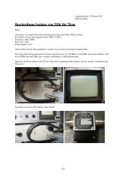
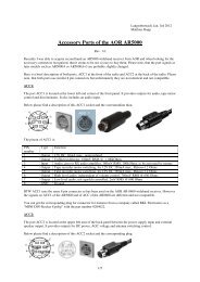
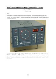
Langenbrettach, Jan. 5th 2012Matthias BoppAutomatic Antenna Switch for the <strong>AOR</strong> AR5000Rev. 1.0Recently I was able to acquire second hand an AR5000 wideband receiver and wanted to extend the number ofantenna ports from originally 2 to 4 ports.This is exactly what the optional antenna switching unit supplied from <strong>AOR</strong> is providing. It is connected to ANT1 and the control switching signal is taken from ACC 2. ANT 2 is left unaffected and available for connection toan aerial leaving the <strong>AS5000</strong> to provide access to ANT 1, ANT 3 and ANT 4. A detailed description of theACC2 port and its signals can be found in another document provided on my website.Switching can be accomplished automatically using a user defined form of band plan (frequency bandsassociated with each antenna port) or manually from the ANT select menu.Here is the truth table for the antenna switching unit:Antenna port ANT SW A ANT SW BANT 1 High HighANT 3 Low HighANT 4 Low LowBelow find the <strong>AS5000</strong> circuit diagram. ANT SW A (PIN 5 of ACC2) is the yellow wire, ANT SW B (PIN 6 ofACC2) is the blue wire, the red wire is +12V DC (PIN 1 of ACC2). Ground (PIN 8 of ACC2) and shield areconnected1/9
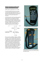
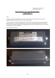
Here are some more detailed pictures of the AS-5000 including a view inside:In the AS-5000 device 2 antenna relays are cascaded and thus the specification in terms of insertion loss andisolation varies for the different ports:Insertion loss:ANT1 to COM 1 dB max.ANT3 to COM 1.5 dB max.Isolation:ANT1 to ANT3 40 dB min.ANT1 to ANT4 50 dB min.All data is specified at a test frequency of 1GHz.A friend measured his AS-5000 and got the following results for ANT1 to COM, which are well within the givenspecifications:Frequency / GHz Insertion Loss /dB0.5 0.51.0 0.91.5 1.51.8 1.62.2 1.92.5 2.12/9
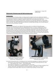
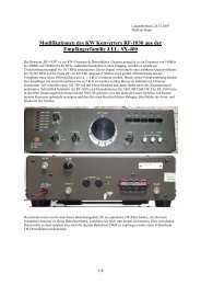
As decided to build a similar device like AS-5000 myself and add the capability, to supply the AGC voltage(available at ACC2) to a special connector. I also wanted to improve the insertion loss especially up to 1.3 GHzand as I had some small RF capable relays I wanted to give them a try. They are Series 712 TO-5 DPDT-relaysfrom Teledyne and I found them in a surplus test equipment. I will attach a copy of its specification to the end ofthis document. They seemed to fit perfectly as they operate with +12V DC and 25mA and the ACC2 portsupplies +12V DC with 50 mA max.This is a draft schematic showing my setup. Please note that it is not to scale. The RF connections which are notusing semi-rigid coaxial cables have to be kept very short.3/9
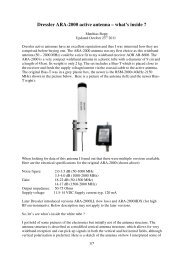
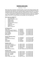
Here are some more pictures of my AS-5000 clone taken during its assembly and when finished:Well, now the question comes: how does the clone perform. I made some course measurements with a noisesource and spectrum analyzer.The three measurements show the insertion loss from COM to ANT1, COM to ANT3 and COM to ANT4.Horizontal scaling is 300 MHz per division (0 to 3 GHz total horizontal axis), vertical scaling is 1 dB perdivision (10 dB total vertical axis). The yellow curve is always the reference measurement without the antennaswitcher inserted, the blue is the respective curve with the antenna switcher plugged in.4/9
COM to ANT1COM to ANT35/9
COM to ANT4As can be seen the insertion loss up to 1 GHz is below 0.5 dB on all three ports respectively below 1 dB up to1.3 GHz. The insertion loss between 1.5 GHz and 2.4 GHz is increasing strongly with some resonances.Between 2.4 and 2.5 GHz the switch has an insertion loss of maximum 1.5 dB on all three ports.Frequency / GHz Insertion Loss /dB0.5
7/9
8/9
9/9