fixed or semi-fixed foam fire protection systems for storage tanks - NIFV
fixed or semi-fixed foam fire protection systems for storage tanks - NIFV
fixed or semi-fixed foam fire protection systems for storage tanks - NIFV
- No tags were found...

You also want an ePaper? Increase the reach of your titles
YUMPU automatically turns print PDFs into web optimized ePapers that Google loves.
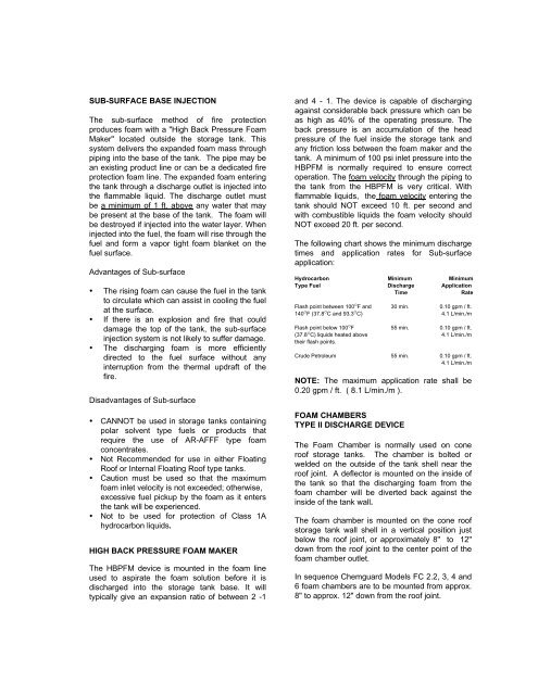
SUB-SURFACE BASE INJECTIONThe sub-surface method of <strong>fire</strong> <strong>protection</strong>produces <strong>foam</strong> with a "High Back Pressure FoamMaker" located outside the st<strong>or</strong>age tank. Thissystem delivers the expanded <strong>foam</strong> mass throughpiping into the base of the tank. The pipe may bean existing product line <strong>or</strong> can be a dedicated <strong>fire</strong><strong>protection</strong> <strong>foam</strong> line. The expanded <strong>foam</strong> enteringthe tank through a discharge outlet is injected intothe flammable liquid. The discharge outlet mustbe a minimum of 1 ft. above any water that maybe present at the base of the tank. The <strong>foam</strong> willbe destroyed if injected into the water layer. Wheninjected into the fuel, the <strong>foam</strong> will rise through thefuel and f<strong>or</strong>m a vap<strong>or</strong> tight <strong>foam</strong> blanket on thefuel surface.Advantages of Sub-surface• The rising <strong>foam</strong> can cause the fuel in the tankto circulate which can assist in cooling the fuelat the surface.• If there is an explosion and <strong>fire</strong> that coulddamage the top of the tank, the sub-surfaceinjection system is not likely to suffer damage.• The discharging <strong>foam</strong> is m<strong>or</strong>e efficientlydirected to the fuel surface without anyinterruption from the thermal updraft of the<strong>fire</strong>.Disadvantages of Sub-surface• CANNOT be used in st<strong>or</strong>age <strong>tanks</strong> containingpolar solvent type fuels <strong>or</strong> products thatrequire the use of AR-AFFF type <strong>foam</strong>concentrates.• Not Recommended f<strong>or</strong> use in either FloatingRoof <strong>or</strong> Internal Floating Roof type <strong>tanks</strong>.• Caution must be used so that the maximum<strong>foam</strong> inlet velocity is not exceeded; otherwise,excessive fuel pickup by the <strong>foam</strong> as it entersthe tank will be experienced.• Not to be used f<strong>or</strong> <strong>protection</strong> of Class 1Ahydrocarbon liquids.HIGH BACK PRESSURE FOAM MAKERThe HBPFM device is mounted in the <strong>foam</strong> lineused to aspirate the <strong>foam</strong> solution bef<strong>or</strong>e it isdischarged into the st<strong>or</strong>age tank base. It willtypically give an expansion ratio of between 2 -1and 4 - 1. The device is capable of dischargingagainst considerable back pressure which can beas high as 40% of the operating pressure. Theback pressure is an accumulation of the headpressure of the fuel inside the st<strong>or</strong>age tank andany friction loss between the <strong>foam</strong> maker and thetank. A minimum of 100 psi inlet pressure into theHBPFM is n<strong>or</strong>mally required to ensure c<strong>or</strong>rectoperation. The <strong>foam</strong> velocity through the piping tothe tank from the HBPFM is very critical. Withflammable liquids, the <strong>foam</strong> velocity entering thetank should NOT exceed 10 ft. per second andwith combustible liquids the <strong>foam</strong> velocity shouldNOT exceed 20 ft. per second.The following chart shows the minimum dischargetimes and application rates f<strong>or</strong> Sub-surfaceapplication:Hydrocarbon Minimum MinimumType Fuel Discharge ApplicationTimeRateFlash point between 100 o F and 30 min. 0.10 gpm / ft.140 o F (37.8 o C and 93.3 o C) 4.1 L/min./mFlash point below 100 o F 55 min. 0.10 gpm / ft.(37.8 o C) liquids heated above 4.1 L/min./mtheir flash points.Crude Petroleum 55 min. 0.10 gpm / ft.4.1 L/min./mNOTE: The maximum application rate shall be0.20 gpm / ft. ( 8.1 L/min./m ).FOAM CHAMBERSTYPE II DISCHARGE DEVICEThe Foam Chamber is n<strong>or</strong>mally used on coneroof st<strong>or</strong>age <strong>tanks</strong>. The chamber is bolted <strong>or</strong>welded on the outside of the tank shell near theroof joint. A deflect<strong>or</strong> is mounted on the inside ofthe tank so that the discharging <strong>foam</strong> from the<strong>foam</strong> chamber will be diverted back against theinside of the tank wall.The <strong>foam</strong> chamber is mounted on the cone roofst<strong>or</strong>age tank wall shell in a vertical position justbelow the roof joint, <strong>or</strong> approximately 8" to 12"down from the roof joint to the center point of the<strong>foam</strong> chamber outlet.In sequence Chemguard Models FC 2.2, 3, 4 and6 <strong>foam</strong> chambers are to be mounted from approx.8" to approx. 12" down from the roof joint.