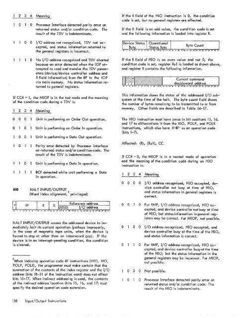
2 3 4 Meaningoo Processor Interface detected parity error onreturned status and/or condition code. <strong>The</strong>result of the TDY is indeterminate.If the R field of the HIO instruction is 0, the conditioncode is set, but no general registers are affected.If the R field is an odd value, the condition code is setand the following information is loaded into register R.o 0I/O address not recognized, TDY not accepted,and status information returned tothe general registers is incorrect.o No I/o address recognized and TDY abortedbecause an error detected when the lOP attemptedto read and transfer the TDY parameters(device/device controller address andR field information) from the BP to the lOPvia main memory. No status information returnedto general registers.If CC4 = 1, the MIOP is in the test mode and the meaningof the condition code during a TDY is:2 3 4 Meaning0 0 0 Unit is performing an Order Out operation.0 0 Unit is performing an Order In operation.HIO0 0 Unit is performing a Data Out operation.0 Parity error detected by Processor Interfaceon returned status and/or condition code. <strong>The</strong>result of the TDY is indeterminate.0 Unit is performing a Data In operation.BCF detected while unit performing a DataIn operati on.HAL T INPUT/OUTPUT0/Vord index alignment, t privileged)HALT INPUT/OUTPUT causes the addressed device to immediatelyhalt its current operation (perhaps improperly,in the case of magnetic tape units, when the device isforced to stop at other than an i nterrecord gap). If thedevice is in an interrupt-pending condition, the conditionis cleared.tWhen indexing operation code 4F instructions (HIO; RIO;POLP, POLR), the programmer must make certain that thesummation of the contents of the index register and the I/oaddress (bits 18-31 of the instruction word) does not affectbits 15-17. When indirect addressing is used, the contentsof the indirect address location (bits 15, 16, and 17) mustspecify the desired operation code extension.If the R field of HIO is an even value and not 0, thecondition code is set, register Ru 1 is loaded as shown above,and register R contains the following information.This information shows the status of the addressed I/O sub<strong>system</strong>at the time of the halt. <strong>The</strong> byte count field showsthe number of bytes remaining to be transmitted to or frommemory. Other fields are described in Table 14-17.<strong>The</strong> HIO instruction must have zeros in bit positions 15, 16,and 17 to differentiate it from the RIO, POLP, and POLRinstructions, which also have X'4F' as an operation code(bits 1-7).Affected: (R), (Ru1), CCIf CC4 = 0, the MIOP is in a normal mode of operationand the meaning of the condition code during an HIOinstruction is:2 3 4 Meaningo 0 0 0 I/O address recognized, HIO accepted, devicecontroller not busy at time of HIO,and status information in general registers iscorrect.o 0 0 For R.MP, I/O address recognized, HIO ac=ooo 0cepted, and device controller not busy at timeof HIO; but status information ingeneral registersmay be correct. For MIOP, not possible.I/O address recognized, HIO accepted, anddevice controller busy at the time of the HIO,and status i nformati on is correct.o For RMP, I/O address recognized, HIO accepted,and device controller busy at the timeof the HIO; but the status information in thegeneral registers may be incorrect. For MIOP,not pO$5ible.o 0 0 Not possible.o 0 Processor Interface detected parity error onreturned status and/or condi ti on code. <strong>The</strong>result of the HIO is indeterminate.138 Input/Output Instructions
2 3 4 Meaningo 0 I/o address not recognized, HIO not accepted,and no status i nformati on returned togeneral registers.o No I/O address recognized and HIO abortedbecause an error detected when the lOP attemptedto read and transfer the HIO parameters(device/device controller address andR field information) from the BP to the lOP.No status information returned to generalregisters.If CC4 = 1, the MIOP is in the test mode and the meaningof the condition code during an HIO is:2 3 4 Meaningo 0 0 Unit is performing an Order Out operation.ooo 0ooUnit is performing an Order In operation.Unit is performing a Data Out operation.Processor Interface detected parity error onreturned status and/or condition code. <strong>The</strong>result of the HIO is indeterminate.Unit is performing a Data In operation.BCF detected while unit performing a DataIn operati on.RF~FT TNPIIT /()IITPIIT0N~~d i~de~ '~Iig~~e~i, t privileged)contains either a BP, MIOP, and/or-RMP). Unit addressesX 101_X 15 1 may be assigned to processors within the cluster.Unit address X'5 1 in cluster XIO I is reserved for the BP. Unitaddress X'6 1 is assigned always to the MI and unit addressX?I is assigned always to the PI for all clusters.Status information is returned only in the condition codebits. <strong>The</strong> R field is not used.Affected: CC1, CC2, CC3Condition code settings are as shown below:2 3 4 Meaningo 0 0 - I/O address recognized.POLPo -I/O address not recognized.POLL PROCESSOR(Word index alignment, t privileged)POLL PROCESSOR causes the addressed unit to return unitfau I t status in bi ts 16-31 of reg i ster Rtt. Th i s status i nformationis unit dependent (see Appendix C, Table C-1).In addition to the operation code of X'4F' I bits 15, 16,and 17 must be coded as 010, respectively.Affected: (R), CC1, CC2, CC~Condition Code settings are as shown below:RESET INPUT/OUTPUT causes the selected lOP to generatean I/O reset signal to all devices attached to it. In additionto the operation code X'4F', bits 15, 16, and 17 mustbe coded as 001, respectively.An RIO instruction resets the selected unit in the samemanner as ZCRIO on the operator's control console. However,unlike the control command, the RIO instructionresets only the addressed unit and may be controlled bythe executing program. Since the BP may be addressed asan lOP, it wi II accept an RIO instruction that causes theBP to reset itself in the same manner as ZCRBP. (Note thatthis procedure is not normal practice.)C luster addresses (CA), bit positions 18-20, may have valuesof XIOI_X?I. Cluster addresses X'0'-X ' 6 1 may be assignedto any cluster containing processors (i .e., BP, MIOP, and/or RMP). In a monoprocessor <strong>system</strong>, cluster address XIO Iis assi.gned to the c luster containing the basic processor(BP). Cluster address X?I is assigned only to the clustercontaining a <strong>system</strong> processor. If CA equals X?I I the UAfield is reserved. Unit addresses (UA), bit positions 21-23,may have values of XIOI_X?I. Unit addresses are requiredonly if the cluster address is X'0'_X '6 1 , (i.e., cluster2 3 4 Result of POLPo 0 0 - Processor fault interrupt not pending.o 0 - Processor fault interrupt pending.POLRo ~Unit address not recognized.POLL AND RESET PROCESSOR(Word index alignment, t privileged)POLL AND RESET PROCESSOR causes the selected unit toreturn unit fault status in bits 16 to 31 of register Rtt andresets the unit's fault status register. This status informationis unit dependent (see Appendix C, Table C-1).tSee footnote to HIO instruction.ttThis fault status is duplicated in bits 0 to 15 of register R.Input/Output Instru ctions 139
- Page 1 and 2:
Xerox 560 ComputerReference Manual9
- Page 5 and 6:
4. INPUT/OUTPUT OPERA TIO NS 142 AG
- Page 7 and 8:
1. XEROX 560 COMPUTER SYSTEMINTRODU
- Page 10 and 11:
Many operations are performed in fl
- Page 12 and 13:
Rapid Context Switching. When respo
- Page 14 and 15:
2. SYSTEM ORGANIZATIONThe elements
- Page 16:
FAST MEMORYARITHMETIC AND CONTROL U
- Page 19 and 20:
INFORMATION BOUNDARIESBasic process
- Page 21 and 22:
(Maximumof eight)Core Core Core Cor
- Page 23 and 24:
3. Diagnostic logic. Each memory dr
- Page 25 and 26:
eference address field of the instr
- Page 27 and 28:
Instruction in memory:Instruction i
- Page 29 and 30:
Real-extended addressing is specifi
- Page 31:
Table 1. Basic Processor Operating
- Page 35 and 36:
DesignationFunctionDesignationFunct
- Page 37 and 38:
InterruptStateDisarmedArmed[$Waitin
- Page 39 and 40:
AddressTable 2. Interrupt Locations
- Page 41 and 42:
is assumed to contain an XPSD or a
- Page 43 and 44:
Table 3. Summary of Trap LocationsL
- Page 45 and 46:
TRAP MASKSThe programmer may mask t
- Page 47 and 48:
PUSH-DOWN STACK LIMIT TRAPPush-down
- Page 49 and 50:
Instruction Name Mnemonic FaultDeci
- Page 51 and 52:
subroutine. However, with certain c
- Page 53 and 54:
3. INSTRUCTION REPERTOIREThis chapt
- Page 55 and 56:
CC1 is unchanged by the instruction
- Page 57 and 58:
Condition code settings:2 3 4 Resul
- Page 59 and 60:
Example 2, odd R field value:Before
- Page 61 and 62:
significance (FS), floating zero (F
- Page 63 and 64:
next sequential register after regi
- Page 65 and 66:
R 1 R2 R3 MeaningoThe effective vir
- Page 67 and 68:
Condition code settings:2 3 4 Resul
- Page 69 and 70:
MIMULTIPLY IMMEDIATE(Immediate oper
- Page 71 and 72:
original contents of register R, re
- Page 73 and 74:
Instruction NameCompare HalfwordMne
- Page 75 and 76:
Condition code settings:2 3 4 Resul
- Page 77 and 78:
2 3 4 Result of ShiftCircular Shift
- Page 79 and 80:
4. At the completion of the left sh
- Page 81 and 82:
Instruction NameFloating Subtract L
- Page 83 and 84:
The following table shows the possi
- Page 85 and 86:
Table 8.Condition Code Settings for
- Page 87 and 88:
PACKED DECIMAL NUMBERSAll decimal a
- Page 89 and 90:
DSTDECIMAL STORE(Byte index alignme
- Page 91 and 92:
If no indirect addressing or indexi
- Page 93 and 94: Instruction NameMnemonicDesignation
- Page 95 and 96: Both byte strings are C bytes in le
- Page 97 and 98: of the destination byte that caused
- Page 99 and 100: again present, unti I a positive or
- Page 101 and 102: The new contents of register 7 are:
- Page 103 and 104: traps to location X'42 1 as a resul
- Page 105 and 106: If there is sufficient space in the
- Page 107 and 108: If CC1, or CC3, or both CC1 and CC3
- Page 109 and 110: appropriate memory stack locations
- Page 111 and 112: II, EI) are generated by II ORing"
- Page 113 and 114: In the real extended addressing mod
- Page 115 and 116: CAll INSTRUCTIONSEach ofthe four CA
- Page 117 and 118: The XPSD instruction' is used for t
- Page 119 and 120: If (I)1O = 0, trap or interrupt ins
- Page 121 and 122: For either memory map format and ei
- Page 123 and 124: initial value plus the initial valu
- Page 125 and 126: Table 9. Status Word 0Field Bits Co
- Page 127 and 128: READ INTERRUPT INHIBITSThe followin
- Page 129 and 130: Table 11.Read Direct Mode 9 Status
- Page 131 and 132: SET ALARM INDICATORThe following co
- Page 133 and 134: INPUT jOUTPUT INSTRUCTIONSThe I/o i
- Page 135 and 136: Table 13.Description of I/o Instruc
- Page 137 and 138: Table 15.Device Status Byte (Regist
- Page 139 and 140: Table 16. Operational Status Byte (
- Page 141 and 142: Table 19.Status Response Bits for A
- Page 143: If CC4 = 0, the MIOP is in a normal
- Page 147 and 148: The functions of bits within the DC
- Page 149 and 150: 4. Each unit-record controller (int
- Page 151 and 152: Interrupt at Channel End (Bit Posit
- Page 153 and 154: Transfer in Channel. A control lOCO
- Page 155 and 156: Otherwise, the first word of the ne
- Page 157 and 158: Depending upon the characteristics
- Page 159 and 160: change the rate on the primary cons
- Page 161 and 162: Location(hex) (dec)20 3221 3322 342
- Page 163 and 164: Table 22.Diagnostic Control (P-Mode
- Page 165 and 166: at its normal rate (e. g., fixed du
- Page 167 and 168: SET LOW CLOCK MARGINSThis command c
- Page 169 and 170: BP STATUS AND NO.Th i s group of i
- Page 171 and 172: Input5MPri ntout5MFunctionStore X 1
- Page 173 and 174: 6. SYSTEM CONFIGURATION CONTROLPool
- Page 175 and 176: Table 25. Functions of Processor Cl
- Page 177: Table 26. Functions of Memory Unit
- Page 180 and 181: STANDARD 8-BIT COMPUTER CODES (EBCD
- Page 182 and 183: STANDARD SYMBOL-CODE CORRESPONDENCE
- Page 184 and 185: STANDARD SYMBOL-CODE CORRESPONDENCE
- Page 186 and 187: TABLE OF POWERS OF SIXTEEN II162564
- Page 188 and 189: HEXADECIMAL-DECIMAL INTEGER CONVERS
- Page 190 and 191: HEXADECIMAL-DECIMAL INTEGER CONVERS
- Page 192 and 193: HEXADECIMAL-DECIMAL INTEGER CONVERS
- Page 194 and 195:
HEXADECIMAL-DECIMAL FRACTION CONVER
- Page 196 and 197:
HEXADECIMAL-DECIMAL FRACTION CONVER
- Page 198 and 199:
APPENDIX B.GLOSSARY OF SYMBOLIC TER
- Page 200 and 201:
TermMeaningTermMeaningWKxWrite key
- Page 202 and 203:
Table C-2. Memory Unit Status Regis
- Page 204 and 205:
Y OYf'lV r'f'lrnf'lrtil"\n'''' ....
- Page 206:
701 South Aviation BoulevardEI Segu