New: One-piece horn with - W1GHZ
New: One-piece horn with - W1GHZ
New: One-piece horn with - W1GHZ

You also want an ePaper? Increase the reach of your titles
YUMPU automatically turns print PDFs into web optimized ePapers that Google loves.
Feed Radiation PatternDual-mode 10&24 GHz feed at 24 GHz, no <strong>horn</strong>Figure 2E-plane0 dB -10 -20 -30H-planeDish diameter = 37 λ Feed diameter = 0.5 λFeed Phase Angle90E-plane67.5H-plane4522.50-22.5-45-67.5-900 10 20 30 40 50 60 70 80 90Rotation Angle around specifiedPhase Center = 0.1 λ beyond apertureParabolic Dish Efficiency %9080706050403020MAX Possible Efficiency <strong>with</strong> Phase errorMAX Efficiency <strong>with</strong>out phase error AFTER LOSSES:REAL WORLD at least 15% lowerIlluminationSpilloverFeed Blockage1 dB2 dB3 dB4 dB5 dB6 dB7 dB8 dB100.25 0.3 0.4 0.5 0.6 0.7 0.8 0.9 1.0Parabolic Dish f/D<strong>W1GHZ</strong> 1998, 2002
Feed Radiation PatternDual-mode 10&24 GHz feed at 10.368 GHz, no <strong>horn</strong>Figure 3E-plane0 dB -10 -20 -30H-planeDish diameter = 15.8 λ Feed diameter = 0.5 λFeed Phase Angle90E-plane67.5H-plane4522.50-22.5-45-67.5-900 10 20 30 40 50 60 70 80 90Rotation Angle around specifiedPhase Center = 0 λ beyond apertureParabolic Dish Efficiency %9080706050403020MAX Possible Efficiency <strong>with</strong> Phase errorMAX Efficiency <strong>with</strong>out phase error AFTER LOSSES:REAL WORLD at least 15% lowerIlluminationSpilloverFeed Blockage1 dB2 dB3 dB4 dB5 dB6 dB7 dB8 dB100.25 0.3 0.4 0.5 0.6 0.7 0.8 0.9 1.0Parabolic Dish f/D<strong>W1GHZ</strong> 1998, 2002
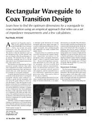
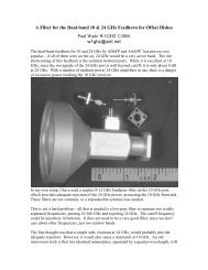
The other mechanical problem is robust feedline attachment: WR-42 waveguide for 24GHz and an SMA connector for 10 GHz. Using brass or copper for the feed<strong>horn</strong> wouldallow soldering, but both are heavy and expensive. Turning the feed from aluminum rodwas the best choice, but the size would have to be large enough for the WR-42 holepattern: 7/8” square, or 1.25 inch diameter.Figure 4I found that 1” square aluminum was readily available in short lengths, so I orderedsome, along <strong>with</strong> a ¾” 60º countersink. After a couple of hours <strong>with</strong> the lathe, my firstattempt is shown in Figure 4. The machining was possible, but the ¾” countersinkdiameter is smaller than the 20.4 mm inner diameter that a small shoulder was left. Ifiddled <strong>with</strong> a boring bar to minimize the shoulder so that I could at least measure theVSWR and make sure I was on the right track.Some improvement was necessary to make a proper taper. Matt, KB1VC, attempted tomake a custom cutting tool, but the results were not encouraging – the countersink isclearly the right tool. I went back to the MSC catalog and found a 7/8” countersink,slightly oversized. The HSS tool steel is too hard to cut <strong>with</strong> ordinary tooling, so I used atoolpost grinder to grind the countersink to the exact 20.4 mm diameter. Now we areable to machine the correct taper cleanly.
The basic machining procedure is:1. Cut a <strong>piece</strong> of 1” square aluminum to about 2.6” long.2. True up in 4-jaw chuck and face ends.3. Drill a hole about ¼” diameter down the center, all the way through.4. Drill ¾” diameter about 35 mm deep.5. Bore out to 20.4 mm diameter. This leaves a small shoulder at the taper.6. Countersink <strong>with</strong> 20.4 mm, 60º countersink to form the taper.7. Turn down outside diameter to leave about 1 mm wall, about 16 mm long.8. Trim end to leave output section length of 35.4 mm.9. Drill out circular waveguide diameter to 9.2 mm diameter.10. Mark out WR-42 holes in back end, drill and tap 4-40 thread.11. Mark out and drill SMA holes in one side, <strong>with</strong> center 29.3 mm from open end.12. Tap mounting holes for SMA 2-56 thread.13. Clean up and degrease.14. Fit SMA.The countersink setup on the lathe is shown below:
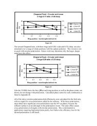
Corrugated <strong>horn</strong>sThe four corrugated <strong>horn</strong>s I have ready to try are shown in Figure 5. I simulated thefeed<strong>horn</strong> <strong>with</strong> each of these, as well as <strong>with</strong> a plain conical <strong>horn</strong>. Patterns and calculatedefficiencies are shown in the following figures at 24 GHz, and at 10 GHz <strong>with</strong> the phasecenter at the best location for 24 GHz:• Figure 6 – plain conical <strong>horn</strong>• Figure 7 – RCA DSS <strong>horn</strong>• Figure 8 – Chaparral 11 GHz offset feed<strong>horn</strong>• Figure 9 – <strong>horn</strong> from CD-80 dish (0.8m, f/D = 0.8)• Figure 10 – surplus corrugated <strong>horn</strong>
Dual-mode 10&24 feed <strong>with</strong> 64mm conical <strong>horn</strong> at 24 GHzFigure 6a0 dB -10-20 -30E-planeH-planeFeed Radiation PatternDish diameter = 37 λ Feed diameter = 1 λ9067.54522.50-22.5-45-67.5Feed Phase Angle-90E-planeH-plane0 10 20 30 40 50 60 70 80 90Rotation Angle around specifiedPhase Center = 2.1 λ inside aperture9080706050403020MAX Possible Efficiency <strong>with</strong> Phase errorMAX Efficiency <strong>with</strong>out phase error AFTER LOSSES:REAL WORLD at least 15% lowerIlluminationSpilloverFeed Blockage1 dB2 dB3 dB4 dB5 dB6 dB7 dB8 dBParabolic Dish Efficiency %100.25 0.3 0.4 0.5 0.6 0.7 0.8 0.9 1.0Parabolic Dish f/D<strong>W1GHZ</strong> 1998, 2002Dual-mode 10&24 feed <strong>with</strong> 64mm conical <strong>horn</strong> at 10.368 GHzFigure 6b0 dB -10-20 -30E-planeH-planeFeed Radiation PatternDish diameter = 15.8 λ Feed diameter = 0.5 λ9067.54522.50-22.5-45-67.5Feed Phase Angle-90E-planeH-plane0 10 20 30 40 50 60 70 80 90Rotation Angle around specifiedPhase Center = 0.9 λ inside aperture9080706050403020MAX Possible Efficiency <strong>with</strong> Phase errorMAX Efficiency <strong>with</strong>out phase error AFTER LOSSES:REAL WORLD at least 15% lowerIlluminationSpilloverFeed Blockage1 dB2 dB3 dB4 dB5 dB6 dB7 dB8 dBParabolic Dish Efficiency %100.25 0.3 0.4 0.5 0.6 0.7 0.8 0.9 1.0Parabolic Dish f/D<strong>W1GHZ</strong> 1998, 2002
Dual-mode 10&24 feed <strong>with</strong> RCA DSS <strong>horn</strong> at 24 GHzFigure 7a0 dB -10-20 -30E-planeH-planeFeed Radiation PatternDish diameter = 37 λ Feed diameter = 1 λ9067.54522.50-22.5-45-67.5Feed Phase Angle-90E-planeH-plane0 10 20 30 40 50 60 70 80 90Rotation Angle around specifiedPhase Center = 2 λ inside aperture9080706050403020MAX Possible Efficiency <strong>with</strong> Phase errorMAX Efficiency <strong>with</strong>out phase error AFTER LOSSES:REAL WORLD at least 15% lowerIlluminationSpilloverFeed Blockage1 dB2 dB3 dB4 dB5 dB6 dB7 dB8 dBParabolic Dish Efficiency %100.25 0.3 0.4 0.5 0.6 0.7 0.8 0.9 1.0Parabolic Dish f/D<strong>W1GHZ</strong> 1998, 2002Dual-mode 10&24 feed <strong>with</strong> RCA DSS <strong>horn</strong> at 10.368 GHzFigure 7b0 dB -10-20 -30E-planeH-planeFeed Radiation PatternDish diameter = 15.8 λ Feed diameter = 0.5 λ9067.54522.50-22.5-45-67.5Feed Phase Angle-90E-planeH-plane0 10 20 30 40 50 60 70 80 90Rotation Angle around specifiedPhase Center = 0.86 λ inside aperture9080706050403020MAX Possible Efficiency <strong>with</strong> Phase errorMAX Efficiency <strong>with</strong>out phase error AFTER LOSSES:REAL WORLD at least 15% lowerIlluminationSpilloverFeed Blockage1 dB2 dB3 dB4 dB5 dB6 dB7 dB8 dBParabolic Dish Efficiency %100.25 0.3 0.4 0.5 0.6 0.7 0.8 0.9 1.0Parabolic Dish f/D<strong>W1GHZ</strong> 1998, 2002
Dual-mode 10&24 feed <strong>with</strong> Chaparall offset <strong>horn</strong> at 24 GHzFigure 8a0 dB -10-20 -30E-planeH-planeFeed Radiation PatternDish diameter = 37 λ Feed diameter = 1 λ9067.54522.50-22.5-45-67.5Feed Phase Angle-90E-planeH-plane0 10 20 30 40 50 60 70 80 90Rotation Angle around specifiedPhase Center = 1.9 λ inside aperture9080706050403020MAX Possible Efficiency <strong>with</strong> Phase errorMAX Efficiency <strong>with</strong>out phase error AFTER LOSSES:REAL WORLD at least 15% lowerIlluminationSpilloverFeed Blockage1 dB2 dB3 dB4 dB5 dB6 dB7 dB8 dBParabolic Dish Efficiency %100.25 0.3 0.4 0.5 0.6 0.7 0.8 0.9 1.0Parabolic Dish f/D<strong>W1GHZ</strong> 1998, 2002Dual-mode 10&24 feed <strong>with</strong> Chaparall offset <strong>horn</strong> at 10.368 GHzFigure 8b0 dB -10-20 -30E-planeH-planeFeed Radiation PatternDish diameter = 15.8 λ Feed diameter = 0.5 λ9067.54522.50-22.5-45-67.5Feed Phase Angle-90E-planeH-plane0 10 20 30 40 50 60 70 80 90Rotation Angle around specifiedPhase Center = 0.816 λ inside aperture9080706050403020MAX Possible Efficiency <strong>with</strong> Phase errorMAX Efficiency <strong>with</strong>out phase error AFTER LOSSES:REAL WORLD at least 15% lowerIlluminationSpilloverFeed Blockage1 dB2 dB3 dB4 dB5 dB6 dB7 dB8 dBParabolic Dish Efficiency %100.25 0.3 0.4 0.5 0.6 0.7 0.8 0.9 1.0Parabolic Dish f/D<strong>W1GHZ</strong> 1998, 2002
Dual-mode 10&24 feed <strong>with</strong> CD-80 corrugated <strong>horn</strong> at 24 GHzFigure 9a0 dB -10-20 -30E-planeH-planeFeed Radiation PatternDish diameter = 37 λ Feed diameter = 1 λ9067.54522.50-22.5-45-67.5Feed Phase Angle-90E-planeH-plane0 10 20 30 40 50 60 70 80 90Rotation Angle around specifiedPhase Center = 2.35 λ inside aperture9080706050403020MAX Possible Efficiency <strong>with</strong> Phase errorMAX Efficiency <strong>with</strong>out phase error AFTER LOSSES:REAL WORLD at least 15% lowerIlluminationSpilloverFeed Blockage1 dB2 dB3 dB4 dB5 dB6 dB7 dB8 dBParabolic Dish Efficiency %100.25 0.3 0.4 0.5 0.6 0.7 0.8 0.9 1.0Parabolic Dish f/D<strong>W1GHZ</strong> 1998, 2002Dual-mode 10&24 feed <strong>with</strong> CD-80 corrugated <strong>horn</strong> at 10 GHzFigure 9b0 dB -10-20 -30E-planeH-planeFeed Radiation PatternDish diameter = 15.8 λ Feed diameter = 0.5 λ9067.54522.50-22.5-45-67.5Feed Phase Angle-90E-planeH-plane0 10 20 30 40 50 60 70 80 90Rotation Angle around specifiedPhase Center = 1.01 λ inside aperture9080706050403020MAX Possible Efficiency <strong>with</strong> Phase errorMAX Efficiency <strong>with</strong>out phase error AFTER LOSSES:REAL WORLD at least 15% lowerIlluminationSpilloverFeed Blockage1 dB2 dB3 dB4 dB5 dB6 dB7 dB8 dBParabolic Dish Efficiency %100.25 0.3 0.4 0.5 0.6 0.7 0.8 0.9 1.0Parabolic Dish f/D<strong>W1GHZ</strong> 1998, 2002
The calculated efficiencies and phase centers are summarized in the table below. At 10GHz, efficiencies are listed at the 24 GHz P.C. (phase center) as well as the optimum,assuming that the feed position would be more critical at 24 GHz. Phase centers aremeasured from the center of the aperture; negative numbers are inside the <strong>horn</strong>.Dual band 10&24 GHz Feed - Calculated Horn Performance24 GHz 10 GHz Offset f/D = 0.7at 24 GHz P.C.HORN Efficiency f/D Ph. Cen. Efficiency f/D Ph. Cen. 24 GHz 10 GHznone 76% 0.72 1.2 mm 71% 0.38 0 mm 76% 47%Conical 76% 0.8 -26 67% 0.7 -31.2 74% 66%RCA 75% 0.93 -24.8 77% 0.7 -5.8 69% 68%Chaparral 78% 0.81 -23.6 75% 0.65 -24.9 76% 74%CD-80 77% 0.88 -29.1 78% 0.76 -4.9 68% 65%Surplus 79% 0.8 -6.2 76% 0.7 -22 77% 70%All of the <strong>horn</strong>s improve the performance at 10 GHz while maintaining high efficiency at24 GHz. However, the best f/D and the phase centers for the two bands are not the same.The best choice appears to be the Chaparral <strong>horn</strong>, <strong>with</strong> phase center differing by only 1.3mm, so that the optimum position for 24 GHz is only 0.04λ off at 10 GHz. The result isexcellent calculated efficiency for both bands, 76% at 24 GHz and 74% at 10.368 GHz.This is comparable to the best single band feeds – a dual-band feed that does notcompromise performance.PerformanceThe temperature in <strong>New</strong> England is considerably below freezing, and the sun will not behigh enough for sun noise measurements until well after the deadline for this paper. Ihope to have some results before you read this.Thus, the only testing so far is for VSWR. At 10.368 GHz, the VSWR is about 1.25 <strong>with</strong>no tuning. At 24.192 GHz, the VSWR is about 2.5 <strong>with</strong> the circular waveguideconnected directly to WR-42 rectangular waveguide. This was predicted in simulation,since the characteristic impedance of circular waveguide is different from rectangularguide. A matching section, shown in Figure 11, was simulated and optimized; it is aquarter-wavelength section of rectangular guide <strong>with</strong> the dimensions chosen to providethe required impedance to match the circular guide to WR-42. To make machiningeasier, a radius was added at the corners, and increased until the ends are simply ¼ inchdiameter; a slight increase in the wide dimension was required for the same impedance.The matching section improves the measured VSWR to about 1.05. I believe European24 GHz operation is at 24.048 GHz; VSWR there is about 1.04. Adding the variouscorrugated <strong>horn</strong>s to the basic feed has only a small effect on the VSWR on either band.
ConclusionThe dual-band feed<strong>horn</strong> for 10 and 24 GHz by AD6FP and AA6IW looks verypromising, and should provide excellent offset-dish performance on both bands. I havemade some small improvements to make construction easier and more robust, and plan tohave one on the air as soon as warm weather returns.References:1. Gary Lauterbach, AD6FP, and Lars Karlsson, AA6IW, “Dual-Band 10/24 GHzFeed<strong>horn</strong>s for Shallow Dishes,” Proceedings of Microwave Update 2001, ARRL,2001, pp. 181-190.2. Al Ward, W5LUA, “Dual Band Feed<strong>horn</strong>s for 2304/3456 MHz and 5760/10368MHz,” Proceedings of Microwave Update 1997, ARRL, 1997, pp. 158-163.3. Joel Harrison, W5ZN, “W5ZN Dual Band 10 GHz / 24 GHz Feed<strong>horn</strong>,”Proceedings of Microwave Update 1998, ARRL, 1998, pp. 189-190.4. Joel Harrison, W5ZN, “Further Evaluation of the W5LUA & W5ZN Dual BandFeeds,” Proceedings of Microwave Update 1999, ARRL, 1999, pp. 66-73.5. R.H. Turrin, (W2IMU), “Dual Mode Small-Aperture Antennas,” IEEETransactions on Antennas and Propagation, AP-15, March 1967, pp. 307-308.(reprinted in A.W. Love, Electromagnetic Horn Antennas, IEEE, 1976, pp. 214-215.)6. www.mscdirect.com7. www.ansoft.com