LED X Deck Lights Installation Guide - Code 3 Public Safety ...
LED X Deck Lights Installation Guide - Code 3 Public Safety ...
LED X Deck Lights Installation Guide - Code 3 Public Safety ...

Create successful ePaper yourself
Turn your PDF publications into a flip-book with our unique Google optimized e-Paper software.
INSTALLATION& OPERATIONMANUALREAR VIEW MIRRORLIGHTHEADSRVMVM TM<strong>LED</strong>-X TMREAR VIEW MIRROR<strong>LED</strong> LIGHTHEADSContents:Introduction.......................................................................... 2Standard Features............................................................... 2Unpacking & Pre-<strong>Installation</strong> ............................................... 3<strong>Installation</strong> & Mounting .....................................................3-4Wiring Instructions ............................................................... 5Operation ............................................................................. 5Flash Patterns ...........................................................................5-7Options & Specifications ...................................................... 7Maintenance ........................................................................ 8Troubleshooting ................................................................... 8Parts List (Replacement Parts/Exploded View) .................... 9Optional Crown Vic & Intrepid Mirror Mtg Brkt ..................... 10Optional Impala Mirror Mtg. Brkt ......................................... 10Optional Tahoe Mirror Mtg. Brkt .......................................... 11Optional Charger Mirror Mtg. Brkt ....................................... 11Warranty ............................................................................ 12IMPORTANT:Read all instructions and warnings before installing and using.INSTALLER: This manual must be delivered to the end user of this equipment.1
IntroductionThe New L.E.D. Rear View Mirror Light <strong>LED</strong>-X represents an effective warning signal device. The product hasbeen designed to be easily installed and operated. A list of standard features is shown below for each model.The <strong>LED</strong>-X models utilize state-of -the-art High Flux L.E.D. Lightheads along with specially designed optics toproduce a true emergency level signal available in (Red, Amber and Blue). These lightheads last longer anduse less current than standard halogen or strobe lamps.!WARNING!The use of this or any warning device does not insure that all drivers can or will observe or reactto an emergency warning signal. Never take the right-of-way for granted. It is your responsibilityto be sure you can proceed safely before entering an intersection, driving against traffic,responding at a high rate of speed, or walking on or around traffic lanes.The effectiveness of this warning device is highly dependent upon correct mounting and wiring.Read and follow the manufacturer’s instructions before installing or using this device. Thevehicle operator should insure daily that all features of the device operate correctly. In use, thevehicle operator should insure the projection of the warning signal is not blocked by vehiclecomponents (i.e.: open trunks or compartment doors), people, vehicles, or other obstructions.This equipment is intended for use by authorized personnel only. It is the user’s responsibilityto understand and obey all laws regarding emergency warning devices. The user should checkall applicable city, state and federal laws and regulations.<strong>Code</strong> 3 , Inc., assumes no liability for any loss resulting from the use of this warning device.Proper installation is vital to the performance of this warning device and the safe operation ofthe emergency vehicle. It is important to recognize that the operator of the emergency vehicleis under psychological and physiological stress caused by the emergency situation. Thewarning device should be installed in such a manner as to: A) Not reduce the outputperformance of the system, B) Place the controls within convenient reach of the operator sothat he can operate the system without losing eye contact with the roadway.Emergency warning devices often require high electrical voltages and/or currents. Properlyprotect and use caution around live electrical connections. Grounding or shorting of electricalconnections can cause high current arcing, which can cause personal injury and/or severevehicle damage, including fire.PROPER INSTALLATION COMBINED WITH OPERATOR TRAINING IN THE PROPER USEOF EMERGENCY WARNING DEVICES IS ESSENTIAL TO INSURE THE SAFETY OFEMERGENCY PERSONNEL AND THE PUBLIC.Standard FeaturesLX2F-XX - 2 Head L.E.D. warning flashing system9' power cord with cigarette plug-in provided10-16 Vdc operation, Current: less than 1amp average, all colorsReverse polarity protectionLX1F-X -21 flash patterns, externally controlled1 Head L.E.D. flashing system9' power cord with cigarette plug-in provided10-16 Vdc operation, Current: less than 1amp average, all colorsReverse polarity protection10 flash patterns, externally controlledLX1SB-X - 1 Head L.E.D. Steady-Burn System9' Power cord with cigarette plug-in provided10-16 Vdc operationCurrent:Blue-.8A avgRed, Amber - .5A avg.Reverse polarity protectionLX3F-XXX- 3 Head L.E.D. warning flashing system9' power cord with cigarette plug-in provided10-16 Vdc operation, Current: less than 1 amp average, all colorsReverse polarity protection10 flash patterns2
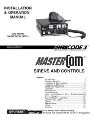
Unpacking & Pre-installationAfter unpacking the items, carefully inspect the contents for damage that may have occurred during transit. Ifany item is damaged, please contact the carrier immediately.To test the operation of the product before installation follow the directions given below:RDL2SF , RDL1SF, RDL1SB - Self-contained L.E.D. lighting units can be tested by inserting the cigaretteplug-in of the power cord into an appropriate +12 Vdc socket.If the vehicle has an electrical system This Product other than contains +12 Vdc, high contact intensity your <strong>LED</strong> local devices. representative To prevent or eye call damage, theElectronics Technical Assistance DO HOTLINE NOT stare at into (314)996-2800 light beam at for close instructions. range.WARNING! !<strong>Installation</strong> & Mounting!WARNING!This unit must be mounted within the interior passenger compartment of the vehicle only.It is not intended for use in exterior applications.All devices should be mounted in accordance with the manufacturer's instructions andsecurely fastened to vehicle elements of sufficient strength to withstand the forces appliedto the device. Driver and/or passenger air bags (SRS) will affect the way equipmentshould be mounted. This device should be mounted by permanent installation and withinthe zones specified by the vehicle manufacturer, if any. Any device mounted in thedeployment area of an air bag will damage or reduce the effectiveness of the air bag andmay damage or dislodge the device. Installer must be sure that this device, its mountinghardware and electrical supply wiring does not interfere with the air bag or the SRS wiringor sensors. Mounting the unit inside the vehicle by a method other than permanentinstallation is not recommended as unit may become dislodged during swerving, suddenbraking or collision. Failure to follow instructions can result in personal injury.Vehicle WindshieldThe Rear View Mirrow lights are designed to be mounted to the windshieldor rear window of your vehicle. The following instructions mustbe followed to insure that the unit is mounted correctly. Attach the (1)set of suction cups to (1) of the mounting bracket (see Fig. 1 for orientation)with the #10 self tapping screws, do not overtighten the screws.Next, fasten the bracket without suction cups with (2) #10-24 machinescrews, #10 lock washers and #10-24 nuts, but do not tighten the nutsat this time. Mount the bracket assemblies to the rear of the RVM unitwith the (4)¼-20 carriage bolts and kep nuts, make sure one boltcaptures the tether cord between the bracket and the case as illustratedin Fig. 1. After the bracket assembly is fastened to the unit,adjust the bracket without suction cups so that the unit will be level with the groundwhen mounted to the windshield. Be certain that the vehicle is on level ground beforeadjusting the bracket. Also try to keep the unit as close to the windshield aspossible.This can be adjusted by sliding the bracket assembly up or back on the unitbefore tightening it down. When the angle is set, tighten all screws and nuts. SeeFig. 1 for assembly illustration. Once the unit is mounted on the windshield, locate aplace to mount other end of the tether cord. Depending on where the unit is mounted,the tether cord can be attached anywhere on the dash or to the roof of the vehicle,as long as it is into sheet metal. Hold the free end of the tether cord in position andverify that the <strong>LED</strong> unit cannot reach the passenger or driver. Then, attach thetether cord to this section of sheet metal (not to plastic or rubber). Note: Whenremoving the unit from the windshield be sure to release the suction cups by liftingthe tabs on each suction cup. If the unit is pulled off the windshield, it could result instripping out the holes in the suction cups.FIGURE 13
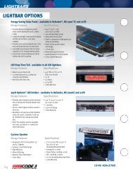
The RDM<strong>LED</strong> Rear <strong>Deck</strong> Mounting option allows the <strong>LED</strong> unit to be mounted to the rear deck of your vehicle.The following instructions must be followed to insure that the unit is mounted correctly:Attach the mounting hardware to the unit as shown in Fig. 2. Place the unit against the rear deck and makeadjustments with the hardware until the product is located in an area that does not obstruct the view or inflictinjury to either driver or passenger. Tighten loose hardware and mark the position of each mounting foot.Remove bracket assemblies from the unit. Using the marked positions, mount the brackets on the rear deckwith user supplied sheet metal screws or through-bolts. Mount the unit to the brackets using the included nutsand carriage bolts. Adjust the unit to provide the most effective signal.Caution: The unit must be mounted through the steel of the vehicle. Avoid mounting to plastic orother non-structural members.FIGURE 2MOUNTINGS14041Std. suction cupMounting kitOptional RVMMMSMirror Mount SystemOptional RDMRVMRear <strong>Deck</strong> Mtg. Bkt.4
Wiring InstructionsAll <strong>LED</strong>-X models are stand alone self-contained units ready for installation with no special wiringrequired. They are provided with a cigarette plug designed to be used with a +12VDC fused lighter socket.Alternately, the user can remove the plug and connect (through a properly sized fuse) to a user suppliedswitch. The ribbed wire is positive (+12VDC) and the smooth wire is negative.OperationThe <strong>LED</strong> series lightheads arrive completely assembled and ready for installation. They are designed tofunction at 10 - 16 VDC.To operate the <strong>LED</strong>-X unit, insert the cigarette plug provided into a +12VDC lighter socket androtate 1/4 turn to insure a good electrical connection.Flash PatternsLX1F-X 1 Head ModelSelecting and programming flash modes:This unit will provide up to ten different flash modes. Each of these modes can be selected by using the momentarybutton located on the end of the unit. Each flash mode can be selected by momentarily depressing thebutton until the unit stops flashing, and then releasing. As each flash mode is selected it is automaticallyprogrammed into the unit such that when power is removed it will always return to the selected mode the nexttime power is applied. If another mode is desired, just use the momentary button to step through each modeuntil the desired mode is found.Selecting and programming Cycle Flash mode:When shipped, the unit will be in “Cycle Flash mode”. This mode cycles through a variety of flash patternscontinuously providing an ever changing warning signal. If the unit is not in Cycle Flash, or you wish to return toCycle flash from another mode, then the momentary button should be depressed until the unit stops flashing,and held on for several seconds then released. This will program cycle flash into the unit.Flash PatternCycle FlashSteady-BurnFive FlashQuad FlashTriple FlashDouble FlashFast Double FlashNFPAQuad Pop FlashTriple Pop FlashDescriptionCycles through various patterns @ 70 fpmSteady-BurnFive Pulses per flash @ 70 fpmFour Pulses per flash @ 70 fpmThree Pulses per flash @ 70 fpmTwo Pulses per flash @ 70 fpmTwo Pulses per flash @ 85 fpmFour Pulses, 70% Duty Cycle @ 75 fpmFour Pulses per flash ( 3 equal, 1 extended) @ 70 fpmThree Pulses per flash ( 2 equal, 1 extended) @ 70 fpmLX1SB-X 1-Head ModelThis unit will provide one steady-burn operation mode. It can be used as a stationary warning light, it can alsobe flashed with an external relay-based flasher.5
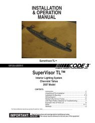
LX2F-XX: 2 Head ModelSelecting and programming flash modes:This unit will provide up to twenty one different flash modes. Each of these modes can be selected by using themomentary button located on the end of the unit. Each flash mode can be selected by momentarily depressingthe button until the unit stops flashing, and then releasing. As each flash mode is selected it is automaticallyprogrammed into the unit such that when power is removed it will always return to the selected mode the nexttime power is applied. If another mode is desired, just use the momentary button to step through each modeuntil the desired mode is found.Selecting and programming Cycle Flash mode:When shipped, the unit will be in “Cycle Flash mode”. This mode cycles through a variety of flash patternscontinuously providing an ever changing warning signal. If the unit is not in Cycle Flash, or you wish to return toCycle flash from another mode, then the momentary button should be depressed until the unit stops flashing,and held on for several seconds then released. This will program cycle flash into the unit.Flash Modes:Alternating Heads Simultaneous Heads Steady with FlashingCycle Flash Quad Flash Fast Double Flash w/SteadySingle Flash Triple Flash Quad Flash w/SteadyDouble FlashDouble FlashTriple Flash Single FlashQuad FlashPursuit FlashFive FlashFast Single FlashFast Double FlashFast Triple FlashFast Quad FlashQuad Pop FlashTriple Pop FlashDouble Pop FlashWig-Wag Flash Alt.Note: All modes flash at a rate of 70 fpm minimum. Fast modes flash at a rate of 100 fpm minimum.LX3F-XXX 3 Head ModelSelecting and programming flash modes:This unit will provide up to ten different flash modes. The unit will be in "Cycle Flash" mode as the standardpattern. The mode can be changed by shorting the 2-pin header, J1 as shown in Figure 3 on the next page.This will require disassembly of the unit in order to gain access to each of the individual control boards. Thetable in Figure 3 shows the available patterns and the order when stepping through patterns. As each flashmode is selected it is automatically programmed into the unit such that when power is removed it will alwaysreturn to the selected mode the next time power is applied.Selecting and programming Cycle Flash mode:When shipped, the unit will be in “Cycle Flash" mode. This mode cycles through a variety of flash patternscontinuously providing an ever changing warning signal. If the unit is not in "Cycle Flash", or you wish to returnto "Cycle Flash" from another mode, the module can be reset to "Cycle Flash" by shorting the header forgreater than 5 seconds and releasing.6
Flash PatternCycle FlashSteady-BurnFive FlashQuad FlashTriple FlashDouble FlashFast Double FlashNFPAQuad Pop FlashTriple Pop FlashDescriptionCycles through various patterns @ 70 fpmSteady-BurnFive Pulses per flash @ 70 fpmFour Pulses per flash @ 70 fpmThree Pulses per flash @ 70 fpmTwo Pulses per flash @ 70 fpmTwo Pulses per flash @ 85 fpmFour Pulses, 70% Duty Cycle @ 75 fpmFour Pulses per flash ( 3 equal, 1 extended) @ 70 fpmThree Pulses per flash ( 2 equal, 1 extended) @ 70 fpmMomentarily short and releaseto change patternsJ1PCBFlash Pattern Header for <strong>LED</strong>XFIGURE 3Options & Specifications(Currents are calculated at 12.8 volts)MODEL H L D WEIGHT OPERATING CURRENT FLASHVOLTAGE DRAW RATELX3F-XXX - 3 Head 1.75" 13.8" 2.75" 2.0 lbs 10-16Vdc .6A avg 70 fpmL.E.D. warning systemminLX2F-XX - 2 Head 1.75" 9.3" 2.75" 1.3 lbs 10-16Vdc .6A avg 70 fpmL.E.D. warning systemminLX1F-X - 1 Head 1.75" 4.8" 2.75" 1 lbs 10-16Vdc Blue-.4A avg 70 fpmL.E.D. warning system Red/Amber- min.25A avgLX1SB-X - 1Head 1.75" 4.8" 2.75" 1 lbs 10-16Vdc Blue-.8A avgL.E.D. warning system Red/Amber- NA.5A avg7
MaintenanceThe product is designed for minimal maintenance and trouble free service. Periodic inspection of the productwill ensure trouble free operation. However, occasional cleaning of the lenses is required to sustain maximumlight output. Use plain water and a soft cloth, or <strong>Code</strong> 3 lens polish and a very soft paper towel or facial tissue.Note: Plastic scratches easily, be careful when cleaning the optic filters.Should problems arise during installation or during the life of the product, refer to the guide below for informationon troubleshooting. Additional information may be obtained from the factory technical HOTLINE at(314) 996-2800.Note: Should this Product be diagnosed as containing a diffective light-head module, contact CODE3 andarrange to ship entire unit back to factory for service.TROUBLESHOOTINGPROBABLE CAUSEREMEDYProduct does not activate a. No power to unit a. Check wiring for looseconnection.b. Power input wires reversed b. Check power connectionsc. Damaged or shorted cabling c. Check cables for damage8
Parts ListRef No. Description Part No. LX1F-X/LX1SB-XLX2F-XX LX3F-XXX1 Switch T05742 1 1 -2 Switch Harness T05763 1 1 -3 Clear Lens T05735 - 1 -T05734 1 - -T89943 - - 14 Extrusion T05724 - 1 -T05737T899421----15 End Cap T02650 2 2 26 RVM Suction Cup Mtg. Kit S14041 1 1 1Not shown Optional RVMMMS Mfg. Kit RVMMMS 1 1 -Not shown #6x1/2" sheetmetal screw T02797 8 8 8Not shown Adhesive Pad T01665 1 1 1Not shown Hole plug T00337 1 1 1Not shown Optional RDMRVM Mtg. Kit RDMRVM 1 1 1Not shown Cig. Lighter Cable Ass'y T03042 1 1 1643125Figure 49
2001-03 Ford Crown Vic and 2001-02 Dodge Intrepid<strong>Installation</strong> and Mounting1) Remove sun visor clips.2) Slide bracket between the headliner and the roof of car.3) Horizontal slots on up-turned flange of bracket will align with existing holes in roof.4) Slots on flat part of bracket will align with the hole for the sun visor clips.5) Run T01072 5/16" - 18 sheet metal screws through slot in up turned flange into holesin roof.6) Re-attach sun visor clips through slots on the flat part of the bracket.7) Attach <strong>LED</strong> X unit to bracket.2001-02 Chevy Impala<strong>Installation</strong> and Mounting1) Remove sun visor clips.2) Slide bracket between the headliner and the roof of car.3) Slots on flat part of bracket will align with the hole for the sun visor clips.4) Drill 1/8" holes at 3/16" hole locations of bracket into roof support.5) Run T05336 #8 sheet metal screws through holes in up turned flanges intoholes drilled in roof support.6) Re-attach sun visor clips through slots on the flat part of the bracket.7) Attach <strong>LED</strong> X unit to bracket.10
2007 Chevrolet Tahoe<strong>Installation</strong> and Mounting1) Remove sun visor clips.2) Remove rear view mirror from windshield mount3) Place bracket over top of the headliner of vehicle.4) Rectangular slots on bracket will align with the hole for the sun visor clips.5) Re-attach sun visor clips through slots on the flat part of the bracket.6) Re-attach rear view mirror to windshield mount.7) Attach <strong>LED</strong> X unit to bracket.2007 Dodge Charger<strong>Installation</strong> and Mounting1) Remove sun visor clips.2) Remove rear view mirror from windshield mount.3) Slide bracket between the headliner and the roof of car.4) X-slots on bracket will align with the holes for the sun visor clips.5) Re-attach sun visor clips through slots on the flat part of the bracket.6) Re-attach rear view mirror to windshield mount.7) Attach <strong>LED</strong> X unit to bracket.11
WARRANTY<strong>Code</strong> 3, Inc. L.E.D. emergency devices are tested and found to be operational at the time ofmanufacture. Provided they are installed and operated in accordance with manufacturer's recommendations,<strong>Code</strong> 3, Inc. guarantees all parts and components to a period of 5 years (unless otherwise expressed) fromthe date of purchase or delivery, whichever is later. Units demonstrated to be defective within the warrantyperiod will be repaired or replaced at the factory service center at no cost.Use of inappropriate or inadequate wiring or circuit protection causes this warranty to become void.Failure or destruction of the product resulting from abuse or unusual use and/or accidents is not coveredby this warranty. <strong>Code</strong> 3, Inc. shall in no way be liable for other damages including consequential, indirector special damages whether loss is due to negligence or breach of warranty.CODE 3, INC. MAKES NO OTHER EXPRESS OR IMPLIED WARRANTY INCLUDING, WITH-OUT LIMITATION, WARRANTIES OF FITNESS OR MERCHANTABILITY, WITH RESPECT TOTHIS PRODUCT.PRODUCT RETURNSIf a product must be returned for repair or replacement*, please contact our factory to obtain a ReturnGoods Authorization Number (RGA number) before you ship the product to <strong>Code</strong> 3, Inc. Write the RGAnumber clearly on the package near the mailing label. Be sure you use sufficient packing materials to avoiddamage to the product being returned while in transit.*<strong>Code</strong> 3, Inc. reserves the right to repair or replace at its discretion. <strong>Code</strong> 3, Inc. assumes no responsibility or liability for expenses incurred for the removal and /or reinstallation of products requiring service and/or repair.; nor for the packaging, handling, and shipping: nor for the handling of products returned to sender after theservice has been rendered.NEED HELP? Call our Technical Assistance Hotline - (314) 996-2800<strong>Code</strong> 3 , Inc.10986 N. Warson RoadSt. Louis, Missouri 63114-2029—USAwww.code3pse.comRVM and <strong>LED</strong> X are trademarks and <strong>Code</strong> 3 is a registered trademark of <strong>Code</strong> 3, Inc. a subsidiary of <strong>Public</strong> <strong>Safety</strong> Equipment, Inc.12Revision 6, 2/2007 - Instruction Book Part No. T05767©2002-7 <strong>Code</strong> 3, Inc. Printed in USA