Create successful ePaper yourself
Turn your PDF publications into a flip-book with our unique Google optimized e-Paper software.
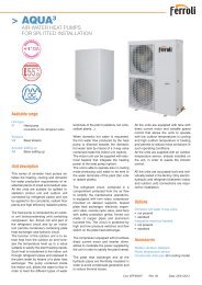
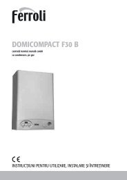
<strong>RLA</strong> <strong>HE</strong>CLASSEAIR-WATER CHILLERS AND <strong>HE</strong>AT PUMPSFOR OUTDOOR INSTALLATIONEUROVENT EFFICIENCYENERGYCLASSGARANZIAAvailable rangeanniUnit typeIR ChillerIP Heat pump(reversible on the refrigerant side)BR Chiller BrineBP Heat pump Brine(reversible on the refrigerant side)VersionVB Base versionVD Desuperheater versionVR Total recovery versionAcoustic setting upAB Base setting upAS Low noise setting upAX eXtra low noise setting upSource temperature levelM Medium temperature levelA High temperature levelUnit descriptionThis series of air-water chillers and heatpumps satisfies the cooling and heatingrequirements of residential plants of medium-largesize.All the units are suitable for outdoor installationand can be applied to fan coilplants, radiant floor plants and high efficiencyradiators plants.The refrigerant circuit, contained in acompartment protected from the air flowto simplify the maintenance operations,is equipped with scroll compressorsmounted on damper supports, brazedplate heat exchanger, electronic expansionvalve, reverse cycle valve, dehydratorfilter, axial fans with safety protectiongrilles, finned coil made of copper pipesand aluminium louvered fins with subcoolingsection. The circuit is protected by asafety gas valve, high and low pressureswitches and differential pressure switchon the plate heat exchanger. The plateheat exchanger and all the hydraulic pipesare thermally insulated in order to avoidcondensate generation and to reducethermal losses.All the units can be equipped with variablespeed fans control that allows the units tooperate with low outdoor temperatures incooling and high outdoor temperature inheating and permits to reduce noise emissionsin such operating conditions.The low noise acoustic setting up (AS) isobtained, starting from the base setting up(AB), reducing the rotational speed of thefans and mounting sound jackets on thecompressors and the technical compartmentis clad with soundproofing materialof suitable thickness.The eXtra low noise acoustic setting up(AX) is obtained, starting from the lownoise setting up (AS), further reducing therotational speed of the fans and using finnedcoil with bigger surface.All the units are supplied with a managementand control electrical panel containinggeneral switch, phase presence andcorrect sequence controller, microprocessorcontroller with display and all the otherelectrical components with IP54 minimumprotection degree.All the units are accurately built and individuallytested in the factory. Only electricand hydraulic connections are required forinstallation.CAOptionsStoring and pumping module available inthe configurations :• storage tank arranged as buffer on theflow or as primary-secondary buffer• 1 or 2 pumps• standard or high head pumpRefrigerant circuit pressures visualization• high and low pressure gauges• high and low pressure transducersHigh temperature thermostatCompressor starting• standard (contactors)• soft starterFans control• on-off control• modulating control (condensation / evaporationcontrol)Compressor power factor correctionElectrical load protection• fuses• thermal magnetic circuit breakersCoil condensate trayAccessoriesARubber vibration dampersSpring vibration dampersCoil protection grillesTank antifreeze electrical heaterRemote controlModbus serial interface on RS485Programmer clockPhase sequence and voltage controllerWater flow switchVictaulic hydraulic fittingsCod. BTP00504 Rev. 00 Data: 26/04/2011
<strong>RLA</strong> <strong>HE</strong> AIR-WATER CHILLERS AND <strong>HE</strong>AT PUMPS FOR OUTDOOR INSTALLATIONNOMINAL performances - Standard plantsIR Base setting up (AB) 160.4 180.4 200.4 230.4 260.4 290.4 330.4 375.4Cooling capacity 168 191 214 241 271 309 348 396 kWPower input 54,1 61,3 68,0 76,7 86,8 98,2 109 127 kWEER 3,11 3,12 3,15 3,14 3,12 3,15 3,19 3,12 -ESEER 4,47 4,49 4,53 4,52 4,50 4,53 4,60 4,49 -Pressure drops 43 44 47 48 45 43 44 38 kPaIR Low noise setting up (AS) 160.4 180.4 200.4 230.4 260.4 290.4 330.4 375.4Cooling capacity 160 181 203 229 257 294 331 376 kWPower input 55,3 62,9 70,1 79,4 88,9 101 112 130 kWEER 2,89 2,88 2,90 2,88 2,89 2,91 2,96 2,89 -ESEER 4,34 4,32 4,34 4,33 4,34 4,37 4,43 4,34 -Pressure drops 39 40 42 43 40 38 40 34 kPaIR eXtra low noise setting up (AX) 160.4 180.4 200.4 230.4 260.4 290.4 330.4 375.4Cooling capacity 158 180 201 227 255 290 327 372 kWPower input 55,9 63,8 71,2 80,8 90,1 103 114 132 kWEER 2,83 2,82 2,82 2,81 2,83 2,82 2,87 2,82 -ESEER 4,52 4,51 4,52 4,50 4,53 4,50 4,59 4,51 -Pressure drops 38 40 41 42 40 38 39 33 kPaIP Base acoustic setting up (AB) 160.4 180.4 200.4 230.4 260.4 290.4 330.4 375.4Cooling capacity 165 187 209 236 263 302 341 389 kWPower input 52,9 60,1 66,6 75,4 84,3 96,3 107 125 kWEER 3,12 3,11 3,14 3,13 3,12 3,14 3,19 3,11 -ESEER 4,49 4,48 4,52 4,51 4,49 4,52 4,59 4,48 -Pressure drops 42 43 44 46 42 41 42 36 kPaHeating capacity 174 198 221 251 280 320 361 412 kWPower input 54,1 61,5 68,4 77,2 87,2 99,1 111 128 kWCOP 3,22 3,22 3,23 3,25 3,21 3,23 3,25 3,22 -Pressure drops 47 48 50 52 48 46 48 41 kPaIP Low noise setting up (AS) 160.4 180.4 200.4 230.4 260.4 290.4 330.4 375.4Cooling capacity 157 178 199 224 250 287 324 370 kWPower input 53,9 61,6 68,6 78,0 86,2 99,0 110 128 kWEER 2,91 2,89 2,90 2,87 2,90 2,90 2,95 2,89 -ESEER 4,37 4,33 4,35 4,31 4,35 4,35 4,42 4,34 -Pressure drops 38 39 40 41 38 37 38 33 kPaHeating capacity 169 192 214 243 272 310 350 400 kWPower input 51,4 58,8 65,6 74,4 83,2 95,0 107 122 kWCOP 3,29 3,27 3,26 3,27 3,27 3,26 3,27 3,28 -Pressure drops 44 45 46 49 45 43 45 38 kPaIP eXtra low noise setting up (AX) 160.4 180.4 200.4 230.4 260.4 290.4 330.4 375.4Cooling capacity 155 176 196 222 247 284 321 366 kWPower input 54,6 62,5 69,7 79,3 87,3 101 112 130 kWEER 2,84 2,82 2,81 2,80 2,83 2,81 2,87 2,82 -ESEER 4,54 4,51 4,50 4,48 4,53 4,50 4,59 4,50 -Pressure drops 37 38 39 41 37 36 37 32 kPaHeating capacity 167 190 212 241 269 307 347 396 kWPower input 50,2 57,5 64,3 73,0 81,3 93,0 105 120 kWCOP 3,33 3,30 3,30 3,30 3,31 3,30 3,30 3,30 -Pressure drops 43 44 45 48 44 42 44 38 kPaA35W7A35W7A35W7A35W7A7W45A35W7A7W45A35W7A7W45A35W7 = source : air in 35°C d.b. / plant : water in 12°C out 7°CA35W18 = source : air in 35°C d.b. / plant : water in 23°C out 18°CA7W45 = source : air in 7°C d.b. 6°C w.b. / plant : water in 40°C out 45°CA7W35 = source : air in 7°C d.b. 6°C w.b. / plant : water in 30°C out 35°CTECHNICAL DATA 160.4 180.4 200.4 230.4 260.4 290.4 330.4 375.4Power supply 400 - 3 - 50Compressor type scroll -N° compressors / N° refrigerant circuits 4 / 2 n°Plant side heat exchanger type stainless steel brazed plates -Source side heat exchanger type finned coil -Fans type axial -N° fans 4 6 8 n°Tank volume 325 710 lHydraulic fittings 3” VICTAULIC 4” VICTAULIC -V-ph-Hz
<strong>RLA</strong> <strong>HE</strong> AIR-WATER CHILLERS AND <strong>HE</strong>AT PUMPS FOR OUTDOOR INSTALLATIONNOMINAL performances - Standard plantsIR Base setting up (AB) 160.4 180.4 200.4 230.4 260.4 290.4 330.4 375.4Cooling capacity 167 190 212 239 269 307 346 394 kWPower input 55,3 62,7 69,6 78,5 88,7 100 111 129 kWEER 3,02 3,03 3,05 3,04 3,03 3,07 3,12 3,05 -Water flow rate 8,03 9,13 10,22 11,5 12,9 14,8 16,6 18,9 l/sPressure drops 43 44 47 48 45 43 44 38 kPaIP Base setting up (AB) 160.4 180.4 200.4 230.4 260.4 290.4 330.4 375.4Cooling capacity 164 186 208 234 261 300 339 387 kWPower input 54,0 61,4 68,1 77,1 86,1 98,3 109 127 kWEER 3,04 3,03 3,05 3,04 3,03 3,05 3,11 3,05 -Water flow rate 7,88 8,93 9,99 11,3 12,6 14,4 16,3 18,6 l/sPressure drops 42 43 44 46 42 41 42 36 kPaHeating capacity 175 200 223 253 282 322 364 415 kWPower input 55,4 63,0 70,1 79,3 89,3 101 114 131 kWCOP 3,16 3,17 3,18 3,19 3,16 3,19 3,19 3,17 -Water flow rate 8,31 9,46 10,6 12,0 13,4 15,3 17,2 19,7 l/sPressure drops 47 48 50 52 48 46 48 41 kPaA35W7A35W7A7W45Data declared according to EN 14511. The values are referred to units without options and accessories.NOMINAL performances - Radiant plantsIR Base setting up (AB) 160.4 180.4 200.4 230.4 260.4 290.4 330.4 375.4Cooling capacity 215 245 275 309 348 397 447 510 kWPower input 60,4 68,5 76,4 86,3 97,1 110 122 141 kWEER 3,56 3,58 3,60 3,58 3,58 3,61 3,66 3,62 -Water flow rate 10,4 11,8 13,3 15,0 16,8 19,2 21,6 24,6 l/sPressure drops 73 74 79 81 75 72 75 64 kPaIP Base setting up (AB) 160.4 180.4 200.4 230.4 260.4 290.4 330.4 375.4Cooling capacity 213 240 269 303 338 389 438 501 kWPower input 59,1 67,1 74,7 84,7 94,0 107 119 138 kWEER 3,60 3,58 3,60 3,58 3,60 3,64 3,68 3,63 -Water flow rate 10,3 11,6 13,0 14,7 16,3 18,8 21,2 24,2 l/sPressure drops 71 72 75 78 71 69 72 62 kPaHeating capacity 186 212 236 269 299 342 386 440 kWPower input 46,2 52,4 58,3 65,7 74,4 84,3 94,2 108 kWCOP 4,03 4,05 4,05 4,09 4,02 4,06 4,10 4,07 -Water flow rate 8,81 10,00 11,2 12,7 14,2 16,2 18,3 20,9 l/sPressure drops 52 53 56 58 54 51 54 46 kPaA35W18A35W18A7W35Data declared according to EN 14511. The values are referred to units without options and accessories.Acoustic performancesBase setting up (AB) 160.4 180.4 200.4 230.4 260.4 290.4 330.4 375.4Sound power level 91 92 92 92 93 94 94 95 dB(A)Sound pressure level at 1 metre 72 73 73 73 74 75 74 75 dB(A)Sound pressure level at 5 metres 64 65 65 65 66 67 67 68 dB(A)Sound pressure level at 10 metres 59 60 60 60 61 62 62 63 dB(A)Low noise setting up (AS) 160.4 180.4 200.4 230.4 260.4 290.4 330.4 375.4Sound power level 85 86 86 86 87 88 88 89 dB(A)Sound pressure level at 1 metre 66 67 67 67 68 69 68 69 dB(A)Sound pressure level at 5 metres 58 59 59 59 60 61 61 62 dB(A)Sound pressure level at 10 metres 53 54 54 54 55 56 56 57 dB(A)eXtra low noise setting up (AX) 160.4 180.4 200.4 230.4 260.4 290.4 330.4 375.4Sound power level 82 83 83 83 84 85 85 86 dB(A)Sound pressure level at 1 metre 63 64 64 64 65 66 65 66 dB(A)Sound pressure level at 5 metres 55 56 56 56 57 58 58 59 dB(A)Sound pressure level at 10 metres 50 51 51 51 52 53 53 54 dB(A)The acoustic performances are referred to units operating in cooling mode at nominal conditions A35W7.Unit placed in free field on reflecting surface (directional factor equal to 2).The sound power level is measured according to ISO 3744 standard.The sound pressure level is calculated according to ISO 3744 and is referred to a distance of 1/5/10 metres from the external surface of the unit.CoolingHeatingOPERATING LIMITS Unit type min max min maxOutdoor air inlet temperature IR, BR, IP, BP -10* 55** -15 40* (°C)Water outlet temperature IR, IP 5 25 30 55 (°C)Water outlet temperature BR, BP -12 25 30 55 (°C)Water outlet temperature (VD) IR, BR, IP, BP 30 70 30 70 (°C)Water outlet temperature (VR) IR, BR 30 55 - - (°C)* with fans modulating control option (condensation / evaporation control)** with ATC outdoor high temperature protection fuction
<strong>RLA</strong> <strong>HE</strong> AIR-WATER CHILLERS AND <strong>HE</strong>AT PUMPS FOR OUTDOOR INSTALLATIONVD and VR versionsThese units allow to recover the heating power, otherwise wasted on air, through an additional heat exchanger.The Desuperheater Version (VD) allow the hot water productionat temperatures between 30 and 70°C through the partial heatrecovery of the condensation heat.DIMENSIONS - MINIMUM OPERATING AREA - WEIGHTThe Total Recovery Version (VR) allows the cold water productionand, at the same time, the hot water production at temperaturesbetween 30 and 55°C through the total recovery of thecondensation heat.Desupeheater Version (VD)IR Base setting up (AB) 160.4 180.4 200.4 230.4 260.4 290.4 330.4 375.4Cooling capacity 174 198 223 251 282 321 362 412 kWTotal power input 52,7 59,7 66,2 74,6 84,6 95,6 106 123 kWEER 3,30 3,32 3,37 3,36 3,33 3,36 3,42 3,35 -Water flow rate 8,31 9,46 10,7 12,0 13,5 15,3 17,3 19,7 l/sWater pressure drop 47 48 51 52 48 46 48 41 kPaHeating recovery capacity 50,5 57,4 64,7 72,8 81,8 93,1 105 119 kWWater flow rate recovery 2,41 2,74 3,09 3,48 3,91 4,45 5,02 5,71 l/sWater pressure drop recovery 6 8 10 12 15 15 18 23 kPaIP Base setting up (AB) 160.4 180.4 200.4 230.4 260.4 290.4 330.4 375.4A35W7 - W45Cooling capacity 172 194 218 245 273 314 354 405 kWTotal power input 51,5 58,5 64,8 73,4 82,1 93,7 104 121 kWEER 3,34 3,32 3,36 3,34 3,33 3,35 3,40 3,35 -Water flow rate 8,22 9,27 10,4 11,7 13,0 15,0 16,9 19,4 l/sWater pressure drop 46 46 48 50 45 44 46 40 kPaHeating recovery capacity 49,9 56,3 63,2 71,1 79,2 91,1 103 117 kWWater flow rate recovery 2,38 2,69 3,02 3,39 3,78 4,35 4,90 5,61 l/sWater pressure drop recovery 6 8 10 12 14 14 17 23 kPaTotal Recovery Version (VR)IR Base setting up (AB) 160.4 180.4 200.4 230.4 260.4 290.4 330.4 375.4A35W7 - W45A35W7 - W45Cooling capacity 174 198 223 251 282 321 362 412 kWTotal power input 45,0 51,9 58,4 66,7 73,0 83,9 94,1 108 kWEER 3,87 3,82 3,81 3,76 3,87 3,82 3,85 3,82 -EER with recovery 8,69 8,60 8,58 8,47 8,69 8,60 8,66 8,59 -Water flow rate 8,33 9,48 10,6 12,0 13,5 15,3 17,3 19,7 l/sWater pressure drop 47 48 50 52 48 46 48 41 kPaHeating recovery capacity 217 248 278 314 352 401 452 515 kWWater flow rate recovery 10,4 11,8 13,3 15,0 16,8 19,2 21,6 24,6 l/sWater pressure drop recovery 36 38 38 40 40 42 43 45 kPaA35W7 - W45 = source : air in 35°C d.b. / plant : water in 12°C out 7°C / Recovery : water in 40°C out 45°CCONTROL SYSTEMThe units are equipped with a controller designed to ensure energy saving and unit efficiency. Available functions :- ATC outdoor high temperature protection function- Dynamic defrost- Sound management- Climatic control in heating and in cooling mode- Double set point function- Demand limit- Integrative heating- Remote stand by- Remote cooling-heating160.4 180.4 200.4 230.4 260.4 290.4 330.4 375.4L 3164 3164 3164 3164 3164 4097 4097 4097 mmOperating maximum weight 2441 2633 2829 3005 3069 3690 3790 3907 kg