You also want an ePaper? Increase the reach of your titles
YUMPU automatically turns print PDFs into web optimized ePapers that Google loves.
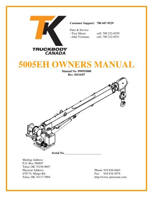
Customer Support: 780 447-9529Parts & Service- Troy Mazar cell: 780 232-6559- John Yeomans cell: 780 232-6551<strong>5005EH</strong> <strong>OWNERS</strong> <strong>MANUAL</strong>Manual No. 999955000Rev. 04/16/07Serial No. ________________________Mailing Address:P.O. Box 580697Tulsa, OK 74158-0697Physical Address: Phone: 918 836-04634707 N. Mingo Rd. Fax: 918 834-5979Tulsa, OK 74117-5904http://www.autocrane.com
Auto Crane Warranty RegistrationFax TransmissionTo:Warranty DepartmentFax:(918) 834-5979From:Date:Re:Product RegistrationPages:End User Information:(Required for Warranty Activation)Name:Phone:Address:City: State: Zip:Contact:E-mail Address:Distributor Information:(Required for Warranty Activation)Name:Address:City: State: Zip:Contact:E-mail Address:Product Information:Model No.:Date Product Delivered:VIN #(Required for Warranty Activation)Serial No.:Date Processed:** For Auto Crane use onlyONE REGISTRATION FORM PER UNIT (CRANE OR BODY)Registration form must be mailed or faxed within 15 days of customer installation.Mail to:Warranty DepartmentAuto Crane CompanyP.O. Box 581510Tulsa, OK 74158-0697Warranty Registration Rev. 072403
<strong>5005EH</strong>OWNER’S <strong>MANUAL</strong> REVISION RECORDRevisionDateSection(s)OrPage(s)Description of Change09/02/03 Last Page New 2-year warranty policy to replace 1-year warranty policy02/22/06 All Pages New Design – Added FM03/20/06 7-4.1 thru 7-5.1 Added Relay Pnl & updated artwork of hardwired pendant05/05/06 6,7,& 11 Updated pedestal assy, voltage switching unit, & load chart.04/16/07 6-1.0, 6-5.0, 7-1.0& 7-5.0Updated general assy, pedestal, schematic & relay panelNotes:1. The information contained in this manual is in effect at the time of this printing. It doesnot cover all instructions, configurations, accessories, etc. If you require additionalinformation, please contact Auto Crane Company at (918) 836-0463.2. Auto Crane Company reserves the right to update this material without notice orobligation.
WARNINGSWARNING! Federal law (49 cfr part 571) requires that the Final Stage Manufacturer of a vehiclecertify that the vehicle complies with all applicable federal regulations. Any modifications performedon the vehicle prior to the final state are also considered intermediate stage manufacturing and mustbe certified as to compliance. The installer of this crane and body is considered one of themanufacturers of the vehicle. As such a manufacturer, the installer is responsible for compliancewith all applicable federal and state regulations, and is required to certify that the vehicle is incompliance.WARNING! It is the further responsibility of the installer to comply with the OSHA Truck CraneStability Requirements as specified by 29 CFR part 1910.180 (C) (1).WARNING! NEVER OPERATE THE CRANE NEAR ELECTRICAL POWER LINES!Death or serious injury will result from boom, line, or load contacting electric lines. Do not use cranewithin 10 feet (3.05m) of electric power lines carrying up to 50,000 volts. One-foot additionalclearance is required for every additional 30,000 volts or less. SEE DANGER DECAL (P/N 040529)in this Owner's Manual.WARNING! NEVER.........................................♦ EXCEED load chart capacities (centerline of rotation to hoist hook).♦ Un-reel last 5 wraps of cable from drum!♦ Wrap cable around load!♦ Attempt to lift or drag a load from the side! The boom can fail far below its rated capacity.♦ Weld, modify, or use unauthorized components on any Auto Crane unit! This will void anywarranty or liability. Also failure of the crane may result.♦ Place a chain link on the tip of the hook and try to lift a load!♦ Use a sling bar or anything larger than the hook throat that could prevent the hook latch fromclosing, thus negating the safety feature!♦ Hold on any pendant Select Switch that will cause unsafe operating conditions!WARNING! In using a hook with latch, ALWAYS make sure that the hook throat is closed beforelifting a load! Proper attention and common sense applied to the use of the hoist hook and variousslings will prevent possible damage to material being hoisted and may prevent injury to personnel.WARNING! Failure to correctly plumb and wire crane can cause inadvertent operation and damageto crane and/or personnel!WARNING! Auto Crane Company remote controlled cranes are not designed or intended for use forany applications involving the lifting or moving of personnel.WARNING! ALWAYS operate the crane in compliance with the load capacity chart. DO NOT USEthe overload shutdown device to determine maximum rated loads, if the crane is equipped with thistype of device.READ THIS PAGE8/15/05
<strong>5005EH</strong>TABLE OF CONTENTSGENERAL ASSEMBLY, FM, (W/SLIP RING & W/O SLIP RING) 9-1.0FM CONTROL USE & CARE 10-1.0TRANSMITTER ASSEMBLY, FM 10-2.0DIAGNOSTICS, FM 10-4.0TROUBLESHOOTING, FM 10-6.0ID CODE PROGRAMMING 10-9.0LOAD CHART 11-1.0WARRANTYLAST PAGE5/5/06
<strong>5005EH</strong>INTRODUCTIONAuto Crane products are designed toprovide many years of safe, trouble-free,dependable service when properly used andmaintained.To assist you in obtaining the best servicefrom your crane and to avoid untimely craneand/or vehicle failure, this manual providesthe following operating and serviceinstructions. It is specifically recommendedthat all operating and service personnelconsider this manual as mandatory materialfor reading and study before operating orservicing Auto Crane products. It is highlyrecommended that crane owners, equipmentmanagers, and supervisors also read thismanual.Auto Crane has incorporated several safetyfeatures in the <strong>5005EH</strong> crane for yourprotection.For your convenience the overalldimensions of the <strong>5005EH</strong> crane areincluded on the General DimensionDrawing. Rotation and turning radius arealso listed on that drawing.Remember, the crane adds weight to thevehicle. Adding weight may change thedriving and riding characteristics of thevehicle unless the appropriate overloadspring(s) are installed on the truck. Thepayload of the vehicle is reduced by theweight of the crane. The operator shouldexercise care when loading the vehicle.Distributing the payload on the vehicleevenly will greatly improve the driving andriding characteristics of the vehicle.Auto Crane Company issues a limitedwarranty certificate with each unit sold.See last page for warranty.The <strong>5005EH</strong> cranes are attached to yourtruck electrical system through the VoltageSwitching Unit provided. The <strong>5005EH</strong> isanother highly efficient Auto Crane product.The use of a maintenance-free battery is notrecommended on any Auto Crane product.The recommended alternator and batterythat will give the longest life with the mostuseful duty cycle is a 75-amp1-1.0alternator with a 500 cold cranking ampbattery. These specifications should beconsidered minimum.It has always been Auto Crane Companypolicy to handle all warranty claims we receiveas promptly as possible. If a warranty claiminvolves discrepant material or workmanship,Auto Crane will take immediate correctiveaction. It is understandable that Auto CraneCompany cannot assume responsibility ofliability when it is obvious that our productshave been abused, misused, overloaded orotherwise damaged by inexperienced personstrying to operate the equipment withoutreading the manual.Auto Crane will not assume responsibilityor liability for any modifications orchanges made to unit, or installation ofcomponent parts without authorization.Auto Crane maintains a strong distributornetwork and a knowledgeable CustomerService Department. In most cases, anequipment problem is solved via phoneconversation with our customer servicedepartment. The customer service departmentalso has the ability to bring a local distributor,a regional sales manager, or a factoryserviceman into the solution of an equipmentproblem.If, through no fault of Auto Crane Company, itis necessary to send an experienced factoryserviceman on a field service call the ratesstated in the Auto Crane Distributor's Flat RateManual will apply.Auto Crane Company's extensive Researchand Development Program allow ourcustomers to use the best equipment on themarket. Our Engineering Staff and ourknowledgeable sales people are alwaysavailable to our customers in solving craneand winch-type application problems. When indoubt, call the Auto Crane factory.Note: This manual should remain with thecrane at all times.12/05/05
<strong>5005EH</strong>INTRODUCTIONDISTRIBUTOR ASSISTANCE:Should you require any assistance not givenin this manual, we recommend that youconsult your nearest Auto Crane Distributor.Our distributors sell authorized parts andhave service departments that can solvealmost any needed repair. This manualdoes not cover all maintenance, operating,or repair instructions pertinent to all possiblesituations. If you require additionalinformation, please contact the AutoCrane Company at the followingtelephone number: (918) 836-0463. Theinformation contained in the manual is ineffect at the time of this printing. Auto CraneCompany reserves the right to update thismaterial without notice or obligation.1-2.012/05/05
<strong>5005EH</strong>GENERAL SPECIFICATIONSDIMENSIONSWidth: 21.63 in (0.55 m)Height: 35.75 in (0.91 m)Length: 13 ft 1 in (3.99 m)[boom(s) stored]Weight:1,455 lbs (758 kg)CAPACITY25,000 ft-lbs (3.46 ton-m)[ft-lbs = horizontal distance from centerlineof rotation to free hanging weight (feet) xamount of weight (pounds)]LIFTING CAPACITIESft lbs ft lbs3 5,000 12 2,0834 5,000 13 1,9235 5,000 14 1,7866 5,000 15 1,6677 3,571 16 1,5628 3,125 17 1,4719 2,777 18 1,38910 2,500 19 1,31611 2,273 20 1,250REACHSecond boom will reach from 10 feet 4inches to 16 feet 4 inches.Third boom will reach from 16 feet 4inches to 20 feet 4 inches.CABLE80 ft (24.38 m) of 5/16 in (7.9 mm)diameter aircraft quality cable. This cablehas a single line breaking strength of9,800 lbs (4,444 kg).CHASSIS REQUIREMENTS14,500 lbs (6,577 kg) GVWR minimum360,000 in-lbs RBMELECTRICAL SYSTEMREQUIREMENTSVoltage:Alternator:Battery:24 VDC75 amp (minimum)130 minute reservecapacity (minimum)Maintenance typeROTATION370º Rotation With Electrical StopContinuous Rotation With Slip Ring1-3.012/05/05
--- IMPORTANT ---SAFETY TIPS AND PRECAUTIONS1. No unqualified or unauthorized person shall beallowed to operate the crane.2. WARNING: Never weld, modify, or useunauthorized components / parts on any AutoCrane unit. This will void any warranty orliability. Also, failure of the crane may result.3. Make certain the vehicle meets minimumchassis requirements. (These requirements donot guarantee unit stability.)4. Make certain the crane is installed per factoryspecifications. Contact your local distributor orthe Auto Crane factory if any questions arise.5. Visual inspections and tests should beconducted at the beginning of each shift eachday to insure that the crane and all its operatingsystems are in good condition and working orderbefore it is used.6. Inspect hydraulic hoses frequently for signs ofdeterioration, and replace them as required.7. If a hydraulic break occurs, leave the area of thebreak and do not attempt to stop the break byhand as the hydraulic oil may be hot and underhigh pressure which can cause serious injury.Shut the system down as soon as possible.8. Check the hook at least every thirty days fordistortions or cracks and replace it as required.9. Oil gears as required.10. Stop all operations when cleaning, adjusting orlubricating the machine.11. Keep dirt and grit out of moving parts by keepingcrane clean. Make sure machine is free ofexcess oil, grease, mud and rubbish, thusreducing accidents and fire hazards.12. When a new cable is installed, operate first witha light load to let the cable adjust itself.13. Locate the vehicle at the work site for the beststability possible.14. Keep the vehicle in a level position while loadingor unloading.15. Observe operating area for obstructions and/orpower lines that might be a hazard.16. WARNING: NEVER OPERATE THE CRANENEAR ELECTRICAL POWER LINES. AutoCrane Company recommends that the cranenever be any closer to a power line (includingtelephone lines) than 10 feet at any point.17. Allow the vehicle engine to warm up beforeoperating crane.18. Know the weight of your rigging and load toavoid overloading the crane.19. Deduct the weight of the load handlingequipment from the load rating to determine howmuch weight can be lifted.20. All load ratings are based on crane capacity,NOT the vehicle stability. Remember in lifting aheavy load, the weight can create enoughtipping moment to overturn the vehicle21. Always comply with load chart capacities,(centerline of rotation to hook).22. Secure all loads before lifting.23. Always set the emergency brake beforebeginning operation.24. Keep objects and personnel clear of crane pathduring operation.25. Operate control levers slowly and smoothly inorder to meter oil flow for safe operation.26. Always extend the outriggers from vehicle to theground before crane operation. Insure that theyare firmly positioned on solid footings. Standclear of outriggers while they are beingextended.27. If any outrigger, when extended, rests on a curbor other object that prevents it from extending toits maximum distance, shorten bearing orfulcrum point and reduce the maximum loadaccordingly.28. When an outrigger will not reach the ground dueto holes or grades, it shall be blocked up toprovide level and firm support for the truck.29. When working in soft earth, use wide padsunder outrigger feet to prevent sinking.30. Always store outriggers before transportation.WARNING!Auto Crane Company cranes are not designed or intended for use in lifting or moving persons. Anysuch use shall be considered to be improper and the seller shall not be responsible for any claimsarising there from. This sale is made with the express understanding that there is no warranty thatthe goods shall be fit for the purpose of lifting or moving persons or other improper use and there isno implied warranty or responsibility for such purposes.2-1.08/16/05
--- IMPORTANT ---SAFETY TIPS AND PRECAUTIONS31. Always store the crane in its stowed positionfor transportation.32. Remember the overall height of the entireunit for garage door clearance or whenmoving under objects with low overheadclearance33. Disengage power takeoff (PTO) beforemoving the vehicle.34. Always walk around the vehicle beforemoving.35. Never drive with a load suspended fromcrane.36. Do not take your eyes off a moving load.Look in the direction you are moving.37. Never swing a load over people.38. Do not stop the load sharply in midair so thatit swings like a pendulum. Meter the controllevers to avoid this situation.39. Crane boom length should be kept as shortas possible for maximum lifting capacity andgreater safety. Longer booms requireadditional care in accelerating anddecelerating the swing motion, and thus slowdown the working cycle and reduceproductivity.40. Keep the load directly and vertically underthe boom point at all times. Crane boomsare designed to handle vertical loads, notside lifts.WARNING: Never attempt to lift, drag, tow orpull a load from the side. The boom can failfar below its rated capacity.41. Do not push down on anything with boomextensions; similarly do not lift anything withboom extensions.42. Do not lift personnel with any wire ropeattachment or hook. There is no impliedwarranty or responsibility for such purposes.43. WARNING: In using a safety hook, ALWAYSclose the hook throat before lifting a load.Proper attention and common sense appliedto the use of the hook and various slings willprevent possible damage to material beinghoisted and may prevent injury to personnel.44. WARNING: Never place a chain link on thetip of the hook and try to lift a load with thehoist.45. WARNING: Never use a sling bar oranything larger than the hook throat whichcould prevent the safety latch from closing,thus negating the safety feature.46. Do not wrap the wire rope around sharpobjects when using winch.47. WARNING: Never unreel last 5 wraps ofcable from drum.2-2.08/16/05
--- IMPORTANT ---OPERATING PRACTICES AND WARNINGS1. Make certain the vehicle meets minimum chassisrequirements. (These requirements do notguarantee unit stability)2. Make certain the crane is installed per factoryspecifications. Contact your local Distributor or theAuto Crane factory if any questions arise.3. Keep the vehicle in as level a position as possiblewhile loading or unloading.4. ALWAYS set the vehicle emergency brake beforebeginning crane operations.5. ALWAYS use outriggers from vehicle to the groundduring crane operation. Make sure they are firmlypositioned on solid footings.6. All load ratings are based on crane capacity, NOTtruck/crane stability.7. Keep objects and personnel clear of crane pathduring operation.8. Keep hoist cable pulled tight at all times.9. REMEMBER, in lifting a heavy load, the weight cancreate enough tipping momentum to overturn thevehicle.10. ALWAYS keep load as close to ground aspossible.11. Hydraulic hoses need to be inspected frequently forsigns of deterioration, and be replaced as required.12. The hoist hook is an important item that an operatorshould consider and use properly. It should bechecked on a daily basis for distortion or cracks.13. ALWAYS store outriggers before road travel.14. WARNING! NEVER OPERATE THE CRANENEAR ELECTRICAL POWER LINES! Death orserious injury will result from boom, line, or loadcontacting electric lines. Do not use crane within10 feet (3.05m) of electric power lines carrying upto 50,000 volts. One foot additional clearance isrequired for every additional 30,000 volts or less.15. WARNING! NEVER EXCEED load chartcapacities (centerline of rotation to hoist hook).16. WARNING! NEVER un-reel last 5 wraps ofcable from drum!17. WARNING! NEVER wrap cable around load!18. WARNING! NEVER attempt to lift or drag a loadfrom the side! The boom can fail far below itsrated capacity.19. WARNING! NEVER weld, modify, or useunauthorized components on any Auto Craneunit! This will void any warranty or liability. Alsofailure of the crane may result.20. WARNING! NEVER place a chain link on the tipof the hook and try to lift a load!21. WARNING! NEVER use a sling bar or anythinglarger than the hook throat that could prevent thehook latch from closing, thus negating the safetyfeature!22. WARNING! In using a hook with latch, ALWAYSinsure that the hook throat is closed before liftinga load! Proper attention and common senseapplied to the use of the hoist hook and variousslings will prevent possible damage to materialbeing hoisted and may prevent injury topersonnel.WARNING! NEVER hold any Control SelectSwitch on that will cause unsafe operatingconditions!WARNING!Auto Crane Company remote controlled, stiff boom cranesare not designed or intended to be used for anyapplications involving the lifting or moving of personnel.2-3.07/27/05
QUALIFICATIONS FOR AND CONDUCT OFOPERATORS AND OPERATING PRACTICESREFERENCE ASME B30.5a AND OSHA 1910.180 FOR COMPLETE QUALIFICATIONREQUIREMENTSOPERATORS1. Crane operation shall be limited to personnelwith the following minimum qualifications:A. Designated persons.B. Trainees under the direct supervision of adesignated person.C. Maintenance and test personnel (when it isnecessary in the performance of theirduties).D. Inspectors (crane).2. No one other than the personnel specifiedabove shall enter the operating area of a cranewith the exception of persons such as oilers,supervisors, and those specified personsauthorized by supervisors whose duties requirethem to do so and then only in the performanceof their duties and with the knowledge of theoperator or other persons.QUALIFICATIONS FOR OPERATORS1. Operators shall be required by the employer topass a practical operating examination.Qualifications shall be limited to the specific typeof equipment for which examined.2. Operators and operator trainees shall meet thefollowing physical qualifications:A. Vision of at least 20/30 Snellen in one eyeand 20/50 in the other, with or withoutcorrective lenses.B. Ability to distinguish colors, regardless ofposition, if color differentiation is requiredfor operation.C. Adequate hearing with or without hearingaid for the specific operation.3. Evidence of physical defects or emotionalinstability, which render a hazard to operator orothers, which in the opinion of the examinercould interfere with the operator’s performance,may be sufficient cause for disqualification. Insuch cases, specialized clinical or medicaljudgment and tests may be required.4. Evidence that operator is subject to seizures orloss of physical control shall be sufficientreason for disqualification. Specialized medical2-4.0tests may be required to determine theseconditions.5. Operators and operator trainees should havenormal depth perception, coordination, and notendencies to dizziness or similar undesirablecharacteristics.6. In addition to the above listed requirements, theoperator shall:A. Demonstrate the ability to comprehend andinterpret all labels, operator’s manuals,safety codes, and other information pertinentto correct crane operations.B. Posses the knowledge of emergencyprocedures and implement it.C. Demonstrate to the employer the ability tooperate the specific type of equipment.D. Be familiar with the applicable safetyregulations.E. Understand the operating procedures asoutlined by the manufacturer.F. Be thoroughly familiar with the crane and itscontrol functions.G. Understand the operating procedures asoutlined by the manufacturer.CONDUCT OF OPERATORS1. The operator shall not engage in any practice,which will divert his attention while actuallyoperating the crane.2. Each operator shall be responsible for thoseoperations under the operator's direct control.Whenever there is any doubt as to safety, theoperator shall consult with the supervisor beforehandling the loads.3. The operator should not leave a suspended loadunattended unless specific precautions have beeninstituted and are in place.4. If there is a warning sign on the switch or enginestarting controls, the operator shall not close theswitch or start the engine until the warning sign hasbeen removed by the appointed person.5. Before closing the switch or starting the engine, theoperator shall see that all controls are in the "OFF"8/19/05
QUALIFICATIONS FOR AND CONDUCT OFOPERATORS AND OPERATING PRACTICESor neutral position and all personnel are in theclear.6. If power fails during operation, the operator shall:A. Move power controls to the "OFF" or neutralposition.B. Land the suspended load and boom, ifpractical.7. The operator shall be familiar with theequipment and its proper care. If adjustments orrepairs are necessary, the operator shall reportthe same promptly to the appointed person, andshall also notify the next operator.8. The operator at the start of each shift shall testall controls. If any controls do not operateproperly, they shall be adjusted or repairedbefore operations are begun.9. Stabilizers shall be visible to the operator whileextending or setting unless a signal personassists operator.OPERATING PRACTICES/HANDLING THELOAD1. Size of load.A. No crane shall be loaded beyond the ratedload except for test purposes.B. The load to be lifted is to be within the ratedload of the crane and its existingconfiguration.C. When loads that are not accurately knownare to be lifted, the person responsible forthe job shall ascertain that the weight of theload does not exceed the crane rated load atthe radius at which the load is to be lifted.2. Attaching the load.A. The load shall be attached to the hook bymeans of slings or other devices of sufficientcapacity.B. Hoist rope shall not be wrapped around theload.3. Moving the load.The operator shall determine that:A. The crane is level and, where necessary,the vehicle/carrier is blocked properly.B. The load is well secured and balanced inthe sling or lifting device before it is liftedmore than a few inches.C. Means are provided to hold the vehiclestationary while operating the crane.D. Before starting to lift, the hook shall bepositioned over the load in such a manneras to minimize swinging.E. During lifting care shall be taken that:1. There is no sudden acceleration ordeceleration of the moving load.2. Load, boom or other parts of the cranedo not contact any obstruction.F. Cranes shall not be used for dragging loadssideways.G. This standard recognizes that telescopicboom cranes are designed and intended forhandling materials. They do not meetpersonnel lift or elevator requirements.Therefore, no lifting, lowering, swinging ortraveling shall be done while a person is onthe hook or load. Hook attached suspendedwork platforms (baskets) shall not be usedwith cranes covered by this standard.Crane manufacturer must approve workplatforms attached to the boom.H. The operator should avoid carrying loadsover people.I. When the crane is so equipped, thestabilizers shall be fully extended and set.Blocking under stabilizers shall meet therequirements as follows:1. Strong enough to prevent crushing.2. Of such thickness, width and length asto completely support the stabilizer pad.J. Firm footing under all tires, or individualstabilizer pads should be level. Where sucha footing is not otherwise supplied, timbers,cribbing, or other structural members todistribute the load so as to not exceedallowable bearing capacity or theunderlying material should provide it.K. In transit, the boom shall be carried instowed position.L. When rotating the crane, sudden startsand stops shall be avoided. Rotationalspeed shall be such that the load does notswing out beyond the radius at which itcan be controlled.M. The crane shall not be transported with aload on the hook unless recommended bythe manufacturer.2-5.08/19/05
QUALIFICATIONS FOR AND CONDUCT OFOPERATORS AND OPERATING PRACTICESN. No person should be permitted to stand orpass under a suspended load.4. Stowing procedure.Follow the manufacturer's procedure andsequence when stowing and un-stowing thecrane.MISCELLANEOUSOPERATING NEAR ELECTRICAL POWERLINES1. Cranes shall be operated so that no part of thecrane or load enters into the danger zone shownabove.EXCEPTIONSA. The danger zone may be entered afterconfirmation by an appointed person that theelectrical distribution and transmission lineshave been de-energized and visiblygrounded at the point of work; orB. The danger zone may be entered ifinsulating barriers (not a part of nor anattachment to the crane) have been erectedto prevent physical contact with the lines.2. For lines rated 50 kV or below, minimumclearance between the lines and any part of thecrane or load (including handling appendages)shall be 10-ft. (3m). For higher voltages, seeTable 1.3. Caution shall be exercised when working nearoverhead lines, because they can movehorizontally or vertically due to wind, moving thedanger zone to new positions.4. In transit with no load and boom lowered theclearance shall be specified in Table 1.5. A qualified signalperson shall be assigned toobserve the clearance and give warning beforeapproaching the above limits.A. Any overhead wire shall be considered to be anenergized line unless and until the personowning such line or the electrical utilityauthorities verify that it is not an energized line.B. Exceptions to this procedure are allowed, ifapproved by the administrative or regulatoryauthority provided the alternate procedureinsures equivalent protection and is set forth inwriting.C. Durable signs shall be installed at the operator'sstation and on the outside of the crane, warningthat electrocution or serious bodily injury mayoccur unless a minimum clearance of 10 ft.(3.0m) between the crane or the load beinghandled and energized power lines. Greaterclearances are required because of highervoltage as stated above. These signs shall berevised but not removed when local jurisdictionrequires greater clearances.TABLE 1minimum required____clearance____normal voltage, kV(phase to phase) ft (m)when operating near high voltage power linesover to 50 10 (3.50)over 50 to 200 15 (4.6)over 200 to 350 20 (6.1)over 350 to 500 25 (7.62)over 500 to 750 35 (10.67)over 750 to 1000 45 (13.72)while in transit with no load and boom loweredover to 0.75 4 (1.22)over 0.75 to 50 6 (1.83)over 50 to 345 10 (3.83)over 345 to 750 16 (4.87)over 750 to 1000 20 (6.1)2-6.08/19/05
--- IMPORTANT ---OPERATION OF UNIT1. Make sure this manual has been thoroughlyread by all crane operating personnel andsupervisors.2. A routine inspection of the crane should bemandatory before each operating day. Anydefects should be corrected immediately.3. At a job site the vehicle should be positioned sothat the crane can adequately reach the loadwithin the rated capacity (centerline of rotationto hoist hook).4. Keep the vehicle as level as possible duringoperation.5. For electric cranes, engage emergency brakeand leave ignition on with transmission inneutral (or in park for automatic transmissions).Activate any crane power switches. For AutoCrane units requiring battery and hydraulicoperation, engage emergency brake, placegear selector in neutral, press clutch, activatePTO, release clutch and after hydraulic fluid iswarm, set throttle control to proper enginespeed.6. Always use outriggers from the truck to theground. Be sure these are firm and adequatelypositioned. When rotating, keep load as low tothe ground as possible.7. Remove the transmitter from cab or storagearea. Power transmitter on. Detach hook fromdead man. Crane is now ready for operation.8. Always boom up before rotating so the boom willclear the required boom support.9. When extending the boom, always maintainclearance between the boom crown and thetraveling block or hoist hook.10. Always observe safe and practical operation toavoid possible accidents. Refer to Safety Tipsand Precautions.11. After completing lifting operations, return theboom to stowed position on the boom support.Avoid unneeded pressure on the boom support.12. Store transmitter in proper location (in cab orstorage area).13. Return outriggers to stowed position. Make surethey are pinned in place or jacklegs are returnedto compartment.14. Check work area for any tools or equipment notstored.15. Release throttle control, depress clutch anddisengage PTO. Deactivate any crane powerswitches.16. Report any unusual occurrence during craneoperation that may indicate required maintenanceor repair.17. NEVER use two cranes to support a load toolarge for either crane.OPERATION OFOUTRIGGERSHYDRAULIC OUTRIGGERS1. Shift crane/outrigger control valve to"outrigger" position.2. Operate the outrigger control valves toposition the outriggers.3. After outriggers are positioned, returncrane/outrigger selector to "crane"position.4. Crane is now ready to operate.<strong>MANUAL</strong> OUTRIGGERS1. Pull lock pins to release jackleg or dropdown outrigger and move to outermostlock position.2. Make sure lock pins are reinstalledproperly.3. Lower outrigger pad to firm ground andadjust foot to take out slack.4. Crane is now ready to operate.2-7.08/19/05
INSPECTIONREQUIREMENTSREFERENCE ASME B30.5a AND OSHA 1910.180 FOR COMPLETE INSPECTION REQUIREMENTSINSPECTION CLASSIFICATION1. Initial inspection.Prior to initial use, all new, altered, modified orextensively repaired cranes shall be inspected by adesignated person to insure compliance withprovisions of this standard.2. Regular inspection.Inspection procedure for cranes in regular serviceis divided into two general classifications basedupon the intervals at which inspection should beperformed. The intervals in turn are dependentupon the nature of the components of the craneand the degree of their exposure to wear,deterioration, or malfunction. The two generalclassifications are herein designated as "frequent"and "periodic" with respective intervals betweeninspections as defined below.A. Frequent inspection - daily or before each useB. Periodic inspection - one to twelve-monthintervals or as specifically recommended by themanufacturer or qualified person.DESIGNATED PERSONNEL SHALLPERFORM INSPECTIONS ONLY.FREQUENT INSPECTIONInspections should also occur during operation for anydeficiencies that might appear between regularinspections. Any deficiencies, such as those listedbelow, shall be carefully examined and adetermination made as to whether they constitute ahazard:1. Inspect control mechanisms for maladjustment thatinterferes with proper operation.2. Inspect control mechanisms for excessive wear ofcomponents and contamination by lubricants orother foreign matter.3. Inspect safety devices for malfunction.4. Visually inspect all hydraulic hoses, particularlythose that flex in normal operation of cranefunctions.5. Inspect hooks and latches for deformation,chemical damage, cracks, and wear. Refer toANSI/ASME B30.10.6. Inspect for proper rope reeving.7. Inspect electrical wiring and components formalfunctioning, signs of excessive deterioration, dirtand moisture accumulation.8. Inspect hydraulic system for proper oil level andleaks.9. Inspect tires for recommended inflation pressure,cuts and loose wheel nuts.10. Inspect connecting pins and locking device for weardamage and loose retaining bolts.11. Inspect rope for gross damage, such as listedbelow, which may be an immediate hazard.A. Distortion such as kinking, crushing, unstranding,birdcaging, main strand displacement,or core protrusion. Loss of rope diameter in ashort length or unevenness of outer strandsshould be replaced.B. General corrosion.C. Broken or cut strands.D. Use care when inspecting sections of rapiddeterioration around flange points, crossoverpoints, and repetitive pickup points on drums.E. Inspect number, distribution, and type of visiblebroken wires. Reference Rope Maintenancesection in the owner’s manual.Continued use of rope depends upon goodjudgment by a designated person in evaluatingremaining strength in a used rope after allowancefor deterioration disclosed by inspection. Continuedrope operation depends upon this remainingstrength.3-1.08/16/05
INSPECTIONREQUIREMENTSPERIODIC INSPECTIONAny deficiencies, such as those listed below, shall becarefully examined and determination made as towhether they constitute a hazard:1. Inspect for deformed, cracked or corrodedmembers in the crane structure and entire boom.2. Inspect for loose bolts, particularly mounting bolts.3. Inspect for cracked or worn sheaves and drums.4. Inspect for worn, cracked, or distorted parts suchas pins, bearings, shafts, gears, rollers anddevices.5. Inspect for excessive wear on brake and clutchsystem parts and lining.6. Inspect crane hooks for cracks.7. Inspect travel steering, braking, and locking devicesfor malfunction.8. Inspect for excessively worn or damaged tires.9. Inspect hydraulic hose, fittings, and tubing for thefollowing problems:A. Evidence of leakage at the surface of theflexible hose or its junction with metal andcoupling.B. Blistering, or abnormal deformation to the outercovering of the hydraulic or pneumatic hose.C. Leakage at threaded or clamped joints thatcannot be eliminated by normal tightening orrecommended procedures.D. Evidence of excessive abrasion or scrubbingon the outer surface of a hose, rigid tube, orfitting. Means shall be taken to eliminate theinterference of elements in contact or otherwiseprotect the components.10. Inspect hydraulic pumps and motors for thefollowing problems:A. Loose bolts and fasteners.B. Leaks at joints between sections.C. Shaft seal leaks.D. Unusual noises or vibrations.E. Loss of operating speed.F. Excessive heating of the fluid.G. Loss of pressure.11. Inspect hydraulic valves for the following problems:A. Cracks in valve housing.B. Improper return of spool to neutral position.C. Leaks at spools or joints.D. Sticking spools.E. Failure of relief valves to attain or maintaincorrect pressure setting.F. Relief valve pressure shall be checked asspecified by the manufacturers.12. Inspect hydraulic cylinders for the followingproblems:A. Drifting caused by fluid leaking across piston.B. Rod seals leaking.C. Leaks at welding joints.D. Scored, nicked, or dented cylinder rods.E. Damaged case (barrel).F. Loose or deformed rod eyes or connecting joints.13. Inspect hydraulic filters for evidence of rubberparticles on the filter elements indicating possiblehose, “O” ring, or other rubber componentdeterioration. Metal chips or pieces on the filtermay denote failure in pumps, motors, or cylinders.Further inspection will be necessary to determinethe origin of the problem before corrective actioncan be taken.14. Inspect labels to confirm correct location andlegibility. Reference decal layout in this manual forproper location of decals.15. Rope Inspections need not be at equal calendarintervals and should be more frequent as therope approaches the end of useful life. Aqualified person shall inspect the wire rope basedon such factors as:A. Expected rope life as determined by experienceon the particular installation or similarinstallations.B. Severity of environment.C. Percentage of capacity lifts.D. Frequency rates of operation.E. Exposure to shock loads.This inspection shall cover the entire length of therope. Only the surface wires need to be inspectedand no attempt should be made to open the rope.Any deterioration resulting in appreciable loss oforiginal strength shall be noted and determinationmade as to whether use of the rope would constitutea hazard. A few notable deterioration points are listedbelow:3-2.08/16/05
INSPECTIONREQUIREMENTSA. Reduction of rope diameter below nominaldiameter due to loss of core support.B. Internal or external corrosion.C. Wear of outside wires.D. Severely corroded, cracked, bent, worn, orimproperly applied connections.CRANES NOT IN REGULAR USEA crane, which has been idle for a period of over onemonth or more, shall be given an inspectionconforming to the “initial” and “regular” inspectionrequirements of this section.INSPECTION RECORDSDated records of periodic inspection should be madeon critical items such as brakes, crane hooks, rope,cylinders, and relief pressure valves.3-3.08/16/05
TESTINGREQUIREMENTSREFERENCE ASME B30.5a AND OSHA 1910.180 FOR COMPLETE TESTING REQUIREMENTSTESTING SHALL BE PERFORMED BY DESIGNATED PERSONNEL ONLY.Prior to initial use, all new, altered, modified, or extensively repaired cranes shall be tested for compliance withthe operational requirements of this crane.Test requirements:1. Test all functions to verify speed and operation.2. Check that all safety devices are working properly.3. Confirm operating controls comply with appropriate function labels.4. Test loads shall not exceed 110% of the manufacturer’s load rating.5. Written reports shall be maintained showing test procedures and confirming the adequacy of repairs.3-4.08/16/05
GENERALREPAIRS AND MAINTENANCEREFERENCE ASME B30.5a AND OSHA 1910.180 FOR COMPLETE MAINTENANCE AND REPAIRREQUIREMENTSA preventative maintenance program should beestablished based on this section and all replacementparts should be obtained from AutoCrane Company.For replacement parts contact your localauthorized distributor.MAINTENANCE PRECAUTIONS1. Place crane where it will cause the leastinterference with other equipment or operations.2. Verify all controls are in the "off" position and alloperating features secured from inadvertent motionby brakes, pawls, or other means.3. The means for starting the crane shall be renderedinoperative.4. The boom should be secured in place beforemaintenance.5. Relieve hydraulic oil pressure from all hydrauliccircuits before loosening or removing hydrauliccomponents.6. Warning or "OUT OF ORDER" signs shall beplaced on all crane controls.7. After adjustments and repairs have been made,the crane shall not be returned to service until allguards have been reinstalled, trapped air removedfrom hydraulic system (if required), safety devicesreactivated, and maintenance equipment removed.ADJUSTMENTS AND REPAIRS1. Any hazardous conditions disclosed by theinspection requirements shall be corrected beforeoperation of crane is resumed. Only designatedpersonnel shall do adjustments and repairs.2. Adjustments shall be maintained to assure correctfunctioning of components, the following areexamples:A. Functional operating mechanism.B. Safety devices.C. Control systems.3. Repairs or replacements shall be provided asneeded for operation, the following are examples:A. Critical parts of functional operatingmechanisms which are cracked, broken,corroded, bent, or excessively worn.B. Critical parts of the crane structure which arecracked, bent, broken, or excessively corroded.C. Crane hooks showing cracks, damage, orcorrosion shall be taken out of service. Repairsby welding are not recommended.4. If bleeding the hydraulic system is required, runeach crane function until smooth operation of thatparticular function is noticeable.LUBRICATIONAll moving parts of the crane, for which lubrication isspecified, should be regularly lubricated per themanufacturer's recommendations and procedures.Reference Lubrication and Maintenance Schedulein this manual.ROPE REPLACEMENTNo precise rules can be given for determination ofthe exact time for replacement of rope, since manyvariable factors are involved.1. Conditions such as the following shall be reasonfor questioning continued use of the rope orincreasing the frequency of inspection:A. In running ropes, six randomly distributedbroken wires in one lay or three broken wiresin one strand in one lay.B. One outer wire broken at the contact point withthe core of the rope structure and protrudes orloops out of the rope structure. Additionalinspection of this section is required.C. Wear of one third of the original diameter of theoutside individual wire.D. Kinking, crushing, bird caging, or any otherdamage resulting in distortion of the ropestructure.E. Evidence of any heat damage from any cause.F. Reduction from nominal diameter of more than1/64 in. (0.4mm) for diameters up to andincluding 5/16 in. (8 mm), 1/32 in. (0.8 mm) fordiameter 3/8 in. (9.5 mm) to and including 1/2in. (13 mm), 3/64 in. (1.2 mm) for diameter9/16 in. (14.5 mm) to and including 3/4 in. (19mm). 1/16 in. (1.6 mm) for diameter 7/8 in. (22mm) to and including 11/8 in. (29 mm), 3/32 in.3-5.08/16/05
GENERALREPAIRS AND MAINTENANCE(2.4 mm) for diameters 11/4 in. (32 mm) to andincluding 11/2 in. (38 mm).G. In standing ropes, more than two broken wiresin one lay in sections beyond end connectionsor more than one broken wire at an endconnection.2. Replacement rope shall have a strength rating atleast as great as the original rope furnished orrecommended by AutoCrane. A ropemanufacturer, AutoCrane, or a qualified personshall specify any deviation from the original size,grade, or construction.ROPE MAINTENANCE1. Rope should be stored to prevent damage ordeterioration.2. Unreeling or uncoiling of rope shall be done asrecommended by the rope manufacturer and withcare to avoid kinking or inducing twist.3. Before cutting a rope, seizing shall be placed oneach side of the place where the rope is to be cutto prevent unlaying of the strands. On pre-formedrope, one seizing on each side of the cut isrequired. On non-preformed ropes of 7/8 in. (22mm) diameter or smaller, two seizings on eachside of the cut are required, and for non-preformedrope 1 in. (25 mm) diameter or larger, threeseizings on each side of the cut are required.4. During installation care should be exercised toavoid dragging of the rope in the dirt or aroundobjects that will scrape, nick crush or induce sharpbends in it.5. Rope should be maintained in a well-lubricatedcondition. It is important that lubricant applied as apart of a maintenance program shall be compatiblewith the original lubricant and to this end the ropemanufacturer should be consulted. Lubricantapplied shall be the type that does not hindervisual inspection. Those sections of rope that arelocated over sheaves or otherwise hidden duringinspection and maintenance procedures requirespecial attention when lubricating rope. The objectof rope lubrication is to reduce internal friction andto prevent corrosion.6. When an operating rope shows greater wear orwell-defined localized areas than on the remainderof the rope, rope life can be extended in somecases by shifting the wear to different areas of therope.3-6.08/16/05
MAINTENANCEOF BATTERIESMaintenance of Auto Crane unit batteries differsvery little from the generally prescribedmaintenance of any lead acid battery. All batteriesmust be kept properly charged, properly filled withwater, and relatively clean.Keep Properly ChargedMany things affect the proper charge to a battery,such as:1. Regulator settings.2. Proper tightness of belts on the alternator orgenerator.3. Good, clean connections of all cables and wiresat the following places:a. Battery.b. Regulator.c. Starting motor.d. Alternator or generator.e. Ground connections (mostimportant).It is of extreme importance to keep the battery asfully charged as possible without overcharging,especially when vehicles are left outside forextended periods in extremely cold climates. Abattery can freeze. Freezing points for variousspecific gravities of acid are as follows:Specific Gravity Freezing Temp.(Corrected to 80ºF) Degrees F.1.280 -90ºF1.250 -62ºF1.200 -16ºF1.150 5ºF1.100 19ºFAs shown, a half-charged battery (about 1.100specific gravity) cannot stand for any length of timeat 20ºF or it will freeze.The main reason for keeping the battery as fullycharged as possible without over-charging is toinsure that power is available even though thevehicle has been standing for some time.Keep Properly Filled with WaterThe battery should always be properly filled withwater. If the electrolyte level is allowed to fall belowthe top of the plates, the results become threefold:1. The exposed portion of the plate will becomesulfated.2. The portion of the plate exposed is not usable.3. That portion of the acid remaining becomesmore concentrated and may cause more rapiddeterioration of the remaining parts of thebattery.Keep A Relatively Clean BatteryThe battery should be kept clean. Batteries filledwith acid and which are not in use self-discharge toa limited degree because of the nature of thematerials within the battery. If dirt is allowed tocollect on the top of the battery (and this dirt absorbsmoisture) and electrical path can be set up betweenthe various terminals of the battery and the ground.Once such a path has been established, the selfdischargeof the battery is accelerated. This alsoaccelerates corrosion of the battery cables at theterminals.Periodic Maintenance is NeededA definite program of periodic maintenance of allbatteries should be conducted on a regular basis.Periodic maintenance includes:1. Checking belts for tightness on the chargingequipment.2. Checking battery electrolyte levels.3. Checking cables for good connections.4. Cleaning where corrosion is apparent.When corrosion is cleaned off, the cable terminalsand battery terminals should be coated with a lightcoating of petroleum jelly before they are replaced.When terminals are cleaned, the top of the batteryshould be cleaned with a mild solution of sodawater.Low Maintenance Batteries(Maintenance Free)Low maintenance batteries should not be usedon AutoCrane Cranes or trucks equipped withAutoCrane Cranes. The batteries are notdesigned for "deep" discharge.Testing Your BatteryIf the condition of the battery is in question, it shouldbe removed from the vehicle, taken to the shop, andallowed to reach room temperature. It should thenbe recharged until specific gravity readings taken atone-half hour intervals. If the specific gravityreadings are fairly uniform, the battery should bechecked with a high rate tester. Use the tester inaccordance with the manufacturer's instructions.The high rate tester is the best method to test aquestionable battery.3-7.08/16/05
MAINTENANCEOF BATTERIESIf, after charging, it is noted that the specific gravityreading of one cell is 30 points less than any of theother cells, it may be assumed that the cell is badand that the battery should be replaced. If all cellsare uniform but not up to full charge, a low rate ofcharge should be attempted for an extended time.This usually will recover a badly sulfated battery.Replacing a BatteryIf it is necessary to replace a battery, and a drycharge battery is used, the following procedureapplies:1. Fill the battery with electrolyte of the properspecific gravity.2. Place the battery on charge according to themanufacturer's instructions.It is essential that the second step above befollowed to ensure that the battery going on thevehicle is fully charged.It is also very important that the battery hold-downsbe checked periodically to insure that the batteriesare properly positioned to avoid vibration problems,breakage of cables or terminals. Care must betaken to avoid cracking or breaking containers orcovers by tightening hold-down fixtures excessively.They also must not be so loose that breakageresults from a hold-down that is too loose.3-8.08/16/05
<strong>5005EH</strong>LUBRICATION & MAINTENANCE SCHEDULESERVICEPERFORMEDDAY WKLY 3 MOS 6 MOS YEAR NOTESLOAD HOOK XINSPECT HOOK & LATCH FOR DEFORMATION,CRACKS, & CORROSIONCABLE DRUM XMAKE SURE CABLE IS WOUND EVENLY ONDRUMHOIST / BOOMCHECK FOR FLATTENING, KINKS, & BROKENXCABLESTRANDS, SEE <strong>MANUAL</strong>HYD. HOSES X VISUAL INSPECTIONHYD. FLUID X CHECK FLUID LEVELPIN RETAININGCHECK TORQUE TO 23 FT-LBS (GRADE 5), 35 FT-XBOLTSLBS (GRADE 8) AS REQUIREDMOUNTING BOLTS X CHECK TORQUE TO 501 FT-LBS AS REQUIREDROTATION RINGGEARSHEAVEBEARINGSXXLUBE WITH MOBILETAC LL, OR LUBRIPLATE P/N15263, OR EQUALSEALED BEARING, REPLACE IF ROUGH ORLOOSEALL OTHER BOLTS X CHECK TIGHTEN AS REQUIREDLIFT CYLINDERBEARINGSROTATIONBEARINGROTATIONBEARING BOLTSROTATIONBOXGEARROTATION GEARBOXHYDRAULIC FLUID XBOOM SLIDEPADSFOR ADDITIONALINFORMATIONSEE:XXXX1) OWNER'S <strong>MANUAL</strong>2) OSHA SECTION 1910.1803) ANSI B30.5-1989GREASE WITH MOBILEPLEX EP-2 OREQUIVALENT @ ZERKSGREASE WITH MOBILEPLEX EP-2 OREQUIVALENT @ ZERKSCHECK TORQUE TO 170 FT-LBS (HEX HEAD) 180FT-LBS (SOCKET HEAD) AS REQUIREDCHECK TORQUE TO 90 FT-LBS (SOCKET HEAD)AND 55 FT-LBS (HEX HEAD) AS REQUIREDX EP GEAR LUBE SAE 80-90DRAIN, FLUSH, AND REFILL WITH MOBILE DTE13 HYD. OILPADS GREASED WHEN REPLACEDCAUTION: Routine maintenance insures trouble-free operation and protectsyour investment. All warranties are void if maintenance is neglected.3-9.012/05/05
<strong>5005EH</strong>LUBRICATION & MAINTENANCE SCHEDULENOTES:1. Use only authorized parts. Any damage or malfunction caused by the use of unauthorized partsis not covered by Warranty or Product Liability.2. Once a bolt has been torqued to its rated capacity and then removed; the bolt should be replacedwith a new one.3. Auto Crane Company recommends that this crane be serviced per “Crane Inspection Log” P/N999978. These logs should be filled in at the intervals noted and kept as a permanent record.Additional copies are available from your local distributor.3-10.012/05/05
<strong>5005EH</strong>SAFETY DECAL SECTIONPART NO.: 040579000DECAL: OPERATING INSTRUCTIONSFUNCTION: To inform the operator of the properprocedure to follow for safe operationof the crane.USED ON: All CranesQUANTITY: 1PLACEMENT: Right side platePART NO.: 040580000DECAL: OPERATING TRAININGFUNCTION: To inform the operator of the need toreceive proper training before using thecrane.USED ON: All CranesQUANTITY: 1PLACEMENT: Right side platePART NO.: 040632000DECAL: TAMPERING WITH OVERLOAD DEVICEFUNCTION: To inform the operator that tamperatingwith the overload device may cause aunit failure or possible personal injury.USED ON: All Cranes equiped with a load sensorQUANTITY: 1PLACEMENT: Right side of valve sensor.4-1.03/20/06
<strong>5005EH</strong>SAFETY DECAL SECTIONPART NO.: 040529000DECAL: ELECTROCUTION HAZARDFUNCTION: To inform the operator of thehazard involved with contactingelectrical power lines with craneboom.USED ON: All CranesQUANTITY: 2PLACEMENT: Both sides of end of lower boomPART NO.: 040517000DECAL: STAY CLEAR OF BOOMFUNCTION: To inform the operator of thehazard of proximity or contactwith the crane boom duringoperation.USED ON: All CranesQUANTITY: 2PLACEMENT: Both sides of crownPART NO.: 040518000DECAL: STAY CLEAR OF LOADFUNCTION: To inform the operator of thehazard of proximity or contactwith the crane load duringoperation.USED ON: All CranesQUANTITY: 2PLACEMENT: Both sides of traveling block4-2.03/20/06
<strong>5005EH</strong>SAFETY DECAL SECTIONPART NO.: 040587000 USED ON: All cranes equipped with a loadsensor.DECAL: LOAD SENSOR, DON'T TAMPER QUANTITY: 2FUNCTION:To inform the operator that the loadsensor is pre-set and that tamperingwith the sensor may cause potentiallyhazardous situation.PLACEMENT:Both sides of the lift cylinder nearthe load sensorPART NO.: 040519000 USED ON: All cranes.DECAL: SCISSORS POINT QUANTITY: 2FUNCTION: To inform the operator of possibledanger at scissors point on crane.PLACEMENT: Both sides of the lift cylinder4-3.03/20/06
NOTES
<strong>5005EH</strong>SAFETY DECAL SECTIONPART NO.: 460169000 USED ON: All Cranes equiped with FMcontrols.DECAL: REMOTE CONTROL QUANTITY: 1FUNCTION: To inform the operator of failure tofollow the saftey precautions may resultin equipment failure or serious personalinjury.PLACEMENT: FRONT OF POWER UNITWARNINGREMOTE CONTROL SAFETY PRECAUTIONSREAD THE OPERATOR'S <strong>MANUAL</strong> before using the Remote Control System.Failure to follow the safety precautions may result in equipment failure or seriouspersonal injury.MAKE SURE MACHINERY AND SUROUNDING AREA IS CLEAR BEFOREOPERATING REMOTE CONTROL SYSTEM. Do not activate the Remote ControlSystem unless it is safe to do so.TURN OFF THE RECEIVER POWER BEFORE WORKING ON THE MACHINE.Always disconnect the Remote Control System before doing any maintenance toprevent accidental operation of the machine.DO NOT MODIFY EQUIPMENT WITHOUT WRITTEN APPROVAL FROM THEMANUFACTURER.CAREKEEP DRY. Do not clean the Transmitter / Receiver under high pressure. If wateror other liquids get inside the Transmitter battery or Receiver compartment,immediately dry the unit. Remove the case and let the unit air dry.Clean the unit after operation using a damp cloth to remove any mud, dirt, concrete,etc. from the unit and prevent clogging of buttons, switches, etc.MAINTENANCE / WELDINGDISCONNECT THE RECEIVER BEFORE WELDING ON THIS MACNINE. Failureto disconnect will result in the destruction of the Receiver.4-4.03/20/06
<strong>5005EH</strong> DECAL LAYOUTP/N: 360682000611054151712167383811137941514-5.03/20/06
<strong>5005EH</strong> DECAL LAYOUTP/N: 36068200013142ITEM NO. QTY. PART NO. DESCRIPTION1 2 040517000 DECAL STAY CLEAR OF BOOM2 2 040518000 DECAL STAY CLEAR OF LOAD3 2 040519000 DECAL DANGER SCISSOR POINT4 2 040529000DECAL DANGER "ELECTROCUTION HAZARD"POWER LINE5 1 040579000 DECAL OPERATION INSTRUCTIONS6 1 040580000 DECAL TRAINED OPERATOR7 2 040587000 DECAL WARNING LOAD SENSOR8 2 040624000 DECAL AUTO CRANE9 1 040632000 DECAL WARNING - OVERLOAD10 1 330622000 DECAL SERIAL NO11 1 320318000 DECAL ANGLE INDICATOR CS12 1 320318001 DECAL ANGLE INDICATOR SS13 2 360034000 DECAL AUTO CRANE LOGO14 2 360480100 DECAL, MAX LOAD BLOCK 5005H/EH15 2 360838000 LOAD CHART, <strong>5005EH</strong>16 1 360839000 DECAL <strong>5005EH</strong>17 1 460169000 DECAL WARNING, REMOTE CONTROL4-6.03/20/06
<strong>5005EH</strong>GENERAL DIMENSIONS12 1/2"21 5/8"R26 5/8"27 5/8"24 3/4"31 1/4"16 3/4"20'-4"10'-4" 8 1/8"17 3/8"19 5/8"CORDCONNECTOR14 3/4"CORD GRIPHUBBLEF-2 SCH 103335 3/4"1" 1"Ø 7/8"14 3/4"16 3/4"NOTE: CG IS APPROXIMATE5-1.012/09/05
<strong>5005EH</strong>MOUNTING AND INSTALLATION1. Check to make sure the following items are with your crane.ITEM QTY PART NO. DESCRIPTION1 4 015104000 SCREW, HX. HD, 7/8-14NF X 5" LG. GRADE 82 4 022200000 WASHER, SP. LK. 7/83 4 018900000 NUT, HEX 7/8-14NF4 6 083800000 CLIP, CABLE #838 (FRAME)5 1 366904000 OWNER'S <strong>MANUAL</strong> (<strong>5005EH</strong>)6 1 366692000 VSU ASSEMBLY7 1 366709001 PENDANT8 1 366699000 SLIP RING INSTALLATION (SLIP RING VERSION ONLY)2. Vehicle should meet minimum GVW rating of 14,500 pounds. (does not include bodies or accessories)3. Make sure mounting surface is properly reinforced to withstand 25,000 ft-lb capacity loading of craneand that outriggers are used to provide total stability for the truck.4. A 12” dia. hole should be cut out of mounting location (centered with mounting bolts) for access.Reference general dimensions for bolt pattern.5. Make sure the mounting blots are 7/8” dia, grade 8UNF. Torque bolts to 501 ft-lbs (dry).6. When crane is not in operation, a boom support should always be used. Traveling block should beconnected to hook loop.7. Install Voltage switching unit inside compartment safe from weather and contamination.See following page for installation.8. See the following pages for additional electrical installation.9. Load test the crane to ensure proper functioning and truck stability10. Make certain the owner’s manual is delivered to the customer.11. For additional help: call the service department at the Auto Crane Company. (918) 836-0463 (Tulsa,Oklahoma)WARNINGFEDERAL LAW (49 CFR PART 571) REQUIRES THAT THE FINAL STAGE MANUFACTURER OF AVEHICLE CERTIFY THAT HE VEHICLE COMPLIES WITH ALL APPLICABLE FEDERAL REGULATIONS.ANY MODIFICATIONS PERFORMED ON THE VEHICLE PRIOR TO THE FINAL STAGE ARE ALSOCONSIDERED INTERMEDIATE STAGE MANUFACTURING AND MUST BE CERTIFIED AS TOCOMPLIANCE. THE INSTALLER OF THIS CRANE AND BODY IS CONSIDERED ONE OF THEMANUFACTURERS OF THE VEHICLE. AS SUCH A MANUFACTURER, THE INSTALLER ISRESPONSIBLE FOR COMPLIANCE WITH ALL APPLICABLE FEDERAL AND STATE REGULATIONS,AND IS REQUIRED TO CERTIFY THAT THE VEHICLE IS IN COMPLIANCE.IT IS THE FURTHER RESPONSIBILITY OF THE INSTALLER OF THE CRANE TOCOMPLY WITH THE OSHA TRUCK CRANE STABILITY REQUIREMENTS AS SPECIFIED BY 29 CFRPART 1910.180 (C) (1).5-2.009/12/05
<strong>5005EH</strong>MOUNTING AND INSTALLATIONW/O SLIP RING1/4-20NC x 1" LGBOLTS (P/N 005604000)w/ NUTS (P/N 015900000)AND LOCKWASHERS(P/N 020200000)VOLTAGE SWITCHING UNITP/N 3666920003 PIN PLUGTWECO CONNECTORQUICK DISCONNECT (OPTIONAL)-CHASSISGROUND+AUXILIARYBATTERYCAUTION:AUXILLARY BATTERY IS FOR CRANEUSE ONLY. NO OTHER ELECTRICALCONNECTIONS SHOULD BE MADE TOTHE AUXILLARY BATTERY. DOING SOWILL SHORT OUT THE ELECTRICALSYSTEM.NOTICE:WE RECOMMEND REPLACING ANYNO-MAINTENANCE TRUCK BATTERYWITH A MAINTENANCE TYPETRUCK BATTERY+CHASSIS POWER(TO POSITIVE POLE OFBATTERY)NOTE:SEE ELECTRICAL SECTIONFOR WIRING DIAGRAMSWITH SLIP RING5-3.009/12/05
<strong>5005EH</strong>MOUNTING AND INSTALLATION3/8 X 1NC BOLT (P/N 330371000)FLATWASHER 3/8 (P/N 320976000)LOCKWASHER 3/8 (P/N 021100000)5/16-24 X 1/2 BOLT (P/N 007808000)LOCKWASHER 3/8 (P/N 020601000)ATTACH GROUND WIRE TO THIS BOLT4 AWG CONNECTOR FROM SLIP RING(INSERT SLEEVE (P/N 366703000) OVERBARE WIRE BEFORE INSERTING CONNECTOR)3 PIN PLUGSTOP, SLIP RING (P/N 366700000)SLIP RING ASSY (P/N 366665000)1/2 X 2 1/2NC GR5 BOLT(P/N 011609000)APPLY LOCTITE 242 TOTHREADS BEFORE INSTALLATION1/4-20NC x 1" LGBOLTS (P/N 005604000)w/ NUTS (P/N 015900000)AND LOCKWASHERS(P/N 020200000)VOLTAGE SWITCHING UNITP/N 3666920003 PIN PLUGTWECO CONNECTORQUICK DISCONNECT (OPTIONAL)-CHASSISGROUND+AUXILIARYBATTERYCAUTION:AUXILLARY BATTERY IS FOR CRANEUSE ONLY. NO OTHER ELECTRICALCONNECTIONS SHOULD BE MADE TOTHE AUXILLARY BATTERY. DOING SOWILL SHORT OUT THE ELECTRICALSYSTEM.NOTICE:WE RECOMMEND REPLACING ANYNO-MAINTENANCE TRUCK BATTERYWITH A MAINTENANCE TYPETRUCK BATTERY+CHASSIS POWER(TO POSITIVE POLE OFBATTERY)NOTE:SEE ELECTRICAL SECTIONFOR WIRING DIAGRAMS5-4.009/12/05
<strong>5005EH</strong> GENERAL ASSEMBLYHARDWIRED W/SLIP RING – P/N: 360645002544522APPLY LOCITE 242TO THREADS BEFOREINSTALLATION797 11 13111 1368 61310312 10RETRACTPORT #8EXTENDPORT #7ELECTRICAL SCHEMATIC P/N: 366684001HYDRAULIC SCHEMATIC P/N: 3667850006-1.011/27/06
<strong>5005EH</strong> GENERAL ASSEMBLYHARDWIRED W/SLIP RING – P/N: 360645002ITEM NO. QTY. PART NO. DESCRIPTION1 1 360648003 PEDESTAL ASSEMBLY <strong>5005EH</strong>2 1 360647000 BOOM ASSY3 1 366688000 COVER, REAR4 1 360155000 ROPE ASSY5 1 360644000 TRAVELING BLOCK ASSY, 5005H/EH6 1 360675000 PIN, BOOM PIVOT7 1 360676000 PIN, CYLINDER8 1 360677000 PIN, 1/4 COTTERLESS RING9 1 360678000 PIN, 3/16 COTTERLESS RING10 2 007807000 SCREW HX HD 5/16-18UNC X 3/4 LG GR511 2 008702000 SCREW HX HD 3/8-16UNC X 1 1/4 LG GR512 2 020601000 WASHER SP LK 5/1613 2 021100000 WASHER SP LK 3/814 1 360682000 DECAL LAYOUT <strong>5005EH</strong>15 1 360683000 SHIP KIT <strong>5005EH</strong> W/ SLIP RING6-2.011/27/06
<strong>5005EH</strong> GENERAL ASSEMBLY HARDWIREDW/O SLIP RING – P/N: 360645001544 522APPLY LOCTIE 242TO THREADS BEFOREINSTALLATION913 11716 11 138110 12RETRACTPORT #8ELECTRICAL SCHEMATIC P/N: 366783000HYDRAULIC SCHEMATIC P/N: 366785000EXTENDPORT #7312 106-3.03/20/06
<strong>5005EH</strong> GENERAL ASSEMBLY HARDWIREDW/O SLIP RING – P/N: 360645001ITEM NO. QTY. PART NO. DESCRIPTION1 1 360648001 PEDESTAL ASSY <strong>5005EH</strong> W/ ROTATION STOP2 1 360647000 BOOM ASSY3 1 366688000 COVER, REAR4 1 360155000 ROPE ASSY5 1 360644000 TRAVELING BLOCK ASSY, 5005H/EH6 1 360675000 PIN, BOOM PIVOT7 1 360676000 PIN, CYLINDER8 1 360677000 PIN, 1/4 COTTERLESS RING9 1 360678000 PIN, 3/16 COTTERLESS RING10 2 007807000 SCREW HX HD 5/16-18UNC X 3/4 LG GR511 2 008702000 SCREW HX HD 3/8-16UNC X 1 1/4 LG GR512 2 020601000 WASHER SP LK 5/1613 2 021100000 WASHER SP LK 3/814 1 360682000 DECAL LAYOUT <strong>5005EH</strong>15 1 360683001 SHIP KIT <strong>5005EH</strong> - FM WITH ROTATION STOP6-4.03/20/06
<strong>5005EH</strong> PEDESTAL ASSEMBLYW/O SLIP RING – P/N: 36064800127214138 7116393 389 105463496461605562 5854575961 56173736HYDRAULICS:PORT B-1 RETRACTPORT B-2 BOOM UPPORT B-3 CCW REAR MOTORPORT A-1 EXTENDPORT A-2 BOOM DOWNPORT A-3 CC FRONT MOTORCYLINDER SEAL KIT: 360681001 (THI)CYLINDER SEAL KIT: 360681001 (CTD)C’BAL CARTRIDGE: 4801880006-5.05/5/06
<strong>5005EH</strong> PEDESTAL ASSEMBLYW/O SLIP RING – P/N: 3606480012752828 721293244421742171941 74616482126453543411742 17 4245479304033126731342021235152131225350152461825176-6.05/5/06
<strong>5005EH</strong> PEDESTAL ASSEMBLYW/O SLIP RING – P/N: 360648001ITEM NO. QTY. PART NO. DESCRIPTION1 1 366721000 BASE PLATE WELDMENT2 1 366642000 PEDESTAL WELDMENT3 1 360678000 PIN, 3/16 COTTERLESS RING4 1 360676000 PIN, CYLINDER5 1 360681000 CYLINDER, LIFT6 4 320976000 WASHER, FLAT, 3/8 SAE HARDENED7 11 021100000 WASHER SP LK 3/88 3 008702000 SCREW HX HD 3/8-16UNC X 1 1/4 LG GR59 3 200876000 FITTING 6 SAE/6 JIC STRAIGHT10 1 366333000 BEARING, SPHERICAL 1.25 ID11 1 239300000 ZERK, GREASE12 1 480023002 BEARING, ROTATION13 38 023902000 WASHER FL 5/8 HARDENED14 14 490171000 SCREW HX HD 5/8-11UNC X 2 1/4 LG GR815 24 012198000 SCREW HX HD 5/8-11UNC X 1 3/4 LG GR816 4 006205000 SCREW SOC HD 5/8-11UNC X 1 1/4 LG17 9 020601000 WASHER SP LK 5/1618 1 007807000 SCREW HX HD 5/16-18UNC X 3/4 LG GR519 1 160407 GEAR BOX, ROTATION20 2 011202000 SCREW HX HD 1/2-20UNF X 2 3/4 LG GR521 8 021500000 WASHER SP LK 1/222 1 480011000 SEAL ROTATION BOX23 2 017704000 NUT HX HVY 1/2-20UNF24 1 360162000 RING, ECCENTRIC25 1 360207000 RETAINER ECCENTRIC RING26 2 009118000 SCREW SOC HD 1/2-13UNC X 2 LG27 1 113001 HOIST ASSEMBLY28 4 011608000 SCREW HX HD 1/2-13UNC X 2 LG29 4 017701000 NUT HX 1/2-13UNC30 1 330645000 FITTING 90 6-SAE/6-JIC LONG31 2 009116000 SCREW HX HD 3/8-16UNC X 2 GR532 2 460113000 SCREW HX HD 3/8-16UNC X 1-3/4 LG GR833 2 366651000 BAR, POWER UNIT MOUNT34 1 366650000 HYDRAULIC POWER UNIT35 1 366698000 CORD GRIP .375-.500 3/4" HUB36 4 360493000 SCREW HX WHIZ-LK 1/4-20UNC X 1/2 LG37 4 007400000 SCREW HX HD 5/16-18UNC X 1 LG GR538 1 366687000 COVER, RELAY PANEL39 1 366682000 RELAY PANEL ASSY40 1 642908000 CORD CONNECTOR6-7.05/5/06
<strong>5005EH</strong> PEDESTAL ASSEMBLYW/O SLIP RING – P/N: 360648001ITEM NO. QTY. PART NO. DESCRIPTION41 2 366653000 BRACKET, VALVE MOUNT42 4 330252000 SCREW HX HD 5/16-18UNC X 3/4 LG GR543 1 320826000 VALVE ASSEMBLY PRX44 4 008400000 SCREW HX HD 3/8-16UNC X 3/4 LG GR 545 2 812026018 HOSE ASSY -4 HOSE -6 FEMALE JIC46 3 812026016 HOSE ASSY -4 HOSE -6 FEMALE JIC47 1 812026014 HOSE ASSY -4 HOSE -6 FEMALE JIC48 2 812026031 HOSE ASSY -4 HOSE -6 FEMALE JIC49 1 480880000 LOAD SENSOR SWITCH, 2500 PSI50 1 320930000 MOTOR, HYDRAULIC WHITE 6.3 IN^351 2 021502000 WASHER SP LK 1/2 HI COLLAR52 2 012197000 SCREW SOC HD 1/2-13UNC X 1/2 LG53 2 490198000 FITTING 10SAE(M)/6JIC ELBOW 9054 1 460079000 BEARING, ROTATION STOP55 1 366675000 WASHER, NYLON56 1 366676000 COVER, ROTATION STOP57 1 366671000 ARM, ROTATION STOP58 1 366672000 BRACKET, ROTATION STOP59 1 366673000 PIN, ROTATION STOP60 1 460110000 ROTATION STOP SWITCH ASSEMBLY61 2 017301000 NUT HX NYLK 3/8-16UNC CP62 4 460093000 SCREW RD HD SL #10-24UNC X 1 LG ZP63 4 020000000 WASHER FL #10 ZP64 4 015801000 NUT HX NYLON LOCK #10-24UNC ZP6-8.05/5/06
<strong>5005EH</strong> PEDESTAL ASSEMBLYW/SLIP RING – P/N: 3606480032981076446193837349541913121193837HYDRAULICS:PORT B-1 RETRACTPORT B-2 BOOM UPPORT B-3 CCW REAR MOTERPORT A-1 EXTENDPORT A-2 BOOM DOWNPORT A-3 CCW FRONT MOTOR39CYLINDER SEAL KIT: 360681001 (THI)CYLINDER SEAL KIT: 360381002 (CTD)C'BAL CARTRIDGE: 4801880006-9.011/27/06
<strong>5005EH</strong> PEDESTAL ASSEMBLYW/SLIP RING – P/N: 36064800329305238317434574275557234034495033194342 19542836343519214519434356541167322251231712 124262725616181419206-10.011/27/06
<strong>5005EH</strong> PEDESTAL ASSEMBLYW/SLIP RING – P/N: 360648003ITEM NO. QTY. PART NO. DESCRIPTION1 1 366641000 BASE PLATE WELDMENT2 1 366642000 PEDESTAL WELDMENT3 1 360678000 PIN, 3/16 COTTERLESS RING4 1 360676000 PIN, CYLINDER5 1 360681000 CYLINDER, LIFT6 4 320976000 WASHER, FLAT, 3/8 SAE HARDENED7 11 021100000 WASHER SP LK 3/88 3 008702000 SCREW HX HD 3/8-16UNC X 1 1/4 LG GR59 1 366333000 BEARING, SPHERICAL 1.25 ID10 1 239300000 ZERK, GREASE11 1 480023002 BEARING, ROTATION12 38 023902000 WASHER FL 5/8 HARDENED13 14 490171000 SCREW HX HD 5/8-11UNC X 2 1/4 LG GR814 24 012198000 SCREW HX HD 5/8-11UNC X 1 3/4 LG GR815 4 006205000 SCREW SOC HD 5/8-11UNC X 1 1/4 LG16 1 320930000 MOTOR, HYDRAULIC WHITE 6.3 IN^317 2 021502000 WASHER SP LK 1/2 HI COLLAR18 2 012197000 SCREW SOC HD 1/2-13UNC X 1/2 LG19 9 020601000 WASHER SP LK 5/1620 1 007807000 SCREW HX HD 5/16-18UNC X 3/4 LG GR521 1 160407 GEAR BOX, ROTATION22 2 011202000 SCREW HX HD 1/2-20UNF X 2 3/4 LG GR523 8 021500000 WASHER SP LK 1/224 1 480011000 SEAL ROTATION BOX25 2 017704000 NUT HX HVY 1/2-20UNF26 1 360162000 RING, ECCENTRIC27 1 360207000 RETAINER ECCENTRIC RING28 2 009118000 SCREW SOC HD 1/2-13UNC X 2 LG29 1 113001 HOIST ASSEMBLY30 4 011608000 SCREW HX HD 1/2-13UNC X 2 LG31 4 017701000 NUT HX 1/2-13UNC32 2 009116000 SCREW HX HD 3/8-16UNC X 2 GR533 2 460113000 SCREW HX HD 3/8-16UNC X 1-3/4 LG GR834 2 366651000 BAR, POWER UNIT MOUNT35 1 366650000 HYDRAULIC POWER UNIT36 1 366698000 CORD GRIP .375-.500 3/4" HUB37 4 360493000 SCREW HX WHIZ-LK 1/4-20UNC X 1/2 LG38 4 007400000 SCREW HX HD 5/16-18UNC X 1 LG GR539 1 366687001 COVER, RELAY PANEL40 1 642908000 CORD CONNECTOR6-11.011/27/06
<strong>5005EH</strong> PEDESTAL ASSEMBLYW/SLIP RING – P/N: 360648003ITEM NO. QTY. PART NO. DESCRIPTION41 1 480880000 LOAD SENSOR SWITCH, 2500 PSI42 2 366653000 BRACKET, VALVE MOUNT43 4 330252000 SCREW HX HD 5/16-18UNC X 3/4 LG GR544 1 320826000 VALVE ASSEMBLY PRX45 4 008400000 SCREW HX HD 3/8-16UNC X 3/4 LG GR 546 1 366682002 RELAY PANEL ASSY47 1 366509000 GROUND WIRE ASSY48 1 813001000 KIT, HOSE, <strong>5005EH</strong>, 6006EH49 3 200876000 FITTING 6 SAE/6 JIC STRAIGHT50 1 330645000 FITTING 90 6-SAE/6-JIC LONG51 2 490198000 FITTING 10SAE(M)/6JIC ELBOW 9052 1 330072000 FTG HYD 10MB-10MJ53 1 367162000 FTG HYD 8MB-8MJ54 2 812026018 HOSE ASSY55 3 812026016 HOSE ASSY -4 HOSE -6 FEMALE JIC56 1 812026014 HOSE ASSY57 2 812026031 HOSE ASSY -4 HOSE -6 FEMALE JIC6-12.011/27/06
<strong>5005EH</strong> BOOM ASSEMBLYP/N: 360647000ITEM NO. QTY. PART NO. DESCRIPTION1 1 360666000 UPPER BOOM WELDMENT2 1 360789000 CYLINDER EXTENSION3 1 366198000 SHEAVE ASSY 3/84 4 366696000 COVER, SIDE WEAR PAD5 12 021100000 WASHER SP LK 3/86 20 008400000 SCREW HX HD 3/8-16UNC X 3/4 LG GR 57 2 366184000 RETAINER EXTENSION CYLINDER8 1 366193000 PIN 1 X 7.66 LG9 2 360793000 BEARING PIVOT10 6 360767000 PAD BOOM 1.5 O.D.11 1 360765000 WEAR PAD 2 .50 X 3 .2512 1 360712000 PIN 1 X 4.33 LG13 1 646900000 SWITCH, LIMIT ANTI-TWO BLOCK14 1 360718000 BAIL WELDMENT15 2 200876000 FITTING 6 SAE/6 JIC STRAIGHT16 2 480194000 FITTING 6 SWIVEL NUT ELBOW17 1 366333000 BEARING, SPHERICAL 1.25 ID18 2 366201000 WEAR PAD 3 .75 X 2.00 X .31319 2 366483000 PLATE, WEAR PAD .25 X 2 X 420 4 021200000 WASHER FL 3/821 4 008800000 SCREW HX HD 3/8-24UNF X 1 LG22 1 007803000 SCREW HX HD 5/16-18UNC X 3-1/2 LG GR523 1 016801000 NUT HX NYLK 5/16-18UNC CP24 1 360759000 CORD REEL ASSY25 1 022102000 WASHER FL 3/426 1 360756000 NUT, HX NYLK 3/4-10UNC27 1 642908000 CORD CONNECTOR28 1 366678000 SPRING, EXTENSION29 1 367366000 SCREW HX HD 3/4-10UNC X 3-1/2 LG30 2 480029000 RING RETAINING31 2 360122000 RING RETAINING 5100-9832 1 360665000 MID BOOM WELMENT33 1 360674000 PLATE WEAR PAD RETAINER34 6 366666000 WEAR PAD, SIDE35 1 360664000 BOOM WELD LOWER 500536 1 366648000 WEAR PAD, BOTTOM UPPER6-14.012/09/05
<strong>5005EH</strong> ROTATION GEARBOXP/N: 1604076-15.09/12/05
<strong>5005EH</strong> ROTATION GEARBOXP/N: 160407ITEM NO. QTY. PART NO. DESCRIPTION1 1 300058 ADAPTER2 1 308085 BUSHING3 1 316092 CAP BEARING4 1 328126 COVER5 1 334016 GEAR R.H.6 1 338261 HOUSING GEAR7 2 342120 KEY8 1 357139 SHAFT OUTPUT9 1 366019 WASHER THRUST10 1 368183 WORM R.H.11 1 402044 BEARING BALL12 1 402105 BEARING NEEDLE13 1 402106 BEARING NEEDLE14 1 402107 BEARING THRUST15 1 413013 COVER16 14 414146SCREW HX HD 5/16 NC X 1 1/4 GR5(NYLON HEAVY PATCH)17 1 530101 PLUG - EXPANSION18 2 414581 SCREW HX HD 1/2 NC X 3/4 GR519 6 414869 SCREW SOC HD 5/16 NC X 120 6 418163 WASHER LK 5/16 MED SECT21 1 432011 ELL 90 DEG22 2 442182 GASKET23 1 442187 GASKET24 1 456008 FITTING RELIEF25 1 462029 O-RING26 1 468002 REDUCER27 2 468018 PLUG PIPE28 4 470062 PIN DOWEL29 1 486071 SEAL OIL30 2 518026 WASHER THRUST6-16.09/12/05
<strong>5005EH</strong> ACTUATOR ASSEMBLYP/N: 2970256-17.009/12/05
<strong>5005EH</strong> ACTUATOR ASSEMBLYP/N: 297025ITEM NO. QTY. PART NO. DESCRIPTION1 1 306034 SPRING - FLAT2 1 314008 PLATE - CAM3 1 328106 COVER - SPUR GEAR HSG.4 1 328128 COVER - BRAKE5 1 328134 COVER - WORM GEAR HSG.6 1 334001 IDLER GEAR7 2 334003 SPUR GEAR8 1 334129 PINION GEAR9 1 334163 GEAR - WORM., R.H.10 1 338007 HOUSING - BRAKE11 1 338203 SPUR GEAR HOUSING12 1 338273 GEAR HOUSING13 1 340002 HUB - BRAKE14 1 342023 KEY - SQ. END15 1 342027 KEY - RD. END16 1 342033 KEY - SQ. END17 1 352022 PLATE - RETAINER18 1 356901 SHAFT - SPUR19 1 357145 SHAFT - OUTPUT20 1 368022 WORM - R.H. 46:121 2 400003 BALL22 3 402001 BEARING - NEEDLE23 2 402002 BEARING - BALL24 1 412044 BUSHING - COVER25 1 412045 BUSHING - HOUSING26 6 414021 SCW HH 1/4-20 X 1 GR 5 NYLOK HVY PATCH27 22 414038 SCW HH 1/4-20 X 3/4 GR 528 1 414224 SCW HH 3/8-16 X 1-1/2 GR 5 FULL THD29 4 414821 SCW BTN HD SOC 1/4-20 X 7/830 4 414845 SCW 1/4-20 X 1 SOC HD LOC-WEL31 1 416029 SETSCREW32 1 418036 NUT JAM 3/8-1633 3 418040 NUT 3/8-2434 2 418154 WASHER 1/4 FLAT ALUM.35 3 418177 LOCKWASHER36 1 432011 ELBOW 90 DEGREE6-18.009/12/05
<strong>5005EH</strong> ACTUATOR ASSEMBLYP/N: 297025ITEM NO. QTY. PART NO. DESCRIPTION37 2 442184 GASKET38 1 442185 GASKET39 1 442189 GASKET40 1 442205 GASKET41 1 450001 KEY - WOODRUFF42 4 450016 KEY - BARTH43 2 456008 RELIEF FITTING44 1 458005 MOTOR - 24V45 1 462015 O-RING46 2 468002 REDUCER47 2 468011 PIPE PLUG SQ HD48 2 468017 PIPE PLUG SOC HD49 1 468018 PIPE PLUG SOC HD50 2 470001 PIN51 1 474001 PLATE - THRUST52 1 486009 OIL SEAL53 1 486017 OIL SEAL54 1 486023 OIL SEAL55 1 486069 THREAD SEAL56 4 486070 THREAD SEAL57 1 490003 SNAP RING58 1 494007 SPRING59 3 518002 THRUST WASHER60 1 518015 THRUST WASHER61 1 518018 FIBER WASHER62 1 518040 WASHER - THRUST6-19.009/12/05
<strong>5005EH</strong> TRAVELING BLOCK ASSEMBLYP/N: 3606440002112118649103597ITEM NO. QTY. PART NO. DESCRIPTION1 2 480362000 SHORT BLOCK SIDE PL WDMT2 1 480130000 SHEAVE ASSY3 1 480364000 TACKLE LOWER4 1 480372000 BOLT, SHEAVE W/ ZERK FITTING5 1 480371000 HOOK SWIVEL 3 METRIC TON6 2 480367000 PIN BLOCK7 1 480368000 PIN SWIVEL HOOK8 1 017800000 NUT, HX LK 1/2-20UNF9 2 366813000 PIN HITCH10 1 360124000 PIN HITCH11 2 040518000 DECAL STAY CLEAR OF LOAD12 2 360480100 DECAL, MAX LOAD BLOCK 5005H/EH6-20.03/20/06
<strong>5005EH</strong> ELECTRICAL SCHEMATICW/SLIP RING – P/N: 366684001VSU (WHT/BLK)PUMP (WHT/BLK)BOOM DOWN (BLU)PUMP30 87BOOM DOWN BR1BATT. VOLTAGE(BLU/WHT)RETRACT (ORG/BLK)RETRACTAC+BOOM UP (BLU/BLK)BOOM UPACDIODESETHOIST UP (GRN)30 87HOIST UP BR1(H1)SIGNAL TOVSULMAK U N BJ T V P CH S R DROT CW (ORG)dROT CW+ (RED)ADPRESSURE SW(BLU/RED)A2B(RED/WHT)G F EEXTEND (GRN/BLK)ROT CCW (WHT/RED)HOIST DOWN (RED/BLK)PRESSURESWITCHCO(WHT/RED)- (BLK)A2BNO(ORG)ROT CCWHOIST DN(H2)30EXTENDVSU (BLK/RED)BR18785 86(RED)BOSCH 1(BR1)GROUND TOSLIP RING(BLK 4 GA)SLIP RINGTOCRANE(BLK 4 GA)CHASSIS+12VTO CRANE(RED 16 GA)SLIP RINGabcdefCRANERIGHT SIDE OF SCHEMATIC CONTINUED ON NEXT PAGE7-111/27/06
<strong>5005EH</strong> ELECTRICAL SCHEMATICW/SLIP RING – P/N: 366684001LEFT SIDE OF SCHEMATIC ON PREVIOUS PAGEMABPUMPPUMPDBH1HOISTRELAYH1AH2CH2CASEARMATURE+24VTORELAYS(BLK 4 GA)F2MHOISTAF1ab+24V TO SLIP RING (BLK 4 GA)c+12V TOSLIP RING(16 GA)dSIGNAL TO VSUVSUTRUCKBATTERYeGROUNDTO VSU(BLK 4 GA)AUX.BATTERYfTRUCK BATTERYTO CHASSIS7-211/27/06
<strong>5005EH</strong> ELECTRICAL SCHEMATICW/O SLIP RING - P/N: 366783000VSU (WHT/BLK)PUMP (WHT/BLK)PUMPBOOM DOWN (BLU)BOOM DOWN30 87BR1BATT. VOLTAGE(BLU/WHT)RETRACT (ORG/BLK)RETRACTACa+BOOM UP (BLU/BLK)BOOM UPACDIODESETbHOIST UP (GRN)HOIST UP(H1)30 87BR1PROG. PIN(BLK/WHT)BLANKPLUG(RED/BLK)L M AK U N BCAN L (ORG/RED)CAN H (GRN/WHT)PENDANTPLUG(RED)J T V P CH S R DROT CW(ORG)aROT SWCWROT CW+ (RED)G F EROT CCW (WHT/RED)ROT SWCCWROT CCWVSU (BLK/RED)(BLK)PRESSURE SW(BLU/RED)HOIST DOWN (RED/BLK)- (BLK)HOIST DN(H2)EXTEND (GRN/BLK)EXTEND30BR187A2B(RED/WHT)PRESSURESWITCH(WHT/RED)COA2BNO(ORG)85 86(RED)BOSCH 1(BR1)CRANERIGHT SIDE OF SCHEMATIC CONTINUED ON NEXT PAGE7-3.09/12/05
<strong>5005EH</strong> ELECTRICAL SCHEMATICW/O SLIP RING - P/N: 366783000LEFT SIDE OF SCHEMATIC CONTINUED ON PREVIOUS PAGEMABPUMPPUMPaDBH1HOISTRELAYH1AH2CH2CASEARMATUREF2MAF1bSIGNAL TOVSU+24 VTORELAYS(BLK 4 GA)HOIST+12VTO CRANE(RED 16 GA)VSUTRUCKBATTERYGROUNDTO VSU(BLK 4 GA)AUX.BATTERYCHASSISTRUCK BATTERYTO CHASSIS7-4.09/12/05
<strong>5005EH</strong> RELAY PANEL ASSEMBLYP/N: 366682002BOOTS REQUIRED A, C & D21BOOTS REQUIRED A, B36589RELAY PANELGND BOLT #14RELAY PANELGND BOLT #2INDIVIDUAL HEAT SHRINKTUBING ON BACK SIDE OFCANNON PLUG7REF FOR REPLACEMENT PART ONLY(680173000 RECEPTACLE/WIRE PIGTAIL)ITEM NO. QTY. PART NO. DESCRIPTION1 1 366683001 BACK PLANE, RELAY PANEL2 1 320589000 RELAY, HOIST3 1 320584000 RELAY, POWER UNIT4 1 320355000 RELAY, BOSCH5 1 366708000 TERMINAL BLOCK ASSEMBLY6 13 736272000 NUTSERT 1/4-20UNC X .027-.165 GRIP7 1 366095000 PLUG, 19 PIN8 9 360493000 SCREW HX WHIZ-LK 1/4-20UNC X 1/2 LG9 1 751138000 RECTIFIER, BRIDGE 25 AMP7-5.011/27/06
<strong>5005EH</strong> RELAY PANEL ASSEMBLYP/N: 366682002VSU (WHT/BLK)PUMP (WHT/BLK)BOOM DOWN (BLU)PUMP30 87BOOM DOWN BR1BATT. VOLTAGE(BLU/WHT)RETRACT (ORG/BLK)RETRACTAC+BOOM UP (BLU/BLK)ACBOOM UPDIODESETHOIST UP (GRN)30 87HOIST UP BR1(H1)SIGNAL TOVSULMAK U N BJ T V P CH S R DROT CW (ORG)dROT CW+ (RED)ADPRESSURE SW(BLU/RED)A2B(RED/WHT)G F EEXTEND (GRN/BLK)ROT CCW (WHT/RED)HOIST DOWN (RED/BLK)PRESSURESWITCHCO(WHT/RED)- (BLK)A2BNO(ORG)ROT CCWHOIST DN(H2)30EXTENDVSU (BLK/RED)BR18785 86(RED)BOSCH 1(BR1)GROUND TOSLIP RING(BLK 4 GA)SLIP RINGTOCRANE(BLK 4 GA)CHASSIS+12VTO CRANE(RED 16 GA)SLIP RINGabcdefCRANE7-6.011/27/06
<strong>5005EH</strong> PENDANT 8 FUNCTION W/ ON/OFFSWITCH - P/N: 366709001PENDANT HEADCW (ORG)CCW (WHT/RED)EXTEND (GRN/BLK)RETRACT (ORG/BLK)PUMP (WHT/BLK)BOOM UP (WHT)BOOM DN (BLU)HOIST UP (GRN)HOIST DN (RED/BLK)CEHMJAKBFRCEHMJAKBFRVOLTAGE SWITCHING UNIT(WHT/RED)POWER+ (RED)DDCANNONPLUG7-7.003/20/06
<strong>5005EH</strong> PENDANT 8 FUNCTION W/ ON/OFFSWITCH - P/N: 366709001126937812411105ITEM NO. QTY. PART NO. DESCRIPTION1 1 480501000 PENDANT HOUSING2 1 366719000 DECAL, PENDANT 8 FUNC W/PWR3 1 480504000 PENDANT BACK PLATE4 1 370433000 CORD CONNECTOR HUBBLE F-35 1 680172000 PENDANT CABLE, 19 PIN BAYONET6 1 480598000 COVER TRIGGER OPENING7 1 750090000 TOGGLE SWITCH (ON-OFF)8 4 634200000 TOGGLE SWITCH KIT9 5 640300000 BOOT, TOGGLE-URETHANE-MID10 4 001004000 SCW PN HD #6 X 3/4 LG11 2 002607000 SCREW RD HD #10-24UNC X 3/4 LG CP12 2 015801000 NUT HX NYLON LOCK #10-24UNC ZP7-8.003/20/06
<strong>5005EH</strong> VOLTAGE SWITCHING UNITP/N: 3666920001736RELAY1RELAY25RELAY3OUTSIDE INSULATION OF CORDSHOULD EXTEND 1" PASTGROMMET AND ZIP TIEINSTALLED TO RETAIN CORD.362 1LOCATE DECALIN CENTER OF LIDINSTALL SCHEMATIC DECAL TOUNDERSIDE OF LID. DECALSHOULD BE RIGHT SIDE UPWHEN LID IS OPENEDDOWNWARD.15 16 1710219101987-9.05/5/06
<strong>5005EH</strong> VOLTAGE SWITCHING UNITP/N: 36669200020POWERSWITCH19AB 11 A9 RELAY - 1RELAY - 2B10CDCD18POWERLIGHT12330 87FFFBR1ERELAY - 3ERELAY - 1E613854221612ACRELAY - 3BD17RELAY - 286857141821BR115AUX.BATTERY1816/3CONDUCTORCORDTRUCKBATTERYA B CPANEL GROUNDCHASSIS GROUNDLARGE RELAYTOP VIEWLARGE RELAYBOTTOM VIEWBOSCH RELAYBOTTOM VIEW7-10.05/5/06
NOTES
<strong>5005EH</strong> VOLTAGE SWITCHING UNITP/N: 366692000ITEM NO. QTY. PART NO. DESCRIPTION1 1 366693000 ENCLOSURE, VOLTAGE SWITCHING UNIT2 1 367242001 DECAL, THIS END UP3 8 736272000 NUTSERT .25UNC X .027-.165 GRIP4 4 001900000 SCREW RD HD #10-32UNF X 3/8 LG5 1 320355000 RELAY, BOSCH6 8 360493000 SCREW HX WHIZ-LK 1/4-20UNC X 1/2 LG7 3 404167000 SOLENOID, SEALED8 2 750169000 GROMMET, RUBBER9 1 750282000 GROMMET 1 3/8 OD10 1 750090000 TOGGLE SWITCH (ON-OFF)*11 1 360763001 HOUSING DEUTSCH 3-PIN*12 1 360763002 WEDGE, DEUTSCH 3-PIN*13 3 366367003 CONTACT, DEUTSCH SOCKET14 1 366705000 DECAL, VSU SCHEMATIC15 1 750171000 LAMP SOCKET, INDICATOR16 1 750173000 BULB, 12V TYPE T-217 1 366707000 LENS, GREEN FLUTED18 1 366717000 TWECO CONNECTOR, FEMALE 1MPC219 1 366516000 DECAL, ON/OFF* NOT SHOWN7-11.05/5/06
<strong>5005EH</strong> HYDRAULIC SCHEMATICP/N: 366785000P(6-SAE)T(6-SAE)SecondaryExtensionPrimaryExtensionLiftRotationCC CWA1 B1 A2 B2 A3 B3(SAE-6) (SAE-6) (SAE-6) (SAE-6) (SAE-6) (SAE-6)8-1.09/12/05
<strong>5005EH</strong> HYDRAULIC CONTROL VALVEP/N: 320826000INSIDE PORT ONPOWER UNIT(PRESSURE)RETRACT COILEXTEND PORT(EXT)RETRACT PORT(RET)EXTEND COILBOOM UP COILBOOM DOWN COLROTATE CCWCOILROTATE CWCOILBOOM DOWNPORT (RET)TO FRONT MOTORPORT (CW)BOOM UPPORT (EXT)TO REAR MOTORPORT (CCW)TO OUTSIDE PORT ONPOWER UNIT (RETURN)QTY DESCRIPTION A/C P/N HYDAC P/N3 SPOOL VALVE, 4WK06G-12X-0-0-N 3208260016 SOLENOID COIL, 12DN-50-1836 320826002 030916658-2.09/12/05
<strong>5005EH</strong> HYDRAULIC POWER UNITP/N: 3666500008-3.09/12/05
<strong>5005EH</strong> HYDRAULIC POWER UNITP/N: 366650000NOTE: SOME PARTS AVAILABLE ONLY IN THEIR RESPECTIVE KITS.ITEM PART NO. DESCRIPTION QTY.1 360808001 PUMP AND PARTS -1A PUMP ASSEMBLY 11B O-RING 11C O-RING 11D O-RING 11E SCREW 41F SCREW 11G LOCKING SPRING 11H RETAINER 11J COUPLING 12 366650001 RELIEF VALVE KIT -2A CAP 12B GASKET 12C ADJ SCREW 12D O-RING 12E SPRING 12F PLUNGER 12G SEAT ASSEMBLY 13 366650002 MOTOR KIT -3A MOTOR 24V DC 13B GROUND STRAP 14 366650004 ADAPTER KIT -4A SEAL 14B SCREW 24C CHECK VALVE ASSEMBLY 14D ADAPTER 14E RETAINER 14F PLUG 14G PLUG 15 366650003 RESERVOIR KIT -5A SCREW 45B RESERVOIR 15C STRAINER 15D 200545000 BREATHER 15E MAGNET 16 366650004 TUBE KIT -6A O-RING 16B O-RING 16C WASHER 16D RETAINING RING 16E RETAINING RING 16F TUBE 16G TUBE 16H TUBE 16J SPACER 17 320336002 RETURN PORT ASSEMBLY -7A RETURN PORT BODY 17B O-RING 17C O-RING 17D BACK-UP RING 18-4.09/12/05
<strong>5005EH</strong> GENERAL ASSEMBLYFM - W/SLIP RING – P/N: 360645002544522APPLY LOCATE 242TO THREADS BEFOREINSTALLATION1319 1611110 16 19127115 1818 1586917 143RETRACTPORT #8EXTENDPORT #7ELECTRICAL SCHEMATIC P/N: 366684000HYDRAULIC SCHEMATIC P/N: 3667850009-1.03/20/06
<strong>5005EH</strong> GENERAL ASSEMBLYFM - W/SLIP RING – P/N: 360645002ITEM NO. QTY. PART NO. DESCRIPTION1 1 360648000 PEDESTAL ASSEMBLY <strong>5005EH</strong>2 1 360647000 BOOM ASSY3 1 366688000 COVER, REAR4 1 360155000 ROPE ASSY5 1 360644000 TRAVELING BLOCK ASSY, 5005H/EH6 1 366715000 BRACKET ASSEMBLY, RECEIVER MOUNT7 1 460158000 RECEIVER, NON-PROPORTIONAL,8 1 366602000 HARNESS, FM, <strong>5005EH</strong>, 6006EH9 1 680164000 RECEPTACLE, PENDANT CABLE10 1 360675000 PIN, BOOM PIVOT11 1 360676000 PIN, CYLINDER12 1 360677000 PIN, 1/4 COTTERLESS RING13 1 360678000 PIN, 3/16 COTTERLESS RING14 4 005500000 SCREW HX HD 1/4-20UNC X 3/4 LG15 2 007807000 SCREW HX HD 5/16-18UNC X 3/4 LG GR516 2 008702000 SCREW HX HD 3/8-16UNC X 1 1/4 LG GR517 4 020200000 WASHER SP LK 1/418 2 020601000 WASHER SP LK 5/1619 2 021100000 WASHER SP LK 3/820 1 360682000 DECAL LAYOUT <strong>5005EH</strong>21 1 360683002 SHIP KIT <strong>5005EH</strong> FM W/SLIP RING9-2.03/20/06
<strong>5005EH</strong> GENERAL ASSEMBLYFM - W/O SLIP RING – P/N: 3606450035 44 522APPLY LOCITE 242TO THREADS BEFOREINSATLLATION1319 16 1111216 19 107115 1886917 14318 15RETRACTPORT #8ELECTRICAL SCHEMATIC P/N: 366783000HYDRAULIC SCHEMATIC P/N: 366785000EXTENDPORT #79-3.03/20/06
<strong>5005EH</strong> GENERAL ASSEMBLYFM - W/O SLIP RING – P/N: 360645003ITEM NO. QTY. PART NO. DESCRIPTION1 1 360648001 PEDESTAL ASSY <strong>5005EH</strong> W/ ROTATION STOP2 1 360647000 BOOM ASSY3 1 366688000 COVER, REAR4 1 360155000 ROPE ASSY5 1 360644000 TRAVELING BLOCK ASSY, 5005H/EH6 1 366715000 BRACKET ASSEMBLY, RECEIVER MOUNT7 1 460158000 RECEIVER, NON-PROPORTIONAL,8 1 366602000 HARNESS, FM, <strong>5005EH</strong>, 6006EH9 1 680164000 RECEPTACLE, PENDANT CABLE10 1 360675000 PIN, BOOM PIVOT11 1 360676000 PIN, CYLINDER12 1 360677000 PIN, 1/4 COTTERLESS RING13 1 360678000 PIN, 3/16 COTTERLESS RING14 4 005500000 SCREW HX HD 1/4-20UNC X 3/4 LG15 2 007807000 SCREW HX HD 5/16-18UNC X 3/4 LG GR516 2 008702000 SCREW HX HD 3/8-16UNC X 1 1/4 LG GR517 4 020200000 WASHER SP LK 1/418 2 020601000 WASHER SP LK 5/1619 2 021100000 WASHER SP LK 3/820 1 360682000 DECAL LAYOUT <strong>5005EH</strong>21 1 360683003 SHIP KIT <strong>5005EH</strong> - W/ROTATION STOP9-4.03/20/06
FM CONTROLUSE AND CARETRANSMITTER LAYOUTThere is a red light to the left of the ON/OFF Toggle switch and a yellow light to the right. As thebattery runs down, the red light will begin to flash as well as the yellow light.If the yellow light is rapidly flashing this indicates that the unit is transmitting. Refer to theTransmitter Diagnostics Section for a detailed explanation of each light combination.In addition to the two lights mentioned above there are four function toggle switches. Thesefunctions from left to right are to be used to raise and lower the boom, raise and lower the hoistcable, rotate the crane and extend and retract the boom.POWER ON/OFF TOGGLE SWITCHThe transmitter is powered by 4-AA alkaline batteries, located under the back cover of thehousing. To turn the transmitter on, press and hold the Power On Toggle, release once thetransmit light starts blinking. To turn the unit off, press and hold the power off toggle, releaseafter the transmit light stops flashing.FUNCTION SWITCHESTo operate a function, toggle one of the function switches with either the thumb of the handholding the unit or the thumb or fingers of the opposite hand. More than one function can beactivated at one time.CAREKEEP DRY. Do not clean the transmitter / receiver under high pressure. If water or other liquidsget inside the transmitter battery or receiver compartment, immediately dry the unit. Remove thecase and let the unit air dry.WELDINGDISCONNECT THE RADIO RECEIVER BEFORE WELDING on the crane, load, or truck. Failureto disconnect will result in the destruction of the radio receiver.10-1.02/15/05
FM CONTROLTRANSMITTER - P/N: 4601570001324ITEM NO. QTY. PART NO. DESCRIPTION1 5 460166000 TOGGLE SWITCH KIT (OMNEX)2 1 460168000 HANDLE, TRANSMITTER W/O TRIGGER3 1 460163000 COVER, TRANSMITTER BATTERY W/MAGNET4 1 460162000 GUARD, TRIGGER (OMNEX)TOGGLE SWITCH WIRING CHARTFUNCTION WIRE COLOR TERMINAL POSITIONPOWER ON YELLOW BOTTOMPOWER OFF GREEN (FROM 8 PIN CONNECTOR) TOPBOOM UP RED BOTTOMBOOM DN ORANGE TOPBOOM EXTEND GREEN (FROM 10 PIN CONNECTOR) BOTTOMBOOM RETRACT BLUE TOPROTATE CW VIOLET BOTTOMROTATE CCW GREY TOPHOIST UP WHITE BOTTOMHOIST DN BROWN TOPCOMMON BLACK MIDDLE10-2.002/15/06
ELECTRICAL SCHEMATICFM – P/N: 404206000(WHT/BLK)(BLK)JGJGA (GREY PLUG)1PUMP 2GROUND 34POWER W/LINK 5POWER 6789EXTEND 1011RETRACT 12(RED)(GRN/BLK)(RED)HDMDHM(ORG)CC(WHT/RED)EEB (BLACK PLUG)ROTATE CW 1ROTATE CCW 2WINCH UP 3WINCH DOWN 4BOOM UP 5BOOM DOWN 6PEND (A) 7PEND (B) 8910VSU 1112(BLU)(WHT)23 5 14(GRN)(RED/BLK)(WHT)(BRN)(BLU)PENDANTPLUGBFAKRBFAKR(BLK)(GRY)(BLK/RED)CANNON PLUG10-3.04/21/06
FM CONTROLTRANSMITTER DIAGNOSTICSREDYELLOWTether connection detectedREDYELLOWLow battery. Unit will run approximately 10 hours after Battery light starts flashing.REDFlashing rapidly for 10 seconds indicates a transmitter failure.YELLOWNormal OperationThe Active light will flash several times per second, indicating that the transmitter is sendingsignals to the receiver. The Active light will remain on momentarily whenever a functionchangesYELLOWNormal OperationThe transmitter is in Download Mode.REDYELLOWStuck switch detected. Ensure that all switches are in a centered position. The transmitterwill not power up when a function is ON.REDYELLOWOn Power DownUnit is still powered. Check for stuck switches, as the transmitter will not power down when afunction is ON. Alternating flash means that the transmitter is in Calibration Mode.Light LegendSolidSlowFlashFastFlashRedLightGreenLightYellowLight10-4.002/15/06
FM CONTROLRECEIVER DIAGNOSTICSNormal OperationESTOP FAULT LINK STATUSRED - RED GRNGRN - GRN GRNGRN GRN GRN GRNRED GRN RED GRNTransmitter is OFFIf the transmitter is off, the receiver is operating properly.Transmitter is ONWhen the transmitter is turned on, the Link light (fast flashing) and E-Stop (GREEN) indicates the receiver isoperating properlyTransmitter is in OperationWhen a function is activated on the transmitter, the Fault light will turn on GREEN. This indicates thereceiver is operating properlyTransmitter is OFFWhen a latched function is activated then the transmitter is turned off, the Fault light will stay on GREEN. If thesystem was intentionally designed this way, the receiver is operating properly, if not call for service.Trouble IndicatorsNote: In some cases, the indicator lights will be different depending on whether the transmitter is on or off. Please note the transmitter status in the“Description” column for each case.Indicator Lights Description SolutionRED - RED GRNTransmitter is ONThe reason is the transmitter is notcommunicating with the receiver.Refer to Trouble Shooting Chart #3 for solutionsGRN - GRN GRNRED - GRN REDGRN RED GRN REDRED - RED REDRED - RED REDTransmitter is ONA low battery condition has been detected.Transmitter is ONAn internal fault with the E-Stop hasbeen detected.Transmitter is ONA short to ground or excessive currentdraw on an output. It is most likelycaused by a wiring fault.Transmitter is OFFThe receiver has detected an internalfault.Transmitter is ONBlown fuse detected. (not functional withproportional units)To detect intermittent conditions caused by poor or corrodedground or power circuits, the GREEN light will continue to flash for30 seconds after the condition has been removed.Check fuse, if OK then: Inspect E-Stop wiring for short circuit. DisconnectE-Stop wire as close to the receiver output as possible. If theStatus light changes to:• GREEN, a short occurs after disconnection point.• Stays flashing RED, send it in for service .Ensure transmitter is functioning properly, check status of each outputconnection: Press each function button and observe Fault Light.• If GREEN, everything is OK.• If RED, there is a short in that connection.Refer to Trouble Shooting Chart #1 for solutionsRefer to ID Code Section for instructions on how to open the receivercase to access fuse. Check wiring for shorts or bare spots. Iffuses continue to blow, call for service.RED - RED REDRED RED RED RED-GRNA setup failure has occurred.Transmitter is OFFThe receiver is powered incorrectly.Either hold the Setup button for 5 seconds to return to Setup mode orcycle power to return to the normal operating mode.Most likely cause of this condition is that an output wire or the E-Stopwire has been connected to a power source while the power wire isdisconnected from the Power Input (A6). I.E. Receiver is being poweredfrom an output and not Power Input.Light LegendSolidSlowFlashFastFlashRedLightGreenLightYellowLight10-5.002/15/06
FM CONTROLTROUBLESHOOTING CHART 1Test the Receiver—R160StartInitial Condition:Turn transmitter off (all lights are off—press[POWER] OFF)Cycle power to receiver (turn off and back on)Problem state:Status—REDWhat is the stateof the lights onthe receiver?OK state:Status—GREENLink—REDFault—OFFE-Stop—REDNote: If there is a short to ground onan output, it is not indicated at thisstage. To test for short to ground,refer to the “*Fault Light is RED*”procedure at the bottom of this pageand follow the instructions.Problem state:Status—flashingGREEN & REDThe system is wired incorrectly.Most likely cause is one of the input/outputwires has beenconnected to the power source.Go to Chart 2Is the Statuslight flashingRED?YESFuse is blown, change fuse1. Inspect wiring looking for short circuits (e.g. bare wires)2. If problem re-occurs, call for service.NOWhat is thestate of the E-Stop light ?Problem state:E-Stop— FlashingREDInspect E-Stop wiring looking for short circuits (e.g. barewires)Disconnect the E-Stop output as close to thereceiver output as possible.If the Status light changes to:• GREEN, there is a short is the wiring after the disconnectionpoint.• Stays flashing RED, call for service .OK state:E-Stop—REDFault Light isOFFCall for service.What is thestate of theFault light ?*Fault Light isRED*There is a short to ground.Note: This should only occur when the transmitter is on and afunction button is pressed. In this case the Status light will beGREEN and will turn RED at the same time as the Fault light.Go to Chart 2 to test the transmitter. If the transmitter is functioningproperly, proceed to check the status of each of the outputconnections:Press each of the function buttons and observe the Fault Light.If the light turn GREEN, everything is OK.If the Light turns RED, there is a short in that connection.10-6.002/15/06
FM CONTROLTROUBLESHOOTING CHART 2Test the Transmitter—T150Turn off the receiverEnsure there are good batteries in the transmitterTurn on the transmitterWhat is the state ofthe lights?OK state:Active light—steady forabout 3 seconds thengoes to fast flash.Battery light—OFFActivate afunctionGo to Chart 3YESDoes the Activelight go to solidYELLOW?No light comes onat any timeBoth the Active lightand the Battery lightflash at the same timeComplete the following steps in order:1. Check battery orientation2. Clean battery contacts3. Check or Replace batteries4. Call for serviceStuck switch:1. Return all switches to neutral (OFF)position2. Toggle the switch a few times3. Call for serviceNOEither the switch/trigger isdefective or the switch/triggerconnection to the circuit boardis broken.Call for serviceActive light is flashingrapidly and Batterylight flashing slowlyLow Battery—Change BatteriesNote: Low batteries will last approximately10 hours once the Low Batterylight begins to flash.Replace batteries by next shift.Battery light andActive light flashalternately.The transmitter is in Calibration mode1. Turn unit OFF, then turn back ON2. If condition persists, call for service.Battery light flashesfor 10 seconds thenall lights are OFFPress and release E-Stop if the conditionpersists, then either there is a faulty E-Stop or transmitter failure—call for service10-7.002/15/06
FM CONTROLTROUBLESHOOTING CHART 3Testing the Transmitter / Receiver CommunicationTransmitter:Active light is flashingReceiver:Status—GREENLink—REDFault—OFFE-Stop—REDWhat is the status ofthe lights of both thetransmitter andreceiver?Transmitter:Active light is flashingReceiver:Status—GREENLink—Flashing GREENFault—OFFE-Stop—GREENThere is no link between thetransmitter and receiverTransmitter and receivershould be working properly.The problem may rest withthe machine instead of theradio systemCall for serviceDo you have amatched set? (i.e. thetransmitter and receivershould haveidentical ID codesYESCall for service.NOWas the transmitteraccidentally swappedwith another one onthe job site?POSSIBLYSearch the job site forthe correct transmitter.NONOWas it found?YESTurn on the transmitterto check if the unitsfunction correctly. Ifnot, proceed to Chart 1The transmittercode may need tobe re-downloadedto the receiverSee ID Code Section10-8.002/15/06
FM CONTROLID CODE PROGRAMMINGDownload ID Code (Use in case of Link Test failure)!!Caution!!Note: Before attempting reprogramming with another transmitter, understand that reprogrammingthe receiver with another transmitter, could result in two receivers on thejob site responding to the one transmitter. If the original transmitter was sent in forrepair, disconnect the receiver (disconnect connector A) to continue using the machinewithout remote capability and without fear of inadvertently operating the machine withthe other transmitter.Connector AReprogramming Tips:1. Use a pointy instrument to depress the Setup button on the receiver (i.e. a pen) as the button is relatively small2. Follow each step as laid out in the procedure3. Never lay the receiver circuit board down on anything metallic (there are contact points on the back which could contactthe metal and damage the receiver)Follow these steps to download the transmitter’s unique ID Code into the receiver. This will allow the receiver to establisha radio link with that transmitter.Refer to the Light Legend below for diagram details.NOTE: It is necessary to download the ID Code when replacing either the transmitter or the receiver.NOTE: If the transmitter is connected to the receiver with a Tether Cable, completing only steps 3 and 5 is necessary (it is notnecessary to open the R160 case and press the Setup button).1. Opening the Receiver CaseThe cap is held on by two plastic tabs atopposing sides, which can be unlatched asshown using a screwdriver. Once the cap isfree, the R160 can slide open.Use a small slotted screwdriver to press theSide Tabs inward.ESTOP FAULT LINK STATUS2. Prepare Transmitter, Power ReceiverA. B.A. Press [POWER] OFFB. Supply power to the receiverESTOP FAULT LINK STATUSRED - RED GRNLight LegendSolidSlowFlashFastFlashRedLightGreenLightYellowLight10-9.002/15/06
FM CONTROLID CODE PROGRAMMING (CONT.)3. Power Transmitter into Configuration ModeA. Press & hold [BOOM] switch in the UP positionB. Press & release [POWER] switch in the OFF positionC. Release [BOOM] switchThe ACTIVE LED will flash once per second.A.B.YELLOW YELLOW YELLOWC.4. Put Receiver into SetupA. Press & hold [Setup] buttonuntil (Status) light goes fromslow flash to fast flashB. Release [Setup] button.(Status) light goes to solidGREEN, (Link) light turns offA.SetupButtonESTOP FAULT LINK STATUS- - - GRNB.SetupButtonESTOP FAULT LINK STATUS- - - GRNNOTE: If left idle in Setup Mode for over 30 seconds, the receiver will time out. The (Link) light and (Status) light will flash RED rapidly.To return to Setup Mode, repeat step 4.5. Download ID CodeA. Press & release [BOOM]switch in the UP positionB. The R160 (Link) light goes toGREEN. Once complete, (Link)light goes to RED as the transmitterturns offA.YELLOWB.ESTOP FAULT LINK STATUS- - GRN -NOTE: When replacingthe receiver cover,ensure the cover snapscompletely into place tocreate a weather proofseal around the base ofthe receiver.Light LegendSolidSlowFlashFastFlashRedLightGreenLightYellowLight10-10.002/15/06
NOTES
<strong>5005EH</strong> - LOAD CHARTP/N: 360838000DISTANCE IN FEET FROM BOTTOM OF CRANE222120191817161514131211109876543210LC75°5000500050005000ATTENTION!5000500060°OVER 2500 LBSUSE DOUBLE LINE50004340370045° 3485322030°15°28552995250524152515256024202810223521552080NOTE:WEIGHT OF LOAD HANDLINGDEVICES ARE PART OF THELOAD AND MUST BEDEDUCTED FROMTHE CAPACITY.19852070185017851755181016151560<strong>5005EH</strong>1610142514351385127012250 1 2 3 45 6 7 8 9 10 11 12 13 1410'-4"DISTANCE IN FEET15 16 17 18 192020'-4"P/N 360838000 A11-1.05/5/06
NOTES
P.O. Box 580697 * Tulsa, OK 74158-06974707 N. Mingo Rd. * Phone (918) 836-0463LIMITED WARRANTY2 YEAR PARTS AND LABORAuto Crane will warranty to the consumer for a period of (2) years parts and labor from the date ofpurchase. Each new Auto Crane unit they sell will be free under normal use and service fromdefects in material and workmanship. Date of purchase will be honored as the date indicated onthe Bill of Sale, which must accompany the Warranty Registration and be on file with Auto Crane.Absent a valid Warranty Registration and appropriate documentation, the original date ofmanufacture, as indicated by the serial number on the product, will be used to determine theeffective date of the 2 year warranty.The obligation of Auto Crane under this warranty is limited to the replacement or repair of parts thatappear to the manufacturer after review and/or inspection to be defective and paid flat rate labor forreplacing defective parts. This warranty does not obligate Auto Crane to bear the travel timecharges in connection with the replacement or repair of defective parts. Responsibility forcustomer's claims arising from misapplication, abuse, misuse or alteration of equipment or parts lieswith the distributor or user and no warranty obligation is assumed in these circumstances by AutoCrane.Auto Crane will in no event be liable for any consequential damages or contingent liabilities arisingout of the failure of any Auto Crane Product or parts to operate properly.Auto Crane makes no warranty in respect to component accessories, it being subject to thewarranties of their respective manufacturers.If field service, at the request of the distributor, is rendered and fault is found not to be with AutoCrane's product, the distributor shall pay the time and expense of the field representative.Claims for service labor or other expenses that have incurred by the buyer without approval orauthorization or Auto Crane will not be accepted.When applying for warranty, claims may be handled by contacting your nearest authorized AutoCrane Distributor. All claims are to be filed in writing on an Auto Crane Warranty ClaimForm.AUTO CRANE COMPANY IS UNDER NO OLIGATION TO EXTEND THIS WARRANTYTO ANY CUSTOMER FOR WHICH AN AUTO CRANE DELIVERY REPORT FORM HASNOT BEEN COMPLETED AND ON FILE WITH AUTO CRANE COMPANYLimited Warranty 2 Years Effective September 2, 2003


