X-Rack VHD Input Module Owner's Manual - Solid State Logic
X-Rack VHD Input Module Owner's Manual - Solid State Logic
X-Rack VHD Input Module Owner's Manual - Solid State Logic

Create successful ePaper yourself
Turn your PDF publications into a flip-book with our unique Google optimized e-Paper software.
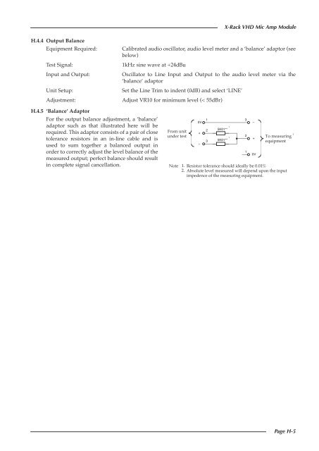
X-<strong>Rack</strong> <strong>VHD</strong> Mic Amp <strong>Module</strong>H.4.4 Output BalanceEquipment Required:Test Signal:<strong>Input</strong> and Output:Unit Setup:Adjustment:Calibrated audio oscillator, audio level meter and a ‘balance’ adaptor (seebelow)1kHz sine wave at +24dBuOscillator to Line <strong>Input</strong> and Output to the audio level meter via the‘balance’ adaptorSet the Line Trim to indent (0dB) and select ‘LINE’Adjust VR10 for minimum level (< 55dBr)H.4.5 ‘Balance’ AdaptorFor the output balance adjustment, a ‘balance’adaptor such as that illustrated here will berequired. This adaptor consists of a pair of closetolerance resistors in an in-line cable and isused to sum together a balanced output inorder to correctly adjust the level balance of themeasured output; perfect balance should resultin complete signal cancellation.From unitunder testNote0V+–12315K01**15K01**321–+0VTo measuringequipment1. Resistor tolerance should ideally be 0.01%2. Absolute level measured will depend upon the inputimpedence of the measuring equipment.2Page H-5