Analysis of 320X240 uncooled microbolometer focal plane array ...
Analysis of 320X240 uncooled microbolometer focal plane array ... Analysis of 320X240 uncooled microbolometer focal plane array ...
46of the resistors and the capacitor is chosen to match the input and output impedance of theTEC pump.Figure 4.9 Step response of the equivalent TEC pump model.was derived.Using the equivalent model, the transfer function, Hm(s), of the TEC pump model
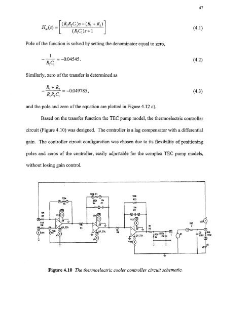
47[(RiR2C1)s + — (R1 + R2) 4.1( )(Rig)s +1Pole of the function is solved by setting the denominator equal to zero,1—0.04545.R1 Ci(4.2)Similarly, zero of the transfer is determined asR 1 + R 2- —0.049785,Ri R2 CI(4.3)and the pole and zero of the equation are plotted in Figure 4.12 c).Based on the transfer function the TEC pump model, the thermoelectric controllercircuit (Figure 4.10) was designed. The controller is a lag compensator with a differentialgain. The controller circuit configuration was chosen due to its flexibility of positioningpoles and zeros of the controller, easily adjustable for the complex TEC pump models,without losing gain control.Figure 4.10 The thermoelectric cooler controller circuit schematic.
- Page 8 and 9: This thesis is dedicated tomy famil
- Page 10 and 11: TABLE OF CONTENTSChapterPage1 INTRO
- Page 13 and 14: CHAPTER 1INTRODUCTIONIn recent year
- Page 17 and 18: 5radiation (LWIR) between 811m to 1
- Page 19 and 20: Figure 2.1 Simplified bolometer str
- Page 21 and 22: 9The first function of the right ha
- Page 23 and 24: 11corresponding to T 1 . With radia
- Page 25 and 26: 13then the transient term goes to z
- Page 27 and 28: 15The signal voltage (Eauation 2.26
- Page 29 and 30: 172.2.3 NoiseThe detection capabili
- Page 31 and 32: 19F is the f/# of the optics, VN is
- Page 33 and 34: 21To obtain the temperature fluctua
- Page 35 and 36: 23provide protection against detect
- Page 37 and 38: ZE1 L4t46LII C. 10 aft( IL.The UFPA
- Page 39 and 40: 27reflection (AR) coated Ge window
- Page 41 and 42: 29170 synchronization standard sign
- Page 43 and 44: 31amplified and integrated detector
- Page 45 and 46: 33processing module by a scan conve
- Page 47 and 48: Figure 3.3 UFPA camera platform.35
- Page 49 and 50: 37high mechanical strength as shown
- Page 51 and 52: Unlike the photon sensors, the micr
- Page 53 and 54: 414.2 The Controller DesignThe cont
- Page 55 and 56: 43performed at Inframetrics to dete
- Page 57: 45c) Heating of the TEC without hea
- Page 61 and 62: 49The third amplifier stage has the
- Page 63 and 64: t 1
- Page 65 and 66: 53c) T showing the response time of
- Page 67: REFERENCES1. R. A. Wood, "Uncooled
47[(RiR2C1)s + — (R1 + R2) 4.1( )(Rig)s +1Pole <strong>of</strong> the function is solved by setting the denominator equal to zero,1—0.04545.R1 Ci(4.2)Similarly, zero <strong>of</strong> the transfer is determined asR 1 + R 2- —0.049785,Ri R2 CI(4.3)and the pole and zero <strong>of</strong> the equation are plotted in Figure 4.12 c).Based on the transfer function the TEC pump model, the thermoelectric controllercircuit (Figure 4.10) was designed. The controller is a lag compensator with a differentialgain. The controller circuit configuration was chosen due to its flexibility <strong>of</strong> positioningpoles and zeros <strong>of</strong> the controller, easily adjustable for the complex TEC pump models,without losing gain control.Figure 4.10 The thermoelectric cooler controller circuit schematic.


