Analysis of 320X240 uncooled microbolometer focal plane array ...
Analysis of 320X240 uncooled microbolometer focal plane array ... Analysis of 320X240 uncooled microbolometer focal plane array ...
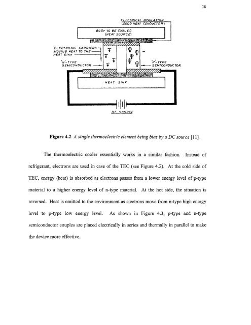
Figure 4.2 A single thermoelectric element being bias by a DC source [111The thermoelectric cooler essentially works in a similar fashion. Instead ofrefrigerant, electrons are used in case of the TEC (see Figure 4.2). At the cold side ofTEC, energy (heat) is absorbed as electrons passes from a lower energy level of p-typematerial to a higher energy level of n-type material. At the hot side, the situation isreversed. Heat is emitted to the environment as electrons move from n-type high energylevel to p-type low energy level. As shown in Figure 4.3, p-type and n-typesemiconductor couples are placed electrically in series and thermally in parallel to makethe device more effective.
Unlike the photon sensors, the microbolometer is a thermal sensor, and anychange in the environment that the microbolometer is in can affect the temperaturemeasurement. Therefore, the temperature inside the microbolometer packaging must bekept at a constant temperature. To accomplish this task, the thermoelectric cooler is usedto stabilize the temperature inside the FPA packaging. The operation of thermoelectriccooler is controlled by the amount and the direction of current. Positive current (puttingcurrent into TEC) will heat up one side of the thermoelectric cooler and cools the otherside of TEC, where the heat is removed from the cold side to the hot side. Negativecurrent (pulling current out of TEC) will reverse the direction of the heat flow. The rateof heat being pumped from the cold side to the hot side is proportional to the amount ofcurrent passing through the thermoelectric cooler and the number of couples [11]. In the
- Page 1 and 2: Copyright Warning & RestrictionsThe
- Page 3 and 4: ABSTRACTANALYSIS OF 320X240 UNCOOLE
- Page 6 and 7: APPROVAL PAGEANALYSIS OF 320X240 UN
- Page 8 and 9: This thesis is dedicated tomy famil
- Page 10 and 11: TABLE OF CONTENTSChapterPage1 INTRO
- Page 13 and 14: CHAPTER 1INTRODUCTIONIn recent year
- Page 17 and 18: 5radiation (LWIR) between 811m to 1
- Page 19 and 20: Figure 2.1 Simplified bolometer str
- Page 21 and 22: 9The first function of the right ha
- Page 23 and 24: 11corresponding to T 1 . With radia
- Page 25 and 26: 13then the transient term goes to z
- Page 27 and 28: 15The signal voltage (Eauation 2.26
- Page 29 and 30: 172.2.3 NoiseThe detection capabili
- Page 31 and 32: 19F is the f/# of the optics, VN is
- Page 33 and 34: 21To obtain the temperature fluctua
- Page 35 and 36: 23provide protection against detect
- Page 37 and 38: ZE1 L4t46LII C. 10 aft( IL.The UFPA
- Page 39 and 40: 27reflection (AR) coated Ge window
- Page 41 and 42: 29170 synchronization standard sign
- Page 43 and 44: 31amplified and integrated detector
- Page 45 and 46: 33processing module by a scan conve
- Page 47 and 48: Figure 3.3 UFPA camera platform.35
- Page 49: 37high mechanical strength as shown
- Page 53 and 54: 414.2 The Controller DesignThe cont
- Page 55 and 56: 43performed at Inframetrics to dete
- Page 57 and 58: 45c) Heating of the TEC without hea
- Page 59 and 60: 47[(RiR2C1)s + — (R1 + R2) 4.1( )
- Page 61 and 62: 49The third amplifier stage has the
- Page 63 and 64: t 1
- Page 65 and 66: 53c) T showing the response time of
- Page 67: REFERENCES1. R. A. Wood, "Uncooled
Figure 4.2 A single thermoelectric element being bias by a DC source [111The thermoelectric cooler essentially works in a similar fashion. Instead <strong>of</strong>refrigerant, electrons are used in case <strong>of</strong> the TEC (see Figure 4.2). At the cold side <strong>of</strong>TEC, energy (heat) is absorbed as electrons passes from a lower energy level <strong>of</strong> p-typematerial to a higher energy level <strong>of</strong> n-type material. At the hot side, the situation isreversed. Heat is emitted to the environment as electrons move from n-type high energylevel to p-type low energy level. As shown in Figure 4.3, p-type and n-typesemiconductor couples are placed electrically in series and thermally in parallel to makethe device more effective.


