Analysis of 320X240 uncooled microbolometer focal plane array ...
Analysis of 320X240 uncooled microbolometer focal plane array ... Analysis of 320X240 uncooled microbolometer focal plane array ...
CHAPTER 3CAMERA HARDWARE3.1 DesignFor the past several years, Inframetrics has been working to incorporate the uncooledtechnology into its product line. The initial work began with the development of thevideo head electronics to drive the Honeywell bipolar UFPA. Inframetrics developed theinterface board to filter, to sample and hold, and to digitize the bipolar array output. Toproduce a still frame imaging breadboard, the video head integrated the uncooled array,optics, interface board, and a commercially available frame grabber. Already existingFpaVIEW software, developed by Inframetrics, was expanded to interface the breadboardfor testing the Honeywell bipolar array.Recently, Inframetrics developed ThermaCAMTm imaging radiometer based onthe Hughes variable integration time PtSi array. The ThermaCAM Tm project goal is todevelop a platform for both cooled and uncooled detectors. ThermaCAM T" was designedto provide a standard electronics and software platform for a variety of array formats anddetector technologies, specifically the uncooled focal plane arrays. The camera hardwarecan be divided into two main functional blocks; the FPA interface module and the videoprocessing module.The FPA interface module provides all the biases, timing pulses, and output signalconditioning, electronically reconfigurable for a particular array being integrated with thesensor, necessary to operate the array. The module digitizes the array output and convertsthe array readout frame rate with the standard video output frame rate of the video32
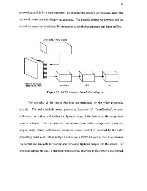
33processing module by a scan converter. To optimize the sensor's performance, array biasand clock levels are individually programmed. The specific timing requirement and thesize of the array can be adjusted by programming the timing generator and input buffers.Focal Plane Array AmpiirlersFigure 3.1 UFPA interface board block diagram.The majority of the sensor functions are performed by the video processingmodule. The tasks include image processing functions of "equalization", or nonuniformitycorrection, and scaling the dynamic range of the detector to the temperaturespan of interest. The user interface for measurement modes, temperature spans andranges, setup menus, colorization, zoom and cursor control is provided by the videoprocessing board also. Mass storage functions on a PCMCIA card as well as a commonfile format are available for storing and retrieving digitized images into the sensor. Forcommunications protocol, a standard remote control interface to the sensor is maintained.
- Page 1 and 2: Copyright Warning & RestrictionsThe
- Page 3 and 4: ABSTRACTANALYSIS OF 320X240 UNCOOLE
- Page 6 and 7: APPROVAL PAGEANALYSIS OF 320X240 UN
- Page 8 and 9: This thesis is dedicated tomy famil
- Page 10 and 11: TABLE OF CONTENTSChapterPage1 INTRO
- Page 13 and 14: CHAPTER 1INTRODUCTIONIn recent year
- Page 17 and 18: 5radiation (LWIR) between 811m to 1
- Page 19 and 20: Figure 2.1 Simplified bolometer str
- Page 21 and 22: 9The first function of the right ha
- Page 23 and 24: 11corresponding to T 1 . With radia
- Page 25 and 26: 13then the transient term goes to z
- Page 27 and 28: 15The signal voltage (Eauation 2.26
- Page 29 and 30: 172.2.3 NoiseThe detection capabili
- Page 31 and 32: 19F is the f/# of the optics, VN is
- Page 33 and 34: 21To obtain the temperature fluctua
- Page 35 and 36: 23provide protection against detect
- Page 37 and 38: ZE1 L4t46LII C. 10 aft( IL.The UFPA
- Page 39 and 40: 27reflection (AR) coated Ge window
- Page 41 and 42: 29170 synchronization standard sign
- Page 43: 31amplified and integrated detector
- Page 47 and 48: Figure 3.3 UFPA camera platform.35
- Page 49 and 50: 37high mechanical strength as shown
- Page 51 and 52: Unlike the photon sensors, the micr
- Page 53 and 54: 414.2 The Controller DesignThe cont
- Page 55 and 56: 43performed at Inframetrics to dete
- Page 57 and 58: 45c) Heating of the TEC without hea
- Page 59 and 60: 47[(RiR2C1)s + — (R1 + R2) 4.1( )
- Page 61 and 62: 49The third amplifier stage has the
- Page 63 and 64: t 1
- Page 65 and 66: 53c) T showing the response time of
- Page 67: REFERENCES1. R. A. Wood, "Uncooled
33processing module by a scan converter. To optimize the sensor's performance, <strong>array</strong> biasand clock levels are individually programmed. The specific timing requirement and thesize <strong>of</strong> the <strong>array</strong> can be adjusted by programming the timing generator and input buffers.Focal Plane Array AmpiirlersFigure 3.1 UFPA interface board block diagram.The majority <strong>of</strong> the sensor functions are performed by the video processingmodule. The tasks include image processing functions <strong>of</strong> "equalization", or nonuniformitycorrection, and scaling the dynamic range <strong>of</strong> the detector to the temperaturespan <strong>of</strong> interest. The user interface for measurement modes, temperature spans andranges, setup menus, colorization, zoom and cursor control is provided by the videoprocessing board also. Mass storage functions on a PCMCIA card as well as a commonfile format are available for storing and retrieving digitized images into the sensor. Forcommunications protocol, a standard remote control interface to the sensor is maintained.


