Analysis of 320X240 uncooled microbolometer focal plane array ...
Analysis of 320X240 uncooled microbolometer focal plane array ... Analysis of 320X240 uncooled microbolometer focal plane array ...
28Figure 2.14 Simplified fabrication steps for the microbridge structure [91An improved and simplified process for the microbridge structure is beingdeveloped by Rockwell. With the new process, the number of microbolometer arrayprocess steps can be reduced by 30%, and both metalization and dielectric processes areimproved. It eliminates two photomask layers and replaces wet-etch with dry-etchprocess. It is expected that UFPA performance will be improved with the 25% reductionin thermal conductance and a broadening of the spectral response band.2.4 TimingThe UFPA is design to output a single signal channel that is compatible with both U.Sand European (PAL) TV synchronization standards, where the image can be viewedwithout reformatting the output signal. The output video is TV (60 Hz) compatible RS-
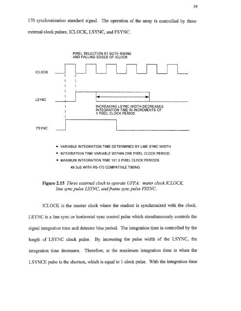
29170 synchronization standard signal. The operation of the array is controlled by threeexternal clock pulses; ICLOCK, LSYNC, and FSYNC.ICLOCK is the master clock where the readout is synchronized with the clock.LSYNC is a line sync or horizontal sync control pulse which simultaneously controls thesignal integration time and detector bias period. The integration time is controlled by thelength of LSYNC clock pulse. By increasing the pulse width of the LSYNC, theintegration time decreases. Therefore, at the maximum integration time is when theLSYNCE pulse is the shortest, which is equal to 1 clock pulse. With the integration time
- Page 1 and 2: Copyright Warning & RestrictionsThe
- Page 3 and 4: ABSTRACTANALYSIS OF 320X240 UNCOOLE
- Page 6 and 7: APPROVAL PAGEANALYSIS OF 320X240 UN
- Page 8 and 9: This thesis is dedicated tomy famil
- Page 10 and 11: TABLE OF CONTENTSChapterPage1 INTRO
- Page 13 and 14: CHAPTER 1INTRODUCTIONIn recent year
- Page 17 and 18: 5radiation (LWIR) between 811m to 1
- Page 19 and 20: Figure 2.1 Simplified bolometer str
- Page 21 and 22: 9The first function of the right ha
- Page 23 and 24: 11corresponding to T 1 . With radia
- Page 25 and 26: 13then the transient term goes to z
- Page 27 and 28: 15The signal voltage (Eauation 2.26
- Page 29 and 30: 172.2.3 NoiseThe detection capabili
- Page 31 and 32: 19F is the f/# of the optics, VN is
- Page 33 and 34: 21To obtain the temperature fluctua
- Page 35 and 36: 23provide protection against detect
- Page 37 and 38: ZE1 L4t46LII C. 10 aft( IL.The UFPA
- Page 39: 27reflection (AR) coated Ge window
- Page 43 and 44: 31amplified and integrated detector
- Page 45 and 46: 33processing module by a scan conve
- Page 47 and 48: Figure 3.3 UFPA camera platform.35
- Page 49 and 50: 37high mechanical strength as shown
- Page 51 and 52: Unlike the photon sensors, the micr
- Page 53 and 54: 414.2 The Controller DesignThe cont
- Page 55 and 56: 43performed at Inframetrics to dete
- Page 57 and 58: 45c) Heating of the TEC without hea
- Page 59 and 60: 47[(RiR2C1)s + — (R1 + R2) 4.1( )
- Page 61 and 62: 49The third amplifier stage has the
- Page 63 and 64: t 1
- Page 65 and 66: 53c) T showing the response time of
- Page 67: REFERENCES1. R. A. Wood, "Uncooled
29170 synchronization standard signal. The operation <strong>of</strong> the <strong>array</strong> is controlled by threeexternal clock pulses; ICLOCK, LSYNC, and FSYNC.ICLOCK is the master clock where the readout is synchronized with the clock.LSYNC is a line sync or horizontal sync control pulse which simultaneously controls thesignal integration time and detector bias period. The integration time is controlled by thelength <strong>of</strong> LSYNC clock pulse. By increasing the pulse width <strong>of</strong> the LSYNC, theintegration time decreases. Therefore, at the maximum integration time is when theLSYNCE pulse is the shortest, which is equal to 1 clock pulse. With the integration time


