Analysis of 320X240 uncooled microbolometer focal plane array ...
Analysis of 320X240 uncooled microbolometer focal plane array ... Analysis of 320X240 uncooled microbolometer focal plane array ...
18Noise equivalent temperature difference (NETD) is defined as the temperaturedifference seen in a large blackbody or between two adjacent large blackbodies by aninfrared thermal imaging system, which will give rise to signal to noise ratio of unity inthe electrical output of the focal plane array and readout electronics [9]. It is essentiallybolometer's sensitivity to temperature change.
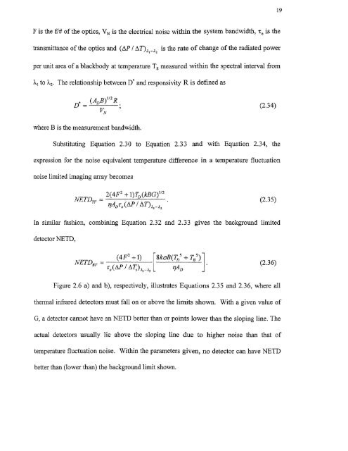
19F is the f/# of the optics, VN is the electrical noise within the system bandwidth, T o is thetransmittance of the optics and (AP / AT),I _ 12 is the rate of change of the radiated powerper unit area of a blackbody at temperature T s measured within the spectral interval from2 to k2. The relationship between D* and responsivity R is defined asD*(A DV B) 12 2 R (2.34)Nwhere B is the measurement bandwidth.Substituting Equation 2.30 to Equation 2.33 and with Equation 2.34, theexpression for the noise equivalent temperature difference in a temperature fluctuationFigure 2.6 a) and b), respectively, illustrates Equations 2.35 and 2.36, where allthermal infrared detectors must fall on or above the limits shown. With a given value ofG, a detector cannot have an NETD better than or points lower than the sloping line. Theactual detectors usually lie above the sloping line due to higher noise than that oftemperature fluctuation noise. Within the parameters given, no detector can have NETDbetter than (lower than) the background limit shown.
- Page 1 and 2: Copyright Warning & RestrictionsThe
- Page 3 and 4: ABSTRACTANALYSIS OF 320X240 UNCOOLE
- Page 6 and 7: APPROVAL PAGEANALYSIS OF 320X240 UN
- Page 8 and 9: This thesis is dedicated tomy famil
- Page 10 and 11: TABLE OF CONTENTSChapterPage1 INTRO
- Page 13 and 14: CHAPTER 1INTRODUCTIONIn recent year
- Page 17 and 18: 5radiation (LWIR) between 811m to 1
- Page 19 and 20: Figure 2.1 Simplified bolometer str
- Page 21 and 22: 9The first function of the right ha
- Page 23 and 24: 11corresponding to T 1 . With radia
- Page 25 and 26: 13then the transient term goes to z
- Page 27 and 28: 15The signal voltage (Eauation 2.26
- Page 29: 172.2.3 NoiseThe detection capabili
- Page 33 and 34: 21To obtain the temperature fluctua
- Page 35 and 36: 23provide protection against detect
- Page 37 and 38: ZE1 L4t46LII C. 10 aft( IL.The UFPA
- Page 39 and 40: 27reflection (AR) coated Ge window
- Page 41 and 42: 29170 synchronization standard sign
- Page 43 and 44: 31amplified and integrated detector
- Page 45 and 46: 33processing module by a scan conve
- Page 47 and 48: Figure 3.3 UFPA camera platform.35
- Page 49 and 50: 37high mechanical strength as shown
- Page 51 and 52: Unlike the photon sensors, the micr
- Page 53 and 54: 414.2 The Controller DesignThe cont
- Page 55 and 56: 43performed at Inframetrics to dete
- Page 57 and 58: 45c) Heating of the TEC without hea
- Page 59 and 60: 47[(RiR2C1)s + — (R1 + R2) 4.1( )
- Page 61 and 62: 49The third amplifier stage has the
- Page 63 and 64: t 1
- Page 65 and 66: 53c) T showing the response time of
- Page 67: REFERENCES1. R. A. Wood, "Uncooled
19F is the f/# <strong>of</strong> the optics, VN is the electrical noise within the system bandwidth, T o is thetransmittance <strong>of</strong> the optics and (AP / AT),I _ 12 is the rate <strong>of</strong> change <strong>of</strong> the radiated powerper unit area <strong>of</strong> a blackbody at temperature T s measured within the spectral interval from2 to k2. The relationship between D* and responsivity R is defined asD*(A DV B) 12 2 R (2.34)Nwhere B is the measurement bandwidth.Substituting Equation 2.30 to Equation 2.33 and with Equation 2.34, theexpression for the noise equivalent temperature difference in a temperature fluctuationFigure 2.6 a) and b), respectively, illustrates Equations 2.35 and 2.36, where allthermal infrared detectors must fall on or above the limits shown. With a given value <strong>of</strong>G, a detector cannot have an NETD better than or points lower than the sloping line. Theactual detectors usually lie above the sloping line due to higher noise than that <strong>of</strong>temperature fluctuation noise. Within the parameters given, no detector can have NETDbetter than (lower than) the background limit shown.


