Analysis of 320X240 uncooled microbolometer focal plane array ...
Analysis of 320X240 uncooled microbolometer focal plane array ... Analysis of 320X240 uncooled microbolometer focal plane array ...
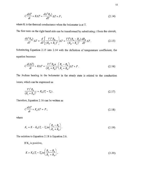
12dAT d(i2R )C + KAT — dTB AT + P ;dt(2.14)Substituting Equation 2.15 into 2.14 with the definition of temperature coefficient, theequation becomesd(AT) + KATV1 2 Rya (RL — RBdt + RB ) 2 RB+ P(2.16)The Joulean heating in the bolometer in the steady state is related to the conductionlosses, which can be expressed as
13then the transient term goes to zero with time and the periodic function is left. However,ifthen the transient term increases exponentially large until eventually the bolometeroverheats and bums up. Assuming that R I, is much greater than RB and thermalconductance stays about the same with change in temperature (1( ,K0), the unstable bumout condition is whena (7; — To ) > 1. (2.22)For metals, where a decreases with temperature (Equation 2.10), it does not meet thecondition in Equation 2.22, and self-burnout does not occur. However, in the case ofthermistor material, if the bias current is large enough, it will overheat and burnout. Theself burnout condition is given byThe value of )611;2 is about 0.04 for thermistor materials. If the bolometer is at anambient temperature of 300K, then the critical temperature for self-burnout is about325K [7].2.2.2 ResponsivityFrom the definition of temperature coefficient (Equation 2.8), the change in the bolometerresistance due to change in temperature by AT is
- Page 1 and 2: Copyright Warning & RestrictionsThe
- Page 3 and 4: ABSTRACTANALYSIS OF 320X240 UNCOOLE
- Page 6 and 7: APPROVAL PAGEANALYSIS OF 320X240 UN
- Page 8 and 9: This thesis is dedicated tomy famil
- Page 10 and 11: TABLE OF CONTENTSChapterPage1 INTRO
- Page 13 and 14: CHAPTER 1INTRODUCTIONIn recent year
- Page 17 and 18: 5radiation (LWIR) between 811m to 1
- Page 19 and 20: Figure 2.1 Simplified bolometer str
- Page 21 and 22: 9The first function of the right ha
- Page 23: 11corresponding to T 1 . With radia
- Page 27 and 28: 15The signal voltage (Eauation 2.26
- Page 29 and 30: 172.2.3 NoiseThe detection capabili
- Page 31 and 32: 19F is the f/# of the optics, VN is
- Page 33 and 34: 21To obtain the temperature fluctua
- Page 35 and 36: 23provide protection against detect
- Page 37 and 38: ZE1 L4t46LII C. 10 aft( IL.The UFPA
- Page 39 and 40: 27reflection (AR) coated Ge window
- Page 41 and 42: 29170 synchronization standard sign
- Page 43 and 44: 31amplified and integrated detector
- Page 45 and 46: 33processing module by a scan conve
- Page 47 and 48: Figure 3.3 UFPA camera platform.35
- Page 49 and 50: 37high mechanical strength as shown
- Page 51 and 52: Unlike the photon sensors, the micr
- Page 53 and 54: 414.2 The Controller DesignThe cont
- Page 55 and 56: 43performed at Inframetrics to dete
- Page 57 and 58: 45c) Heating of the TEC without hea
- Page 59 and 60: 47[(RiR2C1)s + — (R1 + R2) 4.1( )
- Page 61 and 62: 49The third amplifier stage has the
- Page 63 and 64: t 1
- Page 65 and 66: 53c) T showing the response time of
- Page 67: REFERENCES1. R. A. Wood, "Uncooled
12dAT d(i2R )C + KAT — dTB AT + P ;dt(2.14)Substituting Equation 2.15 into 2.14 with the definition <strong>of</strong> temperature coefficient, theequation becomesd(AT) + KATV1 2 Rya (RL — RBdt + RB ) 2 RB+ P(2.16)The Joulean heating in the bolometer in the steady state is related to the conductionlosses, which can be expressed as


