Download A PDF Of These Pages (505 KB) - ShopNotes
Download A PDF Of These Pages (505 KB) - ShopNotes
Download A PDF Of These Pages (505 KB) - ShopNotes

You also want an ePaper? Increase the reach of your titles
YUMPU automatically turns print PDFs into web optimized ePapers that Google loves.
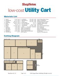
outfitting theVisesVises can make or break a workbench.But you don’t need to worryabout that with this workbench.The vises you see here are rocksolidand will handle the mostdemanding tasks with ease.COMPLETING THE TAIL VISEAt first glance, the tail vise at rightlooks like a solid block of wood.But what’s interesting is what youdon’t see. And that’s the metalhardware on the “inside.”In Figures 13 and 14, you cansee that the key pieces of hardwareare the mounting plate attached tothe front apron and the two guideplates that sandwich it. As youturn the handle, these plates guidethe assembly smoothly as ittravels back and forth.For the most part, the rest of theparts of the vise assembly keep theplates spaced correctly. The secretto adding them is to trial fit everythingas you go along. So you’llTAIL VISEneed to disassemble and thenreassemble the tail vise a few times.Mounting the Plate. The firstthing you’ll need to do is attach thetail vise mounting plate (Figure 13).This plate fits into the recess in thefront apron and is screwed in placeso the top edge extends just abovethe bottom edge of the aprongroove, as in the End View at left.Once the plate is in place, the nextstep is to size the tail vise top andattach the metal guide plate of thetail vise. What you’re looking forhere is to end up with the tail visetop flush with the top of the benchwhen the guide plate is hooked over13 OVERVIEW a.14the mounting plate (Figure 13a).And there shouldn’t be any gapbetween the apron on the bench andthe edge of the tail vise top.To help locate everything accurately,I clamped the two piecestogether and test fit it to the bench.Once you have the tail vise topsized and the guide plate located,you can screw them together.Note: You’ll also need to drill acouple counterbores in the tail visetop for the ends of the bolts used toclamp the lower guide plate inplace, as in Figure 14. You can usethe guide plate to locate them.At this point, the critical“assembly” of the vise is over. Allthat’s left to do now is add the twofiller blocks and the tail visebottom. Here again, test fitting willhelp you size the blocks and bottompiece for a smooth sliding fit.Add the Bench Dog Strip. Nowyou’re ready to add the tail visestrip that holds the bench dogs. Asbefore, page 15 covers everything40 www.<strong>ShopNotes</strong>.com
a.you need to know. Once the dogholes are complete, glue the strip tothe tail vise assembly.To complete the tail vise, I addeda “pinch” block to the inside face ofthe vise. This gives the mountingcollar and handle for the vise a“centered” look and covers the endof the vise hardware (Figure 13).Finally, add the handle to the vise.You can make your own or buy one(see sources on page 51).15FIGUREADDING THE FACE VISEAll that’s left to complete the benchis to add a face vise. The nice thingis, there are only two parts to make— a face vise block and a collar supportstrip, as shown in Figure 15.Like the tail vise, you’ll need todisassemble and reassemble thevise a few times. Plus, drillingslightly oversized holes (detailed inthe drawings) helps avoid anyalignment problems.Mounting the Vise. The first stepis to disassemble the vise and boltthe mounting plate to the bottom ofthe bench (Figures 15a and 15b).The next step is to make the supportblock for the metal collars thatprovide extra support for the guiderods (Figure 15). Note: You’ll needto cut a couple notches where thestrip covers the bench dog holes.After drilling a pair of oversizedholes in the collar support block forthe guide rods and screw, bolt theblock to the bench, as in Figure 15.Now, slide the support collarsonto the shafts and assemble thevise by feeding the rods throughthe collar support block, into thevise mounting plate.The next step is to slide the supportcollars up to the support blockand trace around the outsideedges. Now, disassemble the vise(again) and using the tracing as aguide, drill a counterbore for thesupport collars. Note: The counterborecan be slightly oversized withthe supports collars flush with theface of the support block.With that complete, bolt the supportstrip back in place andreassemble the vise. Then, slide thecollars into the counterbores andscrew them in place.All that’s left to do now is makethe face vise block (Figure 15). Aftergluing up the block and roundingthe edges, drill a set of holes for theguide rods and threaded shaft.<strong>These</strong> holes should align with theholes in the support block. And besure to locate the holes so the blockends up flush with the left end andtop edge of the bench.After slipping the face vise blockover the rods and shaft, tighten thevise to “clamp” the block to thebench. Then simply screw theblock in place, as shown in Figure15b. Then all that’s left to do is adda handle to the vise and startworking at your new bench.b.FACE VISEwww.<strong>ShopNotes</strong>.com 41